EP0891294B1 - Procede et dispositif de stockage et de degagement d'hydrogene - Google Patents
Procede et dispositif de stockage et de degagement d'hydrogene Download PDFInfo
- Publication number
- EP0891294B1 EP0891294B1 EP97919962A EP97919962A EP0891294B1 EP 0891294 B1 EP0891294 B1 EP 0891294B1 EP 97919962 A EP97919962 A EP 97919962A EP 97919962 A EP97919962 A EP 97919962A EP 0891294 B1 EP0891294 B1 EP 0891294B1
- Authority
- EP
- European Patent Office
- Prior art keywords
- hydrogen
- container
- storage medium
- storage device
- hydrogen storage
- Prior art date
- Legal status (The legal status is an assumption and is not a legal conclusion. Google has not performed a legal analysis and makes no representation as to the accuracy of the status listed.)
- Expired - Lifetime
Links
Images


Classifications
-
- F—MECHANICAL ENGINEERING; LIGHTING; HEATING; WEAPONS; BLASTING
- F17—STORING OR DISTRIBUTING GASES OR LIQUIDS
- F17C—VESSELS FOR CONTAINING OR STORING COMPRESSED, LIQUEFIED OR SOLIDIFIED GASES; FIXED-CAPACITY GAS-HOLDERS; FILLING VESSELS WITH, OR DISCHARGING FROM VESSELS, COMPRESSED, LIQUEFIED, OR SOLIDIFIED GASES
- F17C11/00—Use of gas-solvents or gas-sorbents in vessels
- F17C11/005—Use of gas-solvents or gas-sorbents in vessels for hydrogen
-
- C—CHEMISTRY; METALLURGY
- C01—INORGANIC CHEMISTRY
- C01B—NON-METALLIC ELEMENTS; COMPOUNDS THEREOF; METALLOIDS OR COMPOUNDS THEREOF NOT COVERED BY SUBCLASS C01C
- C01B3/00—Hydrogen; Gaseous mixtures containing hydrogen; Separation of hydrogen from mixtures containing it; Purification of hydrogen; Reversible storage of hydrogen
- C01B3/0005—Reversible storage of hydrogen, e.g. by hydrogen getters or electrodes
-
- Y—GENERAL TAGGING OF NEW TECHNOLOGICAL DEVELOPMENTS; GENERAL TAGGING OF CROSS-SECTIONAL TECHNOLOGIES SPANNING OVER SEVERAL SECTIONS OF THE IPC; TECHNICAL SUBJECTS COVERED BY FORMER USPC CROSS-REFERENCE ART COLLECTIONS [XRACs] AND DIGESTS
- Y02—TECHNOLOGIES OR APPLICATIONS FOR MITIGATION OR ADAPTATION AGAINST CLIMATE CHANGE
- Y02E—REDUCTION OF GREENHOUSE GAS [GHG] EMISSIONS, RELATED TO ENERGY GENERATION, TRANSMISSION OR DISTRIBUTION
- Y02E60/00—Enabling technologies; Technologies with a potential or indirect contribution to GHG emissions mitigation
- Y02E60/30—Hydrogen technology
- Y02E60/32—Hydrogen storage
Definitions
- This invention relates to a rechargeable device for storing and, when desired, releasing hydrogen.
- the device can be used in the energy generation or transportation industries.
- Hydrogen burns cleanly in air, producing water as a "waste" product.
- Powering vehicles, machinery or appliances with hydrogen powered engines or fuel cells eliminates the air pollution associated with fossil fuel powered engines.
- the heat value per volume of hydrogen is very low compared to fossil fuels like gasoline.
- the heat value per volume can be increased by placing the hydrogen under several MPa (thousands of pounds per square inch) of pressure, cooling it to a liquid, or absorbing it into a solid such as a metal hydride.
- Pressurising or liquefying hydrogen requires bulky, expensive processing and storage equipment. It can also be dangerous. For instance, if liquid hydrogen is heated, it converts to a gas. This may significantly raise the pressure within its storage device, with possible drastic consequences.
- Metal hydrides are heavy, however.
- the gravitational density of hydrogen is very low. This means the amount of energy per weight of metal hydride may be low compared to fossil fuels.
- Metal hydride also creates several engineering problems. For instance, metal hydride tends to break down into fine particles that can plug a gas filter. The hydride particles expand and contract upon hydrogen absorption and desorption, respectively. This may cause densely packed metal hydride beds to form that when they expand may damage the container holding the metal hydride. Adding or removing heat is necessary to the hydrogen absorption and desorption processes; hydride powders transfer heat poorly, however.
- Japanese publication no.63035401 discloses a container containing hydrogen-occlusion alloy in a number of cells of a a honeycomb structure included in a cylinder.
- the axes of the cells are parallel to the axis of the container.
- a plurality of partition plates parallel to the cross-section of the container are placed inside the container to reinforce the container.
- US patent no. 4505120 to Golben discloses a cylinder filled with an aluminium foam matrix which contains a solid hydrogen-absorbing alloy.
- the Golben container approaches the poor heat transfer property of hydride powders and the hydride expansion problem by containing the hydride powder in the aluminium foam and uses an axial spring filter to absorb the expansion forces generated by the hydride particles.
- US patent no. 4609038 to Ishikawa et al. discloses a heat exchanger using a hydrogen occlusion alloy formed into a compact with a dissimilar metal. This is stated to avoid “micronization” of the alloy.
- a solid storage medium like metal hydride in a ground particle form, may be used to hold hydrogen.
- the storage medium is placed within a container.
- Dividers partition the container into chambers.
- a matrix formed from a thermal foam or other appropriate materials and placed within the container, improves heat transfer and holds the solid hydrogen storage medium in separate cells.
- the storage medium may migrate somewhat among cells, the dividers prevent the storage medium from migrating into a different chamber. This helps evenly distribute the storage medium.
- metal hydride particles are selected as the storage medium, the cell format avoids excessive particle settling but allows for particle expansion and contraction.
- the device also provides a modular design so that the total hydrogen capacity is flexible.
- the matrix thermally couples to a heat transferring surface.
- a channel or conduit can be provided for conveying a fluid by which heat is removed or added to the container to cause hydrogen absorption or desorption from the storage medium.
- the matrix is thermally conductive, it fully distributes heat throughout the container or transfers it to the heat transferring surface for removal by a coolant fluid.
- a heat transferring surface also could be formed by a heated, electrically or otherwise, platen placed in contact with the outer container walls, to the inside of which the matrix may be tightly fitted for good thermal conductivity. When heat removal is necessary, the platen could be cooled by surface radiation, assisted by a fan and/or thermal fins located on the platen side not coupled to the outer container walls.
- a port located in the container allows hydrogen to enter in order to recharge the storage medium or exit when hydrogen desorption occurs.
- a porous filter positioned within the port, keeps the storage medium in the container, while allowing hydrogen to pass. If the filter extends throughout most of the container it also helps hydrogen fluid circulate to and from the chambers.
- the hydrogen storage device comprises one or more modules.
- a module may be composed of multiple interconnected containers, each formed from two roughly concentric pipes that lay horizontally. Attached or fitted tightly to the outside of the inner pipe is the matrix formed from a thermal foam, like an aluminium foam. It substantially fills the space between the two pipes.
- the thermal foam matrix forms a network of open cells. Metal hydride particles (or another hydrogen storing solid) occupy and migrate among these cells. But the particles cannot pass between dividers that partition the container into chambers providing even distribution while ensuring sufficient space for particle expansion following hydrogen absorption. This may be done by ensuring that the ratio of chamber length to container (inner) diameter ranges between about 0.5 and 2, and preferably is about 1.
- Each module has several such containers, whose inner pipes and ports are interconnected.
- a hot fluid may be circulated through the inner pipes to release the hydrogen.
- Thermal foam matrixes are tightly coupled to the outside of the inner pipes; each therefore distributes heat through its cells and ultimately to the storage medium.
- hydrogen is pumped into the interconnected ports, flows through the open cells and circulates about the storage medium. Hydrogen absorption results; it generates heat, which the thermal foam matrixes conduct to the inner pipes.
- a coolant fluid conveyed through the interconnected inner pipes removes the heat, thus increasing the efficiency of the charging process.
- Storage containers can be formed in virtually any shape.
- rectangular ducts partitioned into chambers having multiple cells could be used to hold the metal hydride particles.
- a channel for circulating coolant or hot fluids could surround the duct, pass through it or lie adjacent one or more of its walls to create a surface for adding or removing heat.
- a thermal foam matrix is thermally coupled to the surface for distributing the added heat throughout the container or delivering heat generated in the container to the surface, for removal.
- a generally "U-shaped" conduit inserts into the container for circulating heat transferring fluid that enters through one opening in the conduit and exits from another.
- the U-shaped conduit is particularly appropriate for a storage device whose length is more than about five times its (inner) diameter.
- a straight length of conduit or inner pipe may expand or contract with temperature changes; these movements may stress the container or the seals at the intersection of conduit and container.
- the U-shaped conduit particularly if its base is separated a slight distance from the container end wall, allows for such expansion and contraction.
- fluid enters the lower leg of the conduit that is positioned near the container bottom. This cools the lower part of the container first during hydrogen absorption.
- the solid storage medium absorbs hydrogen, it will be able to push the top layers up as it expands. Failure to first cool the lower end may slow absorption and stress the container.
- Multiple containers in these or other configurations, can be interconnected into modules; multiple modules can be interconnected to even further increase the total hydrogen storage capacity of the device.
- two fluid-circulating conduits for different containers could be coupled so that the same coolant or hot fluid (e.g., water or air) circulates through both.
- their ports can be manifolded together to allow for charging or discharging.
- several such modules could be interconnected to even further increase storage capacity or facilitate hydrogen release or charging of the selected solid hydrogen storage medium.
- Ground metal hydride particles may be selected as the solid hydrogen storage medium.
- a reasonably priced metal hydride alloy can hold about 1.3% hydrogen by weight. But other materials could also be used.
- the percentage weight of hydrogen that can be stored in solid form is expected to increase as present materials are refined or new ones developed. Or the cost of better, presently available but expensive hydrogen storing solids may decline. Those new, better or cheaper storage mediums also can be used with the present invention.
- This hydrogen storage device can be used in the energy and transportation industries. For instance, it can be used as a "hydrogen tank” for buses, cars, trucks, locomotives, boats or other vehicles presently using internal combustion engines or fuel cells. Additionally, such "hydrogen tanks” can be used for mobile power sources presently provided by gasoline or diesel fuel generators.
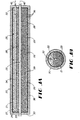
- Figure 1A shows a side view of one embodiment of a hydrogen storage device according to the present invention.
- Figure 1B shows a cross-sectional view of the embodiment shown in Figure 1A.
- Figure 2A shows a top view of an alternate embodiment of a hydrogen storage device comprising four interconnected containers.
- Figure 2B shows a cross-sectional view of the alternate embodiment shown in Figure 2A.
- Figure 3A shows a side view of yet another alternate embodiment of a hydrogen storage container.
- Figure 3B shows a cross-sectional view of the alternate embodiment shown in Figure 3A.
- Figure 1 shows one embodiment of the invention that has a container 20.
- a conduit 22 passes through container 20.
- Dividers 28 partition container 20 into chambers 29.
- Between the conduit 22 and an outer container wall 21 lies a matrix 26 that forms numerous open cells 27.
- Insulation 38 may surround the container 20. Such insulation 38 helps prevent heat transfer from or to the ambient environment that may affect hydrogen absorption or desorption.
- a port 32 pierces both the insulation 38 and container wall 21 and allows a hydrogen fluid 42 to transfer to and from the container 20.
- a fluid 40 may flow through the conduit 22.
- Fluid 40 may be heated water at, for instance, a temperature of 80°C.
- Fluid 40 could also be air or another liquid or gas suitable for transferring heat to and from the container 20.
- Heat carried by the fluid 40 is transferred through conduit walls 23 of the conduit 22.
- Conduit walls 23 thus both provide a surface through which heat is conveyed to and from the container 20 and also form interior walls for container 20.
- Matrix 26 preferably thermally couples (i.e., attaches snugly to the walls 23) to the conduit 22. Heat conducted through the conduit walls 23 may be distributed by the matrix 26 throughout the cells 27 to assist hydrogen desorption from a solid hydrogen storage medium held in the cells 27.
- One solid storage medium may be a metal hydride, preferably in a particle form.
- metal hydride preferably in a particle form.
- Mischmetal is an alloy that consists of a crude mixture of Cerium, Lanthanum, Neodymium and other rare-earth metals in the approximate ratio in which they naturally occur in the ore. Separating the Lanthanum entirely from the mixture is expensive, so the mixture itself is used to make the metal hydride alloy.) Although the Lm-Ni-Al alloy does not have the highest available percent weight concentration, it costs less than solids that could store more hydrogen by weight. If the percent by weight storage capacity of a particular solid storage medium is better (preferably 3% or more by weight), the same design could be used and the hydrogen storage capacity could be roughly tripled; or, the hydrogen storage capacity could be kept constant but the weight of the storage device could be decreased by a third or so.
- the present invention can be used with any solid storage medium. Indeed, it is anticipated that solids that can store more hydrogen by weight and still be reasonably priced will become available. This is important because as the weight of a fully charged hydrogen storage device decreases, the device becomes more feasible for commercial use in the transportation industry since the amount of energy delivered per unit of weight increases.
- properly heated fluid 40 flowing through the conduit 22 causes or assists hydrogen desorption as heat transfers through the conduit walls 23, conducts through matrix 26 to various cells 27 and, ultimately, transfers to the solid storage medium, causing it to desorb hydrogen.
- Hydrogen gas flows through open cells 27 and ultimately from the container 20 via the port 32.
- Port 32 may be outfitted with a porous filter 34 that passes hydrogen fluid but prevents passage of metal hydride particles through the port 32. Filter 34 may be formed of metal or another appropriate material.
- port 32 can also accept incoming hydrogen that is reabsorbed by the solid storage medium. Circulating a coolant fluid 40 through conduit 22 will draw out the resulting generated heat, speeding and improving the hydrogen absorption process.
- Figure 1 also shows a cross-sectional view of the container 20, conduit 22, conduit walls 23 through which heat flows, outer container walls 21 and port 32.
- Matrix 26 fills the generally annular space separating the conduit 22 and outer walls 21 of the container 20 with multiple cells 27.
- An alternative embodiment could be formed by placing matrix 26 that forms the cells 27 within the conduit 22, sealing its ends but for the port 32, which would then be on conduit 22, and circulating heat transferring fluid through the annular space between conduit 22 and the outer container walls 21.
- Figure 2 shows four containers 20 interconnected to form a module 10 that is a larger capacity hydrogen storage device.
- the ports 32 1,2,3,4 are connected by a hydrogen manifold 50.
- a fluid manifold 52 connects the hollow cores 22 1,2,3,4 through which fluid 40 flows.
- Other means like tubing or pipes, could be used to couple the containers 20. Circulating a hot fluid 40 through the fluid manifold 52 transfers heat to each container 20, whose outer walls 21 can be thermally coupled for encouraging heat transfer among the containers 20.
- This causes hydrogen fluid 42 to discharge and flow out of ports 32 1,2,3,4 and into the hydrogen manifold 50. Again, the process can be reversed for recharging the hydrogen solid storage medium held within the cells 27.
- hydrogen fluid 42 is pumped through hydrogen manifold 50, flows through the ports 32 1,2,3,4 into the containers 20, circulates among chambers 29 and is absorbed by the storage medium in the cells 27.
- the heat generated following absorption is conducted by matrix 26 to the conduit walls 23, which then transfer the heat to a coolant fluid 40 conveyed by the fluid manifold 52 into conduits 22.
- containers 20 could be coupled together to form modules 10, or many multiple modules 10 could be interconnected in order to form a higher capacity hydrogen storage device. These interconnections could also be temporary. This would allow for more efficient charging as multiple containers 20 or modules 10 could be interconnected and charged together, then separated and dispersed back to various vehicles or power generation sites.
- the ability of the storage medium to be recharged degrades after multiple rechargings because impurities within the hydrogen gas used for recharging will impede the ability of the storage medium to store hydrogen.
- the recharging hydrogen fluid has oxygen impurities and the storage medium is a metal hydride, some metal hydride particles will oxidise. That oxidised material will not be able to reabsorb hydrogen; over time, the hydrogen storage capacity of the storage device gradually decreases.
- the container 20 can be made recyclable.
- Means for refuelling the container 20 may be provided.
- fuelling ports can be located within each chamber 29. Periodically, fuelling ports could be opened, old storage medium removed and new storage medium provided through the fuelling ports. Removable plugs for the fuelling ports maintain container 20 integrity. Fuelling ports also can be used to charge the container 20 if it is first fabricated with everything but the hydrogen storage medium.
- FIG. 3 shows an alternative embodiment of a hydrogen storage device container 20.
- Outer container wall 21 surrounds various sections of thermal foam matrix 26 separated by dividers 28. When placed in the container 20, matrix 26 forms the cells 27.
- Metal hydride particles 36 occupy most but not all of the cells 27 in the matrix 26.
- Insulation 38 surrounds the outer container wall 21 except for where a U-shaped conduit 22 and the hydrogen port 32 pierce the container wall 21.
- U-shaped conduit 22 exposes more heat conducting surface area to the chambers 29 within the container 20 than does a straight conduit 22. This allows for better heat transfer from the fluid 40 flowing through the U-shaped conduit 22.
- fluid 40 can either be a coolant for removing heat from the container 20 during the charging process or fluid 40 can be heated in order to transfer heat to the container 20 and cause hydrogen desorption.
- Desorbed hydrogen flows through the porous filter 34 that extends substantially throughout the container 20. Extending the filter 34 through most of the container 20, or at least partially into each chamber 29, improves hydrogen fluid 42 flow within the container 20, allowing for better hydrogen desorption and absorption. But the filter 34 could be much shorter and dividers 28 could just be made permeable to hydrogen fluid 42 flow. Additionally making the dividers 28 non-permeable to metal hydride particles 36 prevents their migration among different chambers 29 within the container 20, thereby keeping an even distribution of the metal hydride particles 36 among the chambers in the container 20.
- U-shaped conduit 22 is particularly useful for a container 20 whose ratio of container length to container diameter is greater than about five. For such longer containers, a straight conduit 22 will expand and contract in its centre portion as temperature changes. This expansion and contraction stresses the seals about the ends 30 of the container 20 through which straight conduit 22 passes. Ultimately, the seals on the container 20 ends 30 may break, weaken or leak. U-shaped conduit 22 avoids this problem because its U-shaped end freely expands and contracts as it is positioned a slight distance away from the container end 30.
- a lower leg 24 of the U-shaped conduit 22 is located close to the bottom of the container 20. Fluid flows into this lower leg 24 and out of the upper leg 25.
- the heat will rise naturally through the container 20 and thereby be more evenly distributed.
- One specific embodiment of the hydrogen storage device container 20 shown in Figure 3 may be formed from a roughly five foot long stainless steel outer tube, with a three and one-half inch outer diameter and having sixty five mil (0.065 inch) thick walls, which when sealed at its open ends forms the container 20.
- a 3 ⁇ 4 inch, schedule ten, stainless steel U-shaped conduit 22 may be provided for conveying fluid 40.
- Filter 34 inserted and sealed into the port 32 may be a sintered porous stainless steel tube about 1 ⁇ 2 inch in diameter, about four feet ten inches long and provided with multiple pores about ten microns ( ⁇ m) in size.
- Matrix 26 is attached snugly to the outer surface of the conduit 22 to ensure good contact between the matrix and the conduit 22, soldering or welding may be used.
- Matrix 26 can be formed in several segments or one lengthy segment; to fill one chamber 29 at a time. If matrix 26 is formed from an aluminium thermal foam material, cells 27 in the matrix 26 will be about 0.05 to 0.1 inches in diameter.
- aluminium thermal foam is commercially available from: Energy Research and Generation, Inc., with an office at 900 Stanford Avenue, Oakland, California, and which sells its aluminium foam product under the "DUOCELLTM" name.
- Matrix 26 could also, however, be formed from other thermal foam or even more rigid materials, although preferably thermally conductive ones.
- Cells 27 may be partially filled with metal hydride particles to an average density of about forty percent (40%) of the theoretical metal density of the metal hydride. Because the metal hydride is in particle form, its actual bulk takes up more volume than predicted by the theoretical metal density of the metal hydride. Moreover, when the metal hydride particles are saturated with hydrogen, they expand about twenty to thirty percent (20-30%). Accordingly, cells 27 should be filled with metal hydride particles 36 in an amount significantly less than their theoretical density and at least somewhat less than their bulk density. For this particular embodiment, the forty percent (40%) threshold was chosen based on working experience with metal hydride materials. Other materials that may have different expansion properties may result in a different filling percentage.
- Assembly of this specific embodiment of the hydrogen storage device container 20 may be made by first placing the outer tube in a vertical position. U-shaped conduit 22 and the filter 34 are positioned over the outer tube.
- the holes in the foam section may be slightly smaller than the outside diameter of the conduit; this ensures a tight fit and thermal coupling between foam section and the conduit 22.
- the foam section is slid down the conduit 22 until it nests against the first divider 28 (or the sealed end 30 of the container 20). Some space separates the end of the conduit 22 from the end 30 of the container 20.
- Metal hydride powder may then be placed within this first foam section.
- a second disc-shaped divider 28 is then slid down the conduit 22 until it nests against the first foam section.
- the distance between the first and second dividers 28 should be such that the chamber length divided by the container diameter generates a ratio between about 0.5 to 2 and preferably 1.
- Chamber length is important because when particles expand during hydrogen absorption, they must expand up and out into the cells 27. But if dividers 28 make the chambers 29 too narrow, the solid storage medium expands only with difficulty. On the other hand, if chambers 29 are too long, and the container 20 shifts, solid storage medium can migrate within a chamber 29 to concentrate on one end. When the solid storage medium at that full end of the chamber 29 expands, it may form a tightly packed "cake" that places stress on the container 20. A one-to-one ratio between chamber 29 length and container 20 diameter is preferred as it helps prevent cake formation while also allowing for particle expansion.
- a portion of the conduit 22, the first divider 28, the first foam section, and the second divider 28 are then slid into the outer tube.
- a second foam section is slid down the conduit 22 until it nests against the second divider 28.
- Metal hydride particles 36 are inserted, another divider 28 is placed over the second foam section and the process repeats until the container 20 is filled with dividers 28, foam matrix 26 sections and metal hydride particles 36.
- Removable or permanently sealed caps can be placed on the outer tube to seal the container 20, but for a hydrogen port 32 and the lower and upper legs 24, 25 of conduit 22.
- matrix 26 could be preformed into sections, provided with a backing and attached or fitted to a shell that could then be attached to the conduit 22. Attachment could be interlocking tabs, by welding or soldering. Or, dividers 28 and foam matrix 26 sections could be separately soldered or welded to conduit 22.
- the container 20 (which is 1.5 meters (five feet) long and has a 8.75 cm (three and one-half inch) outer diameter with a 165 ⁇ m (sixty-five mil) thick wall) is filled with twenty-four kilograms of the Lm-Ni-Al alloy that has a hydrogen capacity of about 310 grams (3,500 standard litres).
- a hydrogen discharge pressure of about ten atmospheres is created.
- Integrity of the container 20 is important, particularly for its outer shell.
- the container 20 must be formed of a material and design that will withstand whatever hydrogen discharge pressures are selected for a particular storage device. For example, a 165 ⁇ m (sixty-five mil) stainless steel outer tube could be chosen to withstand a 3.45MPa (500 psi) discharge pressure.
Landscapes
- Chemical & Material Sciences (AREA)
- Engineering & Computer Science (AREA)
- Organic Chemistry (AREA)
- Chemical Kinetics & Catalysis (AREA)
- Combustion & Propulsion (AREA)
- Inorganic Chemistry (AREA)
- Mechanical Engineering (AREA)
- General Engineering & Computer Science (AREA)
- Filling Or Discharging Of Gas Storage Vessels (AREA)
- Hydrogen, Water And Hydrids (AREA)
- Treatments For Attaching Organic Compounds To Fibrous Goods (AREA)
- Solid-Sorbent Or Filter-Aiding Compositions (AREA)
Claims (11)
- Dispositif rechargeable pour le stockage d'hydrogène, comprenant:et caractérisé en outre par le fait que le milieu pour le stockage d'hydrogène remplit partiellement certaines, mais pas la totalité, des alvéoles (27) de la matrice, la structure à alvéoles ouvertes de la matrice permettant la migration du milieu pour le stockage d'hydrogène entre les alvéoles d'une chambre donnée.a) un récipient (20)b) une matrice conductrice thermique (26), à alvéoles ouvertes, disposée dans les chambres et retenant un milieu pour le stockage d'hydrogène
caractérisé par le fait qu'il comprend:c) une pluralité d'éléments diviseurs (28) compartimentant le récipient (20) en chambres (29), - Dispositif rechargeable pour le stockage d'hydrogène selon la revendication 1, comprenant en outre un orifice (32) à travers lequel de l'hydrogène peut s'écouler, et des moyens associés à l'orifice pour retenir le milieu de stockage dans le récipient.
- Dispositif rechargeable pour le stockage d'hydrogène selon la revendication 2, dans lequel les moyens associés à l'orifice pour retenir le milieu de stockage dans le récipient comprennent un filtre (34) dans l'orifice.
- Dispositif rechargeable pour le stockage d'hydrogène selon l'une quelconque des revendications précédentes, comprenant un canal (22) associé au récipient et passant à travers chaque chambre (29) pour convoyer un fluide adapté pour transférer de la chaleur au et extraire de la chaleur du milieu de stockage.
- Dispositif rechargeable pour le stockage d'hydrogène selon la revendication 4, comprenant un canal en forme de U (22) associé au récipient et passant à travers chaque chambre (29) pour convoyer un fluide adapté pour transférer de la chaleur au et extraire de la chaleur du milieu de stockage.
- Dispositif rechargeable pour le stockage d'hydrogène selon la revendication 5, dans lequel le canal en forme de U (22) a une branche inférieure (24) pour l'entrée de fluide et une branche supérieure (25) pour la sortie de fluide.
- Dispositif rechargeable pour le stockage d'hydrogène selon l'une quelconque des revendications précédentes, dans lequel le rapport de la longueur de chambre au diamètre du récipient est dans l'intervalle de 0,5 à 2.
- Dispositif rechargeable pour le stockage d'hydrogène selon l'une quelconque des revendications précédentes et comprenant un orifice (32) à travers lequel de l'hydrogène peut s'écouler, et des moyens associés à l'orifice pour retenir le milieu de stockage dans le récipient, tandis que l'orifice (32) est couplé à un orifice (32) dans un second tel dispositif pour le stockage d'hydrogène.
- Dispositif rechargeable pour le stockage d'hydrogène selon la revendication 8, dans lequel les orifices (32) sont couplés à un distributeur (50).
- Dispositif rechargeable pour le stockage d'hydrogène selon l'une quelconque des revendications précédentes et comprenant une isolation entourant au moins partiellement la surface extérieure du récipient.
- Procédé pur le stockage et la libération d'hydrogène, comprenant les étapes de:a) fourniture d'hydrogène à un dispositif rechargeable pour le stockage d'hydrogène selon l'une quelconque des revendications précédentes, tandis qu'on extrait de la chaleur du dispositif;b) fourniture de chaleur au dispositif rechargeable pour le stockage d'hydrogène pour libérer l'hydrogène.
Applications Claiming Priority (3)
| Application Number | Priority Date | Filing Date | Title |
|---|---|---|---|
| US08/626,058 US6015041A (en) | 1996-04-01 | 1996-04-01 | Apparatus and methods for storing and releasing hydrogen |
| US626058 | 1996-04-01 | ||
| PCT/US1997/005178 WO1997036819A1 (fr) | 1996-04-01 | 1997-03-28 | Procede et dispositif de stockage et de degagement d'hydrogene |
Publications (2)
| Publication Number | Publication Date |
|---|---|
| EP0891294A1 EP0891294A1 (fr) | 1999-01-20 |
| EP0891294B1 true EP0891294B1 (fr) | 2002-07-24 |
Family
ID=24508779
Family Applications (1)
| Application Number | Title | Priority Date | Filing Date |
|---|---|---|---|
| EP97919962A Expired - Lifetime EP0891294B1 (fr) | 1996-04-01 | 1997-03-28 | Procede et dispositif de stockage et de degagement d'hydrogene |
Country Status (9)
| Country | Link |
|---|---|
| US (3) | US6015041A (fr) |
| EP (1) | EP0891294B1 (fr) |
| JP (1) | JP2000507673A (fr) |
| AT (1) | ATE221025T1 (fr) |
| DE (1) | DE69714233T2 (fr) |
| DK (1) | DK0891294T3 (fr) |
| ES (1) | ES2177977T3 (fr) |
| PT (1) | PT891294E (fr) |
| WO (1) | WO1997036819A1 (fr) |
Cited By (2)
| Publication number | Priority date | Publication date | Assignee | Title |
|---|---|---|---|---|
| DE102006042456A1 (de) * | 2006-09-09 | 2008-03-27 | Volkswagen Ag | Metallhydridspeicher |
| DE102017100361A1 (de) | 2017-01-10 | 2018-07-12 | Audi Ag | Wasserstoffspeichertank und Brennstoffzellensystem sowie Kraftfahrzeug mit einem solchen |
Families Citing this family (170)
| Publication number | Priority date | Publication date | Assignee | Title |
|---|---|---|---|---|
| GB9902925D0 (en) * | 1999-02-09 | 1999-03-31 | Boc Group Plc | Improved metal foam containers |
| GB9917616D0 (en) * | 1999-07-27 | 1999-09-29 | Boc Group Plc | Improved metal foam container |
| EP1074785A1 (fr) * | 1999-08-05 | 2001-02-07 | DaimlerChrysler Aerospace AG | Récipient pour le stockage de fluides gazeux |
| US6627340B1 (en) * | 1999-11-06 | 2003-09-30 | Energy Conversion Devices, Inc. | Fuel cell hydrogen supply systems using secondary fuel to release stored hydrogen |
| JP2001322801A (ja) * | 2000-03-08 | 2001-11-20 | Denso Corp | 水素貯蔵装置 |
| DE10021289A1 (de) * | 2000-05-02 | 2001-11-08 | Ludwig Boelkow Stiftung | Tankanlage für aus kleinen bis kleinsten Festkörpern bestehendes, mit einem brennbaren Gas beladbares Schüttgut und einer Einrichtung zum Entladen des Schüttgutes |
| DE10022803B4 (de) * | 2000-05-10 | 2006-07-06 | GfE Gesellschaft für Elektrometallurgie mbH | Tank zur reversiblen Speicherung von Wasserstoff |
| JP2001355797A (ja) * | 2000-06-09 | 2001-12-26 | Japan Steel Works Ltd:The | 水素吸放出装置 |
| JP4705251B2 (ja) * | 2001-01-26 | 2011-06-22 | 本田技研工業株式会社 | Mhタンク |
| US20050013770A1 (en) * | 2001-06-29 | 2005-01-20 | Robert Schulz | Method for storing hydrogen in an hybrid form |
| WO2003031326A1 (fr) * | 2001-10-09 | 2003-04-17 | Anders Lind | Reacteur d'hydrures metalliques |
| US7254983B2 (en) * | 2001-10-16 | 2007-08-14 | Hera Usa Inc. | Fuel gauge for hydrogen storage media |
| US6626323B2 (en) * | 2002-02-21 | 2003-09-30 | Energy Conversion Devices, Inc. | Vane heat transfer structure |
| ATE275093T1 (de) * | 2002-02-26 | 2004-09-15 | Geesthacht Gkss Forschung | Vorrichtung zum beladen und entladen von in einem speichermedium aufnehmbarem wasserstoff |
| US7108933B2 (en) * | 2002-02-28 | 2006-09-19 | Intel Corporation | Thermally efficient hydrogen storage system |
| US7169489B2 (en) | 2002-03-15 | 2007-01-30 | Fuelsell Technologies, Inc. | Hydrogen storage, distribution, and recovery system |
| US6708546B2 (en) * | 2002-05-09 | 2004-03-23 | Texaco Ovonic Hydrogen Systems Llc | Honeycomb hydrogen storage structure with restrictive neck |
| US20030209149A1 (en) * | 2002-05-09 | 2003-11-13 | Vitaliy Myasnikov | Honeycomb hydrogen storage structure |
| US7431756B2 (en) * | 2002-05-09 | 2008-10-07 | Ovonic Hydrogen Systems Llc | Modular metal hydride hydrogen storage system |
| US6709497B2 (en) * | 2002-05-09 | 2004-03-23 | Texaco Ovonic Hydrogen Systems Llc | Honeycomb hydrogen storage structure |
| US7011768B2 (en) | 2002-07-10 | 2006-03-14 | Fuelsell Technologies, Inc. | Methods for hydrogen storage using doped alanate compositions |
| US6918430B2 (en) * | 2002-08-14 | 2005-07-19 | Texaco Ovonic Hydrogen Systems Llc | Onboard hydrogen storage unit with heat transfer system for use in a hydrogen powered vehicle |
| US9194539B1 (en) * | 2002-08-29 | 2015-11-24 | Ford Motor Company | Storage assembly and a method for making the same |
| US20040065171A1 (en) | 2002-10-02 | 2004-04-08 | Hearley Andrew K. | Soild-state hydrogen storage systems |
| US6864596B2 (en) | 2002-10-07 | 2005-03-08 | Voith Siemens Hydro Power Generation, Gmbh & Co. Kg | Hydrogen production from hydro power |
| US7157401B2 (en) * | 2002-10-17 | 2007-01-02 | Carnegie Mellon University | Catalyst for the treatment of organic compounds |
| US7387712B2 (en) * | 2002-10-17 | 2008-06-17 | Carnegie Mellon University | Catalytic process for the treatment of organic compounds |
| US20040074760A1 (en) * | 2002-10-17 | 2004-04-22 | Carnegie Mellon University | Production of biofuels |
| JP2004138217A (ja) * | 2002-10-21 | 2004-05-13 | Toyota Industries Corp | 水素貯蔵タンク |
| US20040161360A1 (en) * | 2003-02-18 | 2004-08-19 | Nissan Motor Co., Ltd. | Hydrogen storage material, method for producing the same, hydrogen storage tank, hydrogen storage system, and fuel cell vehicle |
| US7354461B2 (en) | 2003-02-28 | 2008-04-08 | Uop Llc | Solid fuels for fuel cells |
| US20070104999A1 (en) * | 2003-02-28 | 2007-05-10 | Towler Gavin P | Solid Fuel Devices for Fuel Cells |
| CA2427725A1 (fr) * | 2003-05-01 | 2004-11-01 | Stephane Gendron | Recipient de stockage d'hydrogene |
| US7641889B1 (en) * | 2003-05-14 | 2010-01-05 | Lynntech Power Systems, Ltd. | Hydrogen generator |
| JP4119304B2 (ja) * | 2003-05-20 | 2008-07-16 | トヨタ自動車株式会社 | ガス貯蔵装置 |
| US6967012B2 (en) * | 2003-06-25 | 2005-11-22 | General Motors Corporation | Imide/amide hydrogen storage materials and methods |
| US7309380B2 (en) * | 2003-06-30 | 2007-12-18 | Basf Aktiengesellschaft | Gas storage system |
| DE10332438A1 (de) * | 2003-07-16 | 2005-04-14 | Studiengesellschaft Kohle Mbh | In porösen Matrizen eingekapselte Materialien für die reversible Wasserstoffspeicherung |
| US7323043B2 (en) * | 2003-07-28 | 2008-01-29 | Deere & Company | Storage container associated with a thermal energy management system |
| US7029649B2 (en) * | 2003-08-26 | 2006-04-18 | General Motors Corporation | Combinations of hydrogen storage materials including amide/imide |
| US20050079397A1 (en) * | 2003-10-08 | 2005-04-14 | Holger Winkelmann | Metal hydride heating element |
| US20050161267A1 (en) * | 2004-01-28 | 2005-07-28 | Gerald Elson | Fluid storage for fuel cell vehicles using closed section structural body rails |
| US7521036B2 (en) * | 2004-02-26 | 2009-04-21 | General Motors Corporation | Hydrogen storage materials and methods including hydrides and hydroxides |
| US7601329B2 (en) * | 2004-02-26 | 2009-10-13 | Gm Global Technology Operations, Inc. | Regeneration of hydrogen storage system materials and methods including hydrides and hydroxides |
| US7959896B2 (en) * | 2004-02-26 | 2011-06-14 | GM Global Technology Operations LLC | Hydrogen storage system materials and methods including hydrides and hydroxides |
| JP4167607B2 (ja) * | 2004-02-27 | 2008-10-15 | 株式会社豊田自動織機 | 水素貯蔵タンク |
| US7341703B2 (en) * | 2004-02-27 | 2008-03-11 | General Motors Corporation | Mixed hydrogen generation material |
| US7537747B2 (en) | 2004-06-03 | 2009-05-26 | Gm Global Technology Operations, Inc. | Hydrogen storage mixed gas system method |
| US7303607B2 (en) | 2004-06-14 | 2007-12-04 | Air Products And Chemicals, Inc. | Liquid media containing Lewis acidic reactive compounds for storage and delivery of Lewis basic gases |
| US20050274065A1 (en) * | 2004-06-15 | 2005-12-15 | Carnegie Mellon University | Methods for producing biodiesel |
| US7582361B2 (en) * | 2004-06-21 | 2009-09-01 | Purgert Robert M | Lightweight structural members |
| US7396381B2 (en) * | 2004-07-08 | 2008-07-08 | Air Products And Chemicals, Inc. | Storage and delivery systems for gases held in liquid medium |
| KR100922512B1 (ko) * | 2004-09-23 | 2009-10-20 | 제너럴 모터즈 코오포레이션 | 수소 저장 조성물의 제조방법 |
| US7282084B2 (en) | 2004-10-15 | 2007-10-16 | Air Products And Chemicals, Inc. | Liquid media containing Lewis basic reactive compounds for storage and delivery of Lewis acidic gases |
| CN100549492C (zh) * | 2004-12-31 | 2009-10-14 | 汉氢科技股份有限公司 | 储氢装置 |
| TWI267605B (en) * | 2004-12-31 | 2006-12-01 | Bank Technology Inc H | Hydrogen storage apparatus |
| US8372184B2 (en) * | 2005-04-22 | 2013-02-12 | Societe Bic | Composite hydrogen storage material and methods related thereto |
| EP1874679A4 (fr) * | 2005-04-22 | 2011-11-16 | Angstrom Power Inc | Matiere de stockage d'hydrogene composite et procedes associes |
| US20060266219A1 (en) * | 2005-05-26 | 2006-11-30 | Texaco Ovonic Hydrogen Systems Llc | Metal hydride hydrogen storage system |
| US20070075012A1 (en) * | 2005-10-05 | 2007-04-05 | Estochen Edwin G | Tubular assembly and method |
| US7981199B2 (en) * | 2005-12-19 | 2011-07-19 | Behr Gmbh & Co. Kg | Sorber heat exchanger wall and sorber heat exchanger |
| US7491448B2 (en) * | 2006-01-05 | 2009-02-17 | Energy Conversion Devices, Inc. | Reticulated foam-like structure formed of nano-scale particulate |
| US8227144B2 (en) * | 2006-01-09 | 2012-07-24 | SOCIéTé BIC | Cellular reservoir and methods related thereto |
| US7517396B2 (en) * | 2006-02-06 | 2009-04-14 | Gm Global Technology Operations, Inc. | Apparatus for optimal adsorption and desorption of gases utilizing highly porous gas storage materials |
| DE102006020393B4 (de) * | 2006-04-28 | 2008-07-03 | Daimler Ag | Brennstoffzellensystem mit einem Wasserstoffspeicher und Verfahren zur Kühlung einer Brennstoffzelle |
| DE102006020394B4 (de) | 2006-04-28 | 2010-07-22 | Daimler Ag | Wasserstoffspeicher und Verfahren zum Befüllen eines Wasserstoffspeichers |
| DE102006020849A1 (de) | 2006-05-04 | 2007-11-08 | Robert Bosch Gmbh | Vorrichtung zur Regelung der Gasreinheit für einen Gasspeicher |
| US7736420B2 (en) | 2006-05-19 | 2010-06-15 | Air Products And Chemicals, Inc. | Contact methods for formation of Lewis gas/liquid systems and recovery of Lewis gas therefrom |
| WO2007146697A2 (fr) * | 2006-06-08 | 2007-12-21 | Hydrogen Discoveries, Inc. | Système de ravitaillement d'hydrogène à cloisons |
| US20070283623A1 (en) * | 2006-06-08 | 2007-12-13 | Hydrogen Discoveries, Inc. | Compartmentalized Hydrogen Fueling System |
| US11644010B1 (en) | 2006-06-10 | 2023-05-09 | Star Sailor Energy, Inc. | Energy storage system |
| US8648481B2 (en) * | 2006-06-10 | 2014-02-11 | Star Sailor Energy, Inc. | Wind generator with energy enhancer element for providing energy at no wind and low wind conditions |
| US7563305B2 (en) | 2006-06-23 | 2009-07-21 | Angstrom Power Incorporated | Fluid enclosure and methods related thereto |
| US20090068051A1 (en) * | 2006-10-13 | 2009-03-12 | Karl Gross | Methods of forming nano-structured materials including compounds capable of storing and releasing hydrogen |
| US20080289591A1 (en) * | 2006-12-19 | 2008-11-27 | Pascal Tessier | Vehicle for Filing a Hydrogen Storage Vessel at Enhanced Flow Rates |
| CN100590344C (zh) * | 2007-01-09 | 2010-02-17 | 同济大学 | 一种氢气的安全和经济的输运方法 |
| US7648568B2 (en) * | 2007-01-11 | 2010-01-19 | Gm Global Technology Operations, Inc. | Hydrogen storage tank system based on gas adsorption on high-surface materials comprising an integrated heat exchanger |
| US7926650B2 (en) * | 2007-03-21 | 2011-04-19 | Angstrom Power Incorporated | Interface for flexible fluid enclosures |
| US8133629B2 (en) * | 2007-03-21 | 2012-03-13 | SOCIéTé BIC | Fluidic distribution system and related methods |
| US8679694B2 (en) * | 2007-03-21 | 2014-03-25 | Societe Bic | Fluidic control system and method of manufacture |
| US8372561B2 (en) * | 2007-03-21 | 2013-02-12 | Societe Bic | Composite fluid storage unit with internal fluid distribution feature |
| US7637988B2 (en) * | 2007-03-23 | 2009-12-29 | Hamilton Sundstrand Corporation | Swing bed canister with heat transfer features |
| US20080274033A1 (en) * | 2007-05-03 | 2008-11-06 | Gm Global Technology Operations, Inc. | Methods of generating hydrogen with nitrogen-containing hydrogen storage materials |
| JP2008281105A (ja) * | 2007-05-10 | 2008-11-20 | Toyota Industries Corp | 水素ガス貯蔵装置 |
| JP5056181B2 (ja) * | 2007-06-06 | 2012-10-24 | トヨタ自動車株式会社 | 水素ガス貯蔵装置 |
| JP5050680B2 (ja) * | 2007-06-19 | 2012-10-17 | トヨタ自動車株式会社 | 水素貯蔵タンクの製造方法及び水素貯蔵タンク |
| CZ302850B6 (cs) * | 2007-08-28 | 2011-12-14 | Ústav makromolekulární chemie, AV CR, v. v. i. | Zpusob separace vodíku z plynných smesí |
| US7651554B2 (en) * | 2007-10-26 | 2010-01-26 | Ovonic Hydrogen Systems Llc | Hydrogen storage system |
| RU2381413C9 (ru) * | 2007-11-26 | 2011-12-20 | Институт Машиноведения им. акад. Благонравова РАН | Способ хранения и подачи газообразного водорода |
| FR2924787B1 (fr) * | 2007-12-10 | 2010-02-12 | Centre Nat Rech Scient | Reservoir de stockage d'hydrogene. |
| WO2009109962A2 (fr) * | 2008-03-03 | 2009-09-11 | Fredy Ornath | Réservoir de stockage d’hydrogène |
| FR2931142B1 (fr) * | 2008-05-15 | 2010-08-20 | Commissariat Energie Atomique | Procede de fabrication d'un reservoir d'hydrogene a hydrures metalliques |
| JP2012516980A (ja) | 2009-02-04 | 2012-07-26 | パーデュ リサーチ ファンデーション | 金属水素化物格納システムのための熱交換器 |
| KR20110125231A (ko) | 2009-02-04 | 2011-11-18 | 퍼듀 리서치 파운데이션 | 금속 수소화물 저장 시스템용 핀 열교환기 |
| US8147599B2 (en) | 2009-02-17 | 2012-04-03 | Mcalister Technologies, Llc | Apparatuses and methods for storing and/or filtering a substance |
| US8980416B2 (en) * | 2009-02-17 | 2015-03-17 | Mcalister Technologies, Llc | Architectural construct having for example a plurality of architectural crystals |
| US8052784B2 (en) * | 2009-05-01 | 2011-11-08 | Empire Technology Development Llc | Hydrogen storage and release system |
| FR2950045B1 (fr) | 2009-09-17 | 2012-10-12 | Mcphy Energy | Reservoir de stockage et de destockage d'hydrogene et/ou de chaleur |
| TW201115096A (en) * | 2009-10-26 | 2011-05-01 | Chung Hsin Elec & Mach Mfg | Hygrogen storage device |
| US8931262B2 (en) | 2010-03-16 | 2015-01-13 | Amminex Emissions Technology A/S | Method and device for controlling effective heat transfer in a solid gas storage system |
| ES2533177T3 (es) * | 2010-10-20 | 2015-04-08 | Coldway | Sistema termoquímico con conexión modular |
| TW201221822A (en) * | 2010-11-25 | 2012-06-01 | Univ Nat Central | Hydrogen storage device |
| TW201235588A (en) * | 2011-02-18 | 2012-09-01 | Univ Nat Central | Hydrogen storage apparatus |
| US9358493B2 (en) * | 2011-03-01 | 2016-06-07 | Exxonmobil Upstream Research Company | Apparatus and systems having an encased adsorbent contactor and swing adsorption processes related thereto |
| RU2011127136A (ru) * | 2011-07-04 | 2013-01-10 | Общество С Ограниченной Ответственностью "Промышленные Водородные Технологии И Инженеринг" | Кожухотрубчатый модуль гидридного термосорбционного аккумулятора-компрессора водорода |
| WO2013025654A2 (fr) | 2011-08-12 | 2013-02-21 | Mcalister Technologies, Llc | Filtre de distribution de fluide présentant des milieux filtrants en spirale et systèmes et procédés associés |
| WO2013025643A2 (fr) | 2011-08-12 | 2013-02-21 | Mcalister Technologies, Llc | Système de filtration dynamique et procédés associés |
| WO2013025635A2 (fr) | 2011-08-12 | 2013-02-21 | Mcalister Technologies, Llc | Construction architecturale ayant une pluralité de mises en œuvre |
| US8899096B2 (en) | 2012-02-24 | 2014-12-02 | Ford Global Technologies, Llc | High-throughput modular hydrogen storage engineering properties analyzer |
| US9506603B2 (en) * | 2012-09-14 | 2016-11-29 | GM Global Technology Operations LLC | Metal hydrides with embedded metal structures for hydrogen storage |
| US20140360891A1 (en) * | 2013-03-12 | 2014-12-11 | Bret E. Kline | System and method for using adsorbent/absorbent in loading, storing, delivering, and retrieving gases, fluids, and liquids |
| AU2014236579A1 (en) * | 2013-03-14 | 2015-09-10 | Research Triangle Institute | Gas storage modules, apparatus, systems and methods utilizing adsorbent materials |
| WO2014145882A1 (fr) | 2013-03-15 | 2014-09-18 | Mcalister Technologies, Llc | Procédés de fabrication de dispositifs et de matériaux reconstitués |
| US9377163B2 (en) * | 2013-05-10 | 2016-06-28 | Cheng Uei Precision Industry Co., Ltd. | Method of manufacturing a hydrogen storage device |
| WO2014194124A1 (fr) | 2013-05-29 | 2014-12-04 | Mcalister Technologies, Llc | Procédés permettant un recyclage de réservoir de combustible et une production nette de marchandises à base de carbone et de combustible à base d'hydrogène, ainsi qu'appareil et systèmes associés |
| US10060577B2 (en) * | 2013-10-28 | 2018-08-28 | Alternative Fuel Containers, Llc | Fuel gas storage tank with supporting filter tube(s) |
| WO2015171795A1 (fr) * | 2014-05-06 | 2015-11-12 | Alternative Fuel Containers, Llc | Cuve de stockage de gaz combustible et procédé de remplissage de cette dernière |
| CA3063636C (fr) | 2014-07-25 | 2022-03-01 | Exxonmobil Upstream Research Company | Processus d'absorption de basculement cyclique et systeme |
| WO2016019316A1 (fr) * | 2014-07-31 | 2016-02-04 | Alternative Fuel Containers, Llc | Réservoir de stockage d'hydrogène gazeux ayant un ou plusieurs tubes de filtre de support |
| GB201419946D0 (en) * | 2014-11-10 | 2014-12-24 | Mast Carbon Internat Ltd And Laser Optical Engineering Ltd | Personal protection device |
| SG10201912669TA (en) | 2014-11-11 | 2020-02-27 | Exxonmobil Upstream Res Co | High capacity structures and monoliths via paste imprinting |
| EP3229938A1 (fr) | 2014-12-10 | 2017-10-18 | ExxonMobil Research and Engineering Company | Fibres de polymère incorporées dans un adsorbant dans un lit à garnissage et contacteurs en tissu, et procédés et dispositifs les utilisant |
| EP3237091B1 (fr) | 2014-12-23 | 2021-08-04 | ExxonMobil Upstream Research Company | Lits adsorbants structurés et leurs procédés de production |
| WO2016113610A1 (fr) * | 2015-01-14 | 2016-07-21 | Thermax Limited | Système pour la distribution améliorée d'hydrogène dans un réacteur à hydrure métallique |
| WO2016123332A1 (fr) * | 2015-01-28 | 2016-08-04 | Alternative Fuel Containers, Llc | Réservoir de stockage de gaz combustible en tant que climatiseur |
| SG11201707069QA (en) | 2015-05-15 | 2017-11-29 | Exxonmobil Upstream Res Co | Apparatus and system for swing adsorption processes related thereto comprising mid-bed purge systems |
| CA2979870C (fr) | 2015-05-15 | 2019-12-03 | Exxonmobil Upstream Research Company | Appareil et systeme pour procedes d'adsorption par oscillation associes a ceux-ci |
| US10124286B2 (en) | 2015-09-02 | 2018-11-13 | Exxonmobil Upstream Research Company | Apparatus and system for swing adsorption processes related thereto |
| CN107847851B (zh) | 2015-09-02 | 2021-05-18 | 埃克森美孚上游研究公司 | 使用脱甲烷塔顶部流作为清扫气体的变化吸附方法和系统 |
| EA201891029A1 (ru) | 2015-10-27 | 2018-10-31 | Эксонмобил Апстрим Рисерч Компани | Устройство и система для процессов короткоцикловой адсорбции, имеющие множество клапанов |
| US10322365B2 (en) | 2015-10-27 | 2019-06-18 | Exxonmobil Upstream Reseach Company | Apparatus and system for swing adsorption processes related thereto |
| KR102119378B1 (ko) | 2015-10-27 | 2020-06-08 | 엑손모빌 업스트림 리서치 캄파니 | 능동 제어식 공급물 포핏 밸브 및 수동 제어식 생성물 밸브를 갖는 관련 스윙 흡착 공정용 장치 및 시스템 |
| EP3377194A1 (fr) | 2015-11-16 | 2018-09-26 | Exxonmobil Upstream Research Company | Matériaux adsorbants et procédés d'adsorption de dioxyde de carbone |
| KR101867137B1 (ko) | 2015-12-11 | 2018-06-12 | 한국기초과학지원연구원 | 기둥형상의 수소저장금속을 이용한 수소 저장 장치 |
| ES2774346T3 (es) * | 2015-12-29 | 2020-07-20 | Hydro 2 Power S R L | Dispositivo de hidruro metálico para almacenamiento y trasporte de hidrógeno |
| RU2714063C1 (ru) | 2016-03-18 | 2020-02-11 | Эксонмобил Апстрим Рисерч Компани | Устройство и система для осуществления процессов короткоцикловой адсорбции |
| US9841147B1 (en) | 2016-05-23 | 2017-12-12 | Twisted Sun Innovations, Inc. | Gas storage device |
| AU2017274289B2 (en) | 2016-05-31 | 2020-02-27 | Exxonmobil Upstream Research Company | Apparatus and system for swing adsorption processes |
| WO2017209860A1 (fr) | 2016-05-31 | 2017-12-07 | Exxonmobil Upstream Research Company | Appareil et système pour procédés d'adsorption modulée |
| US10434458B2 (en) | 2016-08-31 | 2019-10-08 | Exxonmobil Upstream Research Company | Apparatus and system for swing adsorption processes related thereto |
| WO2018044501A1 (fr) | 2016-09-01 | 2018-03-08 | Exxonmobil Upstream Research Company | Procédés d'adsorption modulée pour éliminer l'eau en utilisant des structures de zéolite 3a |
| US10337671B2 (en) * | 2016-09-16 | 2019-07-02 | GM Global Technology Operations LLC | Innovative thermal management approaches of conformable tanks |
| FR3056263B1 (fr) * | 2016-09-21 | 2018-09-28 | Commissariat A L'energie Atomique Et Aux Energies Alternatives | Compresseur d'hydrogene a hydrure metallique |
| US10328382B2 (en) | 2016-09-29 | 2019-06-25 | Exxonmobil Upstream Research Company | Apparatus and system for testing swing adsorption processes |
| AU2017379685B2 (en) | 2016-12-21 | 2020-03-12 | Exxonmobil Upstream Research Company | Self-supporting structures having foam-geometry structure and active materials |
| JP7021227B2 (ja) | 2016-12-21 | 2022-02-16 | エクソンモービル アップストリーム リサーチ カンパニー | 活性材料を有する自己支持構造 |
| RU178737U1 (ru) * | 2016-12-30 | 2018-04-18 | Федеральное государственное бюджетное учреждение науки Объединенный институт высоких температур РАН (ОИВТ РАН) | Металлогидридный реактор, работающий от тепла топливного элемента |
| EP3621759B1 (fr) * | 2017-05-11 | 2022-01-12 | ERG Aerospace Corporation | Optimisation d'un système à l'aide d'une structure de mousse réticulée compressée |
| WO2019147516A1 (fr) | 2018-01-24 | 2019-08-01 | Exxonmobil Upstream Research Company | Appareil et système d'adsorption à température modulée |
| EP3758828A1 (fr) | 2018-02-28 | 2021-01-06 | ExxonMobil Upstream Research Company | Appareil et système pour procédés d'adsorption modulée |
| GB2574673B (en) * | 2018-06-15 | 2020-06-17 | H2Go Power Ltd | Hydrogen storage device |
| EP3650095B1 (fr) * | 2018-11-09 | 2025-09-03 | Arkema France | Procédé pour la récupération de composés provenant de la synthèse d'aryl éther cétones par evaporation avec un rotor |
| US11318410B2 (en) | 2018-12-21 | 2022-05-03 | Exxonmobil Upstream Research Company | Flow modulation systems, apparatus, and methods for cyclical swing adsorption |
| KR102236150B1 (ko) * | 2019-02-18 | 2021-04-05 | 국방과학연구소 | 수소저장장치의 발열량 및 충전 가용부피 추산방법 |
| GB2582607B (en) * | 2019-03-27 | 2023-12-06 | H2Go Power Ltd | Power supply |
| GB2584324B (en) * | 2019-05-30 | 2021-12-22 | H2Go Power Ltd | Vehicle |
| WO2020193988A1 (fr) * | 2019-03-27 | 2020-10-01 | H2Go Power Ltd | Alimentation électrique |
| WO2020222932A1 (fr) | 2019-04-30 | 2020-11-05 | Exxonmobil Upstream Research Company | Lit adsorbant à cycle rapide |
| WO2020240198A1 (fr) * | 2019-05-30 | 2020-12-03 | H2Go Power Ltd | Véhicule |
| WO2021071755A1 (fr) | 2019-10-07 | 2021-04-15 | Exxonmobil Upstream Research Company | Procédés et systèmes d'adsorption utilisant une commande d'élévation de pas de soupapes champignon à actionnement hydraulique |
| EP4045173A1 (fr) | 2019-10-16 | 2022-08-24 | Exxonmobil Upstream Research Company (EMHC-N1-4A-607) | Procédés de déshydratation utilisant une zéolite rho cationique |
| RU2748480C1 (ru) * | 2020-09-24 | 2021-05-26 | Федеральное государственное бюджетное учреждение науки Институт проблем химической физики Российской Академии наук (ФГБУН ИПХФ РАН) | Способ улучшения водородсорбционных характеристик порошковой засыпки металлогидридного аккумулятора водорода |
| FR3120678B1 (fr) * | 2021-03-10 | 2023-12-08 | Faurecia Systemes Dechappement | Réservoir de gaz sous haute pression |
| JP7746699B2 (ja) * | 2021-06-15 | 2025-10-01 | 日産自動車株式会社 | 発熱装置 |
| CN114046444A (zh) * | 2021-08-02 | 2022-02-15 | 有研工程技术研究院有限公司 | 一种固态储氢装置 |
| DE102021214260A1 (de) | 2021-12-13 | 2023-06-15 | Elringklinger Ag | Fluidleitelement, Temperiereinheit, Drucküberwachungseinheit und Intrusionsdetektionseinheit |
| KR20240050103A (ko) | 2022-10-11 | 2024-04-18 | 현대자동차주식회사 | 수소 저장 장치 |
| KR20240050102A (ko) * | 2022-10-11 | 2024-04-18 | 현대자동차주식회사 | 수소 저장 시스템 |
| WO2026085493A1 (fr) * | 2024-10-17 | 2026-04-23 | Hydrophoriaone Llc | Récipients d'enrichissement en hydrogène pour eau, boissons, aliments et autres substrats |
| EP4733656A1 (fr) * | 2024-10-28 | 2026-04-29 | GKN Hydrogen GmbH | Ensemble de stockage d'hydrogène haute tension, système de stockage d'hydrogène et récipient |
Family Cites Families (8)
| Publication number | Priority date | Publication date | Assignee | Title |
|---|---|---|---|---|
| JPS55158101A (en) * | 1979-05-25 | 1980-12-09 | Tokai Daigaku | Hydrogen occluding body |
| JPS5953201B2 (ja) * | 1979-12-18 | 1984-12-24 | 松下電器産業株式会社 | 水素ガスの精製方法 |
| JPS56114801A (en) * | 1980-02-16 | 1981-09-09 | Seijiro Suda | Storage of hydrogen |
| DE3125276C2 (de) * | 1981-06-25 | 1983-06-16 | Mannesmann AG, 4000 Düsseldorf | Metall-Hydridspeicher |
| DE3150133C2 (de) * | 1981-12-18 | 1985-02-21 | Daimler-Benz Ag, 7000 Stuttgart | Metallhydridspeicher |
| US4505120A (en) * | 1982-12-27 | 1985-03-19 | Ergenics, Inc. | Hydrogen compressor |
| JPS61134593A (ja) * | 1984-11-30 | 1986-06-21 | Agency Of Ind Science & Technol | 水素吸蔵合金を使用した熱交換装置 |
| JPS6335401A (ja) * | 1986-07-28 | 1988-02-16 | Japan Metals & Chem Co Ltd | 水素吸蔵合金用容器 |
-
1996
- 1996-04-01 US US08/626,058 patent/US6015041A/en not_active Expired - Lifetime
-
1997
- 1997-03-28 DK DK97919962T patent/DK0891294T3/da active
- 1997-03-28 PT PT97919962T patent/PT891294E/pt unknown
- 1997-03-28 EP EP97919962A patent/EP0891294B1/fr not_active Expired - Lifetime
- 1997-03-28 DE DE69714233T patent/DE69714233T2/de not_active Expired - Fee Related
- 1997-03-28 JP JP9535485A patent/JP2000507673A/ja active Pending
- 1997-03-28 ES ES97919962T patent/ES2177977T3/es not_active Expired - Lifetime
- 1997-03-28 WO PCT/US1997/005178 patent/WO1997036819A1/fr not_active Ceased
- 1997-03-28 AT AT97919962T patent/ATE221025T1/de not_active IP Right Cessation
-
2000
- 2000-01-05 US US09/477,999 patent/US6267229B1/en not_active Expired - Lifetime
- 2000-11-27 US US09/723,149 patent/US6432379B1/en not_active Expired - Lifetime
Cited By (2)
| Publication number | Priority date | Publication date | Assignee | Title |
|---|---|---|---|---|
| DE102006042456A1 (de) * | 2006-09-09 | 2008-03-27 | Volkswagen Ag | Metallhydridspeicher |
| DE102017100361A1 (de) | 2017-01-10 | 2018-07-12 | Audi Ag | Wasserstoffspeichertank und Brennstoffzellensystem sowie Kraftfahrzeug mit einem solchen |
Also Published As
| Publication number | Publication date |
|---|---|
| JP2000507673A (ja) | 2000-06-20 |
| US6432379B1 (en) | 2002-08-13 |
| ES2177977T3 (es) | 2002-12-16 |
| US6015041A (en) | 2000-01-18 |
| ATE221025T1 (de) | 2002-08-15 |
| EP0891294A1 (fr) | 1999-01-20 |
| WO1997036819A1 (fr) | 1997-10-09 |
| PT891294E (pt) | 2002-11-29 |
| DE69714233D1 (de) | 2002-08-29 |
| DE69714233T2 (de) | 2003-02-20 |
| US6267229B1 (en) | 2001-07-31 |
| DK0891294T3 (da) | 2002-11-18 |
Similar Documents
| Publication | Publication Date | Title |
|---|---|---|
| US6015041A (en) | Apparatus and methods for storing and releasing hydrogen | |
| US6709497B2 (en) | Honeycomb hydrogen storage structure | |
| US20030209149A1 (en) | Honeycomb hydrogen storage structure | |
| US7431756B2 (en) | Modular metal hydride hydrogen storage system | |
| JP5760000B2 (ja) | 金属水素化物を有する水素貯蔵タンク | |
| KR20120104182A (ko) | 수소 및/또는 열을 저장하고 방출하는 탱크 | |
| US6708546B2 (en) | Honeycomb hydrogen storage structure with restrictive neck | |
| US8636836B2 (en) | Finned heat exchangers for metal hydride storage systems | |
| AU2010318048B2 (en) | Hydrogen storage tank having metal hydrides | |
| TW463023B (en) | A hydrogen cooled hydride storage unit | |
| JP2017538905A (ja) | 複数の積層された階層を備える金属水素化物水素貯蔵タンク | |
| CA2775255A1 (fr) | Systeme de transfert de chaleur utilisant des materiaux de stockage d'energie thermique | |
| EP1277021A1 (fr) | Unite de stockage d'hydrogene refroidie a l'hydrogene, a forte efficacite de refroidissement | |
| KR20120134112A (ko) | 수소 저장 유닛 | |
| CN110137534A (zh) | 燃料电池系统及氢动力车辆 | |
| CN110462920A (zh) | 冷却系统 | |
| CN220379430U (zh) | 一种吸放氢速度快的金属氢化物储氢罐 | |
| US20060266219A1 (en) | Metal hydride hydrogen storage system | |
| EP1238238A1 (fr) | Unite de stockage d'hydrures refroidie a l'hydrogene et incorporant un materiau d'encapsulation poreux servant a empecher l'entrainement de l'alliage | |
| CA2248815C (fr) | Procede et dispositif de stockage et de degagement d'hydrogene | |
| CN210429935U (zh) | 一种电池包防过热防自燃防自爆系统 | |
| RU75708U1 (ru) | Устройство для хранения и подачи газообразного топлива | |
| CN219493819U (zh) | 一种多孔石墨网格温度调控金属储氢装置 | |
| JPS61244997A (ja) | 水素ガス貯蔵容器 | |
| JP2025509356A (ja) | ガス貯蔵システムのための装置および方法 |
Legal Events
| Date | Code | Title | Description |
|---|---|---|---|
| PUAI | Public reference made under article 153(3) epc to a published international application that has entered the european phase |
Free format text: ORIGINAL CODE: 0009012 |
|
| 17P | Request for examination filed |
Effective date: 19981029 |
|
| AK | Designated contracting states |
Kind code of ref document: A1 Designated state(s): AT BE CH DE DK ES FI FR GB GR IE IT LI LU MC NL PT SE |
|
| 17Q | First examination report despatched |
Effective date: 19990617 |
|
| GRAG | Despatch of communication of intention to grant |
Free format text: ORIGINAL CODE: EPIDOS AGRA |
|
| GRAG | Despatch of communication of intention to grant |
Free format text: ORIGINAL CODE: EPIDOS AGRA |
|
| GRAH | Despatch of communication of intention to grant a patent |
Free format text: ORIGINAL CODE: EPIDOS IGRA |
|
| GRAH | Despatch of communication of intention to grant a patent |
Free format text: ORIGINAL CODE: EPIDOS IGRA |
|
| GRAA | (expected) grant |
Free format text: ORIGINAL CODE: 0009210 |
|
| AK | Designated contracting states |
Kind code of ref document: B1 Designated state(s): AT BE CH DE DK ES FI FR GB GR IE IT LI LU MC NL PT SE |
|
| REF | Corresponds to: |
Ref document number: 221025 Country of ref document: AT Date of ref document: 20020815 Kind code of ref document: T |
|
| REG | Reference to a national code |
Ref country code: GB Ref legal event code: FG4D |
|
| REG | Reference to a national code |
Ref country code: CH Ref legal event code: EP |
|
| REG | Reference to a national code |
Ref country code: IE Ref legal event code: FG4D |
|
| REF | Corresponds to: |
Ref document number: 69714233 Country of ref document: DE Date of ref document: 20020829 |
|
| REG | Reference to a national code |
Ref country code: CH Ref legal event code: NV Representative=s name: BRAUN & PARTNER PATENT-, MARKEN-, RECHTSANWAELTE |
|
| REG | Reference to a national code |
Ref country code: DK Ref legal event code: T3 |
|
| REG | Reference to a national code |
Ref country code: PT Ref legal event code: SC4A Free format text: AVAILABILITY OF NATIONAL TRANSLATION Effective date: 20021007 |
|
| REG | Reference to a national code |
Ref country code: GR Ref legal event code: EP Ref document number: 20020403390 Country of ref document: GR |
|
| REG | Reference to a national code |
Ref country code: ES Ref legal event code: FG2A Ref document number: 2177977 Country of ref document: ES Kind code of ref document: T3 |
|
| ET | Fr: translation filed | ||
| PLBE | No opposition filed within time limit |
Free format text: ORIGINAL CODE: 0009261 |
|
| STAA | Information on the status of an ep patent application or granted ep patent |
Free format text: STATUS: NO OPPOSITION FILED WITHIN TIME LIMIT |
|
| 26N | No opposition filed |
Effective date: 20030425 |
|
| PGFP | Annual fee paid to national office [announced via postgrant information from national office to epo] |
Ref country code: DK Payment date: 20080314 Year of fee payment: 12 Ref country code: CH Payment date: 20080313 Year of fee payment: 12 |
|
| PGFP | Annual fee paid to national office [announced via postgrant information from national office to epo] |
Ref country code: SE Payment date: 20080306 Year of fee payment: 12 Ref country code: PT Payment date: 20080312 Year of fee payment: 12 Ref country code: NL Payment date: 20080303 Year of fee payment: 12 Ref country code: MC Payment date: 20080228 Year of fee payment: 12 Ref country code: LU Payment date: 20080328 Year of fee payment: 12 Ref country code: IE Payment date: 20080313 Year of fee payment: 12 Ref country code: FI Payment date: 20080314 Year of fee payment: 12 |
|
| PGFP | Annual fee paid to national office [announced via postgrant information from national office to epo] |
Ref country code: AT Payment date: 20080313 Year of fee payment: 12 |
|
| PGFP | Annual fee paid to national office [announced via postgrant information from national office to epo] |
Ref country code: FR Payment date: 20080311 Year of fee payment: 12 Ref country code: ES Payment date: 20080418 Year of fee payment: 12 Ref country code: DE Payment date: 20080407 Year of fee payment: 12 |
|
| REG | Reference to a national code |
Ref country code: PT Ref legal event code: PD4A Owner name: WESTINGHOUSE SAVANNAH RIVER COMPANY LLC, US Effective date: 20080731 |
|
| REG | Reference to a national code |
Ref country code: CH Ref legal event code: PFA Owner name: WESTINGHOUSE SAVANNAH RIVER COMPANY LLC Free format text: WESTINGHOUSE SAVANNAH RIVER COMPANY#SAVANNAH RIVER TECHNOLOGY CENTER, BUILDING 773-A, OFFICE C-149#AIKEN, SOUTH CAROLINA 29808 (US) -TRANSFER TO- WESTINGHOUSE SAVANNAH RIVER COMPANY LLC#SAVANNAH RIVER TECHNOLOGY CENTER, BUILDING 773-A, OFFICE C-149#AIKEN, SOUTH CAROLINA 29808 (US) |
|
| REG | Reference to a national code |
Ref country code: FR Ref legal event code: CD |
|
| PGFP | Annual fee paid to national office [announced via postgrant information from national office to epo] |
Ref country code: IT Payment date: 20080328 Year of fee payment: 12 |
|
| PGFP | Annual fee paid to national office [announced via postgrant information from national office to epo] |
Ref country code: GB Payment date: 20080402 Year of fee payment: 12 |
|
| PGFP | Annual fee paid to national office [announced via postgrant information from national office to epo] |
Ref country code: GR Payment date: 20080215 Year of fee payment: 12 Ref country code: BE Payment date: 20080903 Year of fee payment: 12 |
|
| BERE | Be: lapsed |
Owner name: WESTINGHOUSE *SAVANNAH RIVER CY Effective date: 20090331 |
|
| REG | Reference to a national code |
Ref country code: PT Ref legal event code: MM4A Free format text: LAPSE DUE TO NON-PAYMENT OF FEES Effective date: 20090928 |
|
| PG25 | Lapsed in a contracting state [announced via postgrant information from national office to epo] |
Ref country code: PT Free format text: LAPSE BECAUSE OF NON-PAYMENT OF DUE FEES Effective date: 20090928 Ref country code: MC Free format text: LAPSE BECAUSE OF NON-PAYMENT OF DUE FEES Effective date: 20090331 Ref country code: FI Free format text: LAPSE BECAUSE OF NON-PAYMENT OF DUE FEES Effective date: 20090328 Ref country code: AT Free format text: LAPSE BECAUSE OF NON-PAYMENT OF DUE FEES Effective date: 20090328 |
|
| REG | Reference to a national code |
Ref country code: CH Ref legal event code: PL |
|
| REG | Reference to a national code |
Ref country code: DK Ref legal event code: EBP |
|
| EUG | Se: european patent has lapsed | ||
| GBPC | Gb: european patent ceased through non-payment of renewal fee |
Effective date: 20090328 |
|
| NLV4 | Nl: lapsed or anulled due to non-payment of the annual fee |
Effective date: 20091001 |
|
| REG | Reference to a national code |
Ref country code: FR Ref legal event code: ST Effective date: 20091130 |
|
| REG | Reference to a national code |
Ref country code: IE Ref legal event code: MM4A |
|
| PG25 | Lapsed in a contracting state [announced via postgrant information from national office to epo] |
Ref country code: LI Free format text: LAPSE BECAUSE OF NON-PAYMENT OF DUE FEES Effective date: 20090331 Ref country code: IE Free format text: LAPSE BECAUSE OF NON-PAYMENT OF DUE FEES Effective date: 20090330 Ref country code: DE Free format text: LAPSE BECAUSE OF NON-PAYMENT OF DUE FEES Effective date: 20091001 Ref country code: CH Free format text: LAPSE BECAUSE OF NON-PAYMENT OF DUE FEES Effective date: 20090331 |
|
| PG25 | Lapsed in a contracting state [announced via postgrant information from national office to epo] |
Ref country code: NL Free format text: LAPSE BECAUSE OF NON-PAYMENT OF DUE FEES Effective date: 20091001 Ref country code: BE Free format text: LAPSE BECAUSE OF NON-PAYMENT OF DUE FEES Effective date: 20090331 |
|
| PG25 | Lapsed in a contracting state [announced via postgrant information from national office to epo] |
Ref country code: GB Free format text: LAPSE BECAUSE OF NON-PAYMENT OF DUE FEES Effective date: 20090328 Ref country code: FR Free format text: LAPSE BECAUSE OF NON-PAYMENT OF DUE FEES Effective date: 20091123 Ref country code: DK Free format text: LAPSE BECAUSE OF NON-PAYMENT OF DUE FEES Effective date: 20090331 |
|
| REG | Reference to a national code |
Ref country code: ES Ref legal event code: FD2A Effective date: 20090330 |
|
| PG25 | Lapsed in a contracting state [announced via postgrant information from national office to epo] |
Ref country code: GR Free format text: LAPSE BECAUSE OF NON-PAYMENT OF DUE FEES Effective date: 20091002 |
|
| PG25 | Lapsed in a contracting state [announced via postgrant information from national office to epo] |
Ref country code: ES Free format text: LAPSE BECAUSE OF NON-PAYMENT OF DUE FEES Effective date: 20090330 |
|
| PG25 | Lapsed in a contracting state [announced via postgrant information from national office to epo] |
Ref country code: IT Free format text: LAPSE BECAUSE OF NON-PAYMENT OF DUE FEES Effective date: 20090328 |
|
| PG25 | Lapsed in a contracting state [announced via postgrant information from national office to epo] |
Ref country code: LU Free format text: LAPSE BECAUSE OF NON-PAYMENT OF DUE FEES Effective date: 20090328 |
|
| PG25 | Lapsed in a contracting state [announced via postgrant information from national office to epo] |
Ref country code: SE Free format text: LAPSE BECAUSE OF NON-PAYMENT OF DUE FEES Effective date: 20090329 |