EP0891458B1 - Baustruktur, panel für eine solche baustruktur und seine herstellung - Google Patents
Baustruktur, panel für eine solche baustruktur und seine herstellung Download PDFInfo
- Publication number
- EP0891458B1 EP0891458B1 EP97916276A EP97916276A EP0891458B1 EP 0891458 B1 EP0891458 B1 EP 0891458B1 EP 97916276 A EP97916276 A EP 97916276A EP 97916276 A EP97916276 A EP 97916276A EP 0891458 B1 EP0891458 B1 EP 0891458B1
- Authority
- EP
- European Patent Office
- Prior art keywords
- panel
- concrete
- beams
- mentioned
- vertical
- Prior art date
- Legal status (The legal status is an assumption and is not a legal conclusion. Google has not performed a legal analysis and makes no representation as to the accuracy of the status listed.)
- Expired - Lifetime
Links
- 238000000034 method Methods 0.000 title claims description 10
- 238000010276 construction Methods 0.000 title description 5
- 239000004567 concrete Substances 0.000 claims description 100
- 239000011810 insulating material Substances 0.000 claims description 25
- 239000012528 membrane Substances 0.000 claims description 23
- 238000005266 casting Methods 0.000 claims description 10
- 238000009415 formwork Methods 0.000 claims description 8
- 238000004519 manufacturing process Methods 0.000 claims description 7
- 238000005192 partition Methods 0.000 claims 30
- 230000001413 cellular effect Effects 0.000 claims 1
- 238000003825 pressing Methods 0.000 claims 1
- 241001669679 Eleotris Species 0.000 description 3
- 229910000831 Steel Inorganic materials 0.000 description 3
- 239000000835 fiber Substances 0.000 description 3
- 239000010410 layer Substances 0.000 description 3
- 239000000463 material Substances 0.000 description 3
- 239000011178 precast concrete Substances 0.000 description 3
- 239000011150 reinforced concrete Substances 0.000 description 3
- 238000010008 shearing Methods 0.000 description 3
- 239000010959 steel Substances 0.000 description 3
- 239000002023 wood Substances 0.000 description 3
- 241001080024 Telles Species 0.000 description 2
- 239000003292 glue Substances 0.000 description 2
- 239000007787 solid Substances 0.000 description 2
- 125000006850 spacer group Chemical group 0.000 description 2
- 239000012790 adhesive layer Substances 0.000 description 1
- 238000004873 anchoring Methods 0.000 description 1
- 238000009835 boiling Methods 0.000 description 1
- 238000009435 building construction Methods 0.000 description 1
- 239000003795 chemical substances by application Substances 0.000 description 1
- 230000000295 complement effect Effects 0.000 description 1
- 239000002131 composite material Substances 0.000 description 1
- 230000006835 compression Effects 0.000 description 1
- 238000007906 compression Methods 0.000 description 1
- 238000006073 displacement reaction Methods 0.000 description 1
- 238000009826 distribution Methods 0.000 description 1
- 230000000694 effects Effects 0.000 description 1
- 239000006260 foam Substances 0.000 description 1
- 230000005484 gravity Effects 0.000 description 1
- 238000009434 installation Methods 0.000 description 1
- 238000009413 insulation Methods 0.000 description 1
- 239000007788 liquid Substances 0.000 description 1
- 238000003801 milling Methods 0.000 description 1
- 229920006327 polystyrene foam Polymers 0.000 description 1
- 229920002635 polyurethane Polymers 0.000 description 1
- 239000004814 polyurethane Substances 0.000 description 1
- 238000011084 recovery Methods 0.000 description 1
- 230000000284 resting effect Effects 0.000 description 1
- 238000007711 solidification Methods 0.000 description 1
- 230000008023 solidification Effects 0.000 description 1
Images






Classifications
-
- E—FIXED CONSTRUCTIONS
- E04—BUILDING
- E04B—GENERAL BUILDING CONSTRUCTIONS; WALLS, e.g. PARTITIONS; ROOFS; FLOORS; CEILINGS; INSULATION OR OTHER PROTECTION OF BUILDINGS
- E04B1/00—Constructions in general; Structures which are not restricted either to walls, e.g. partitions, or floors or ceilings or roofs
- E04B1/38—Connections for building structures in general
- E04B1/383—Connection of concrete parts using adhesive materials, e.g. mortar or glue
-
- B—PERFORMING OPERATIONS; TRANSPORTING
- B28—WORKING CEMENT, CLAY, OR STONE
- B28B—SHAPING CLAY OR OTHER CERAMIC COMPOSITIONS; SHAPING SLAG; SHAPING MIXTURES CONTAINING CEMENTITIOUS MATERIAL, e.g. PLASTER
- B28B19/00—Machines or methods for applying the material to surfaces to form a permanent layer thereon
- B28B19/003—Machines or methods for applying the material to surfaces to form a permanent layer thereon to insulating material
-
- B—PERFORMING OPERATIONS; TRANSPORTING
- B28—WORKING CEMENT, CLAY, OR STONE
- B28B—SHAPING CLAY OR OTHER CERAMIC COMPOSITIONS; SHAPING SLAG; SHAPING MIXTURES CONTAINING CEMENTITIOUS MATERIAL, e.g. PLASTER
- B28B7/00—Moulds; Cores; Mandrels
- B28B7/36—Linings or coatings, e.g. removable, absorbent linings, permanent anti-stick coatings; Linings becoming a non-permanent layer of the moulded article
-
- E—FIXED CONSTRUCTIONS
- E04—BUILDING
- E04B—GENERAL BUILDING CONSTRUCTIONS; WALLS, e.g. PARTITIONS; ROOFS; FLOORS; CEILINGS; INSULATION OR OTHER PROTECTION OF BUILDINGS
- E04B1/00—Constructions in general; Structures which are not restricted either to walls, e.g. partitions, or floors or ceilings or roofs
- E04B1/02—Structures consisting primarily of load-supporting, block-shaped, or slab-shaped elements
- E04B1/04—Structures consisting primarily of load-supporting, block-shaped, or slab-shaped elements the elements consisting of concrete, e.g. reinforced concrete, or other stone-like material
- E04B1/043—Connections specially adapted therefor
-
- E—FIXED CONSTRUCTIONS
- E04—BUILDING
- E04B—GENERAL BUILDING CONSTRUCTIONS; WALLS, e.g. PARTITIONS; ROOFS; FLOORS; CEILINGS; INSULATION OR OTHER PROTECTION OF BUILDINGS
- E04B1/00—Constructions in general; Structures which are not restricted either to walls, e.g. partitions, or floors or ceilings or roofs
- E04B1/348—Structures composed of units comprising at least considerable parts of two sides of a room, e.g. box-like or cell-like units closed or in skeleton form
- E04B1/34815—Elements not integrated in a skeleton
- E04B1/34823—Elements not integrated in a skeleton the supporting structure consisting of concrete
-
- E—FIXED CONSTRUCTIONS
- E04—BUILDING
- E04B—GENERAL BUILDING CONSTRUCTIONS; WALLS, e.g. PARTITIONS; ROOFS; FLOORS; CEILINGS; INSULATION OR OTHER PROTECTION OF BUILDINGS
- E04B1/00—Constructions in general; Structures which are not restricted either to walls, e.g. partitions, or floors or ceilings or roofs
- E04B1/35—Extraordinary methods of construction, e.g. lift-slab, jack-block
- E04B2001/3583—Extraordinary methods of construction, e.g. lift-slab, jack-block using permanent tensioning means, e.g. cables or rods, to assemble or rigidify structures (not pre- or poststressing concrete), e.g. by tying them around the structure
Definitions
- the present invention relates to a structure defining a volume modular hollow and self-supporting obtained by the juxtaposition of panels of precast concrete panels, compressed together and forming a box rigid and undeformable. Depending on their position, the panels constitute walls or floors.
- These structures defining a modular volume are constructed preferably at floor level. The modular volume is assembled in the factory, completely finished outside and inside. Modular volumes completed are transported to site for rapid construction of buildings made by installing one or more modules. A designed and constructed building using this type of concrete structure box is particularly suitable to resist earthquakes.
- precast concrete panels lightweight are concrete panels of constant thickness.
- the present invention provides a modular volume completely finished inside and out, factory built, which allows a considerable reduction in costs, thanks to the productivity of the production of modules in series.
- the invention advantageously combines the solidity of the concrete and lightness of the entire volume, which is decisive for the stability of the building and the cost of transport.
- the present invention relates to a structure defining a volume modular hollow and self-supporting obtained by the assembly between them of panels precast concrete with reservations for doors, windows, stairs, etc ..., said panels being very advantageously lightened by the digging of cells between a network of beams and / or crosspieces or ribs browsing the panel.
- This network constitutes a skeleton framework of the structure, while the sleepers or ribs of each panel are connected between them by a thin concrete veil on the areas delimited by the cells.
- the steels necessarily present in the concrete in order meet technical stability standards are advantageously used to ensure both stability and assembly in compression of the panels.
- steels working in traction in the ribs of floors are used as tie rods to compress the vertical walls against said floor.
- the connection between the panels of the vertical walls and the panels of the floors or ceiling to obtain the modular structure is carried out in compressing the vertical walls against the edges of the floors by means of studs connected by screwing to the steel tie rods located in the floors.
- the modular structure according to the invention essentially consists of two vertical panels whose flat walls face one another, and of two horizontal panels, said horizontal panels being placed between the flat walls of said two vertical panels and being attached to said vertical panels by means of studs inserted into panel tubes vertical before being screwed into sockets at the ends of the tie rods horizontal panels.
- floors or the ceiling and the floor do not rest on built supports wall sills or other elements of the construction.
- the floors or the ceiling and the floor are compressed between vertical walls by studs which ensure the resumption of the shearing force and imposes significant friction between the concrete walls in contact.
- a layer of glue or concrete extends between the contact surfaces of the panels with each other.
- This layer is applied under liquid form and allows after hardening or solidification to reduce or even to eliminate the shearing forces applied to the studs.
- the structure comprises one or two panels end, this or these end panels allowing to resume efforts of against wind, each end panel consisting of a frame rectangular or square formed of beams, including two vertical beams between which extend a series of crosspieces or ribs so as to define a series of cells between said crosspieces or ribs or beams, said beams and said sleepers or ribs being interconnected by a concrete veil of a thickness less than 40 mm forming a flat wall, said panels comprising a series of tie rods embedded in the concrete and extending between a first vertical beam and a second vertical beam.
- tie rods of the or each end panel are connected to threaded bushings each having an opening along a side wall of a beam vertical, said side wall being perpendicular to the flat wall of the panel end, while each vertical panel has at least one beam vertical extending between the lower beam and the upper beam, said beam vertical have a series of passages defined by tubes whose axis is perpendicular to the flat wall of the vertical panel.
- each panel end is placed between the flat walls of said two vertical panels, so that the socket openings of a side wall of a first vertical beam of an end panel are located opposite defined passages in a vertical beam of a first vertical panel, and so that the sleeve openings of a wall of the second vertical beam of a end panel are located opposite passages defined in a beam vertical of the second vertical panel.
- At least one series of studs partially threaded are introduced into passages of vertical panels before being screwed into tie rod sockets of the end panel (s), said studs compressing the flat walls of each vertical panel against a side wall of the end panel or of each end panel.
- the lower horizontal panel of the structure is arranged at a level distant from the base of the vertical panels, this which results in defining a free area located under said panel horizontal and therefore under said structure. This free area is useful for passing of accessories and pipes necessary for the infrastructure of the building in to build.
- the invention also relates to a panel for a following structure the invention, this prefabricated panel being light, having a wall that is suitable for form either a floor or an interior face of a room, and possibly a ceiling.
- the panel according to the invention has joists, for example made of wood, making it easier to attach decorative panels or facade panels exterior, and has means for fixing the panels together by studs.
- the panel according to the invention allows a weight saving of 60%, or even more, relative to the weight of the solid panels, while retaining characteristics mechanical meeting technical standards.
- the concrete veil has a thickness of between 10 and 30 mm, preferably between 15 and 25 mm.
- each concrete cross member or rib is connected by the same tie to the two beams parallel to each other.
- each tie rod is connected to a additional bar by slashes or a zigzag-shaped bar.
- This additional bar is parallel to the tie and defines with it a plane vertical in which the slashes extend or by the zigzag bar.
- This advantageous arrangement stiffens the tie rod and increases the speed of placing said tie rod in the horizontal concrete mold. Indeed, without that, like all the concrete bars are laid horizontally, the tie would touch the bottom of the mold driven by its own weight, which affects the stability of the structure, the pulling then no longer uniformly coated with concrete. This provision eliminates the usual use of small usual or intermediate supports serving spacers.
- the panel when the concrete is not a fiber concrete, the panel has a trellis extending in the veil, as well as in the sleepers or ribs and beams near their first face.
- the panels intended to form vertical walls have two mutually parallel beams each comprising a series of tubes connected between them by at least one plate, said tubes extending from the first face of the beam to the second face of the beam.
- the tubes extending in a beam are interconnected by two parallel plates between them, while the plates connecting tubes together are located along the second face of the beam.
- the plates provide support for the studs around the tubes, this which constitutes a better distribution of the compressive forces exerted by the studs on the areas around the tubes when fixing two panels together and in particular vertical panels with the panels horizontal.
- concrete can be ordinary concrete, it is possible and even advantageous to use special concretes, such as concretes containing fibers, or composite concrete.
- the bowls defined between the beams and crosspieces or ribs contain a block or insulating material plate, while the second face of the beams is provided of a block or plate of insulating material extending between a joist and the block or plate of insulating material placed in a bowl.
- the beams are provided with plates of insulating material placed at the bottom of the casting, that is to say on the face opposite to the plain face constituted by the thin concrete veil.
- the insulating material is an expanded material, in particular a foam, with closed cells, in particular density less than 1.
- the insulating material is made of polystyrene foam, polyurethane, recycled material, etc.
- joists advantageously made of wood preferably have a tail post dovetail directed towards the first face of the beam or a crosspiece. This post is in fact embedded in the concrete forming either a beam or a crosspiece or rib.
- the bowls defined between the beams and crosspieces or ribs contain a block of insulating material, while the second side beams is provided with a block of insulating material extending between a joist and block placed in a bowl
- the membrane preferably of the honeycomb type, it has could be removed from the mold without encountering any adhesion problem on the bottom of the mold by suction effect, that is to say by not breaking the thin concrete veil during the demolding operation, despite the fact that the setting of the concrete is not still complete or total.
- structures comprising a tie rod, a bar parallel to said tie rod and oblique bars or a zigzag bar connecting the tie rod to the parallel bar, and we place at least partially a structure in a transverse channel, preferably in each transverse channel.
- a concrete veil formed above blocks having a thickness of between 10 and 30 mm, preferably between 15 and 25 mm.
- a trellis is placed so that it rests on tie rods or structural bars.
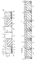
- the structure of Figure 1 has six panels, namely two vertical panels 100, 101; two horizontal panels 102, 103, and two end panels 104, 105. These panels are made of concrete.
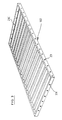
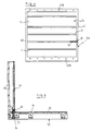
- Each panel consists of a rectangular or square frame formed of beams 4A, 4B, 4C, 4D. Between two opposite beams 4A.4B extend a series of sleepers or ribs 9 so as to define a series of cells 15 between said sleepers or ribs or beams, said beams and said sleepers or ribs being interconnected by a concrete veil 14 with a thickness less than 40 mm forming a flat wall 2, said panels comprising a series of tie rods 19 drowned in concrete.
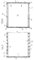
- Each vertical panel 100, 101 has two vertical beams 4D, 4C extending between the lower beam 4B and the upper beam 4A, said beam vertical have a series of passages defined by tubes 23A whose axis is perpendicular to the flat wall of the vertical panel.
- Each end panel 104.105 is placed between the flat walls 2 of said two vertical panels 100, 101, so that the socket openings 20 of a side wall of a first vertical beam of an end panel are located opposite passages defined in a vertical beam 4C, 4D of a first vertical panel, and of so that the socket openings 20 of a wall of the second beam vertical of an end panel are located opposite passages defined in a vertical beam from the second vertical panel.
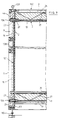
- a series of 106 studs at less partially threaded are introduced into passages 23A of the panels vertical 100. 101 before being screwed into sockets 20 of tie rods 19 of end panels, said studs compressing the flat walls of each vertical panel against a side wall of each end panel.
- the lower beams 4A and upper 4B of the end panel have a series of passages 23B defined by tubes or sockets whose axis is perpendicular to the flat wall 2 of the end panel.
- Each panel horizontal 102,103 has two beams 4C, 4D extending between the panels vertical.
- Said beams have a series of passages 23C defined by tubes or sockets whose axis is parallel to the flat wall of the horizontal panel.
- Said horizontal panels 102, 103 are placed relative to each panel end, so that the openings of sockets or passages 23C of a beam of a first horizontal panel are located opposite passages or sockets 23B of the lower beam 4B of the end panel, and so that that the socket openings or passages 23C of a beam of the second horizontal panel are located opposite passages or sockets 23B of the upper beam 4A of the end panel.
- a layer of glue or concrete extends between the surfaces of contact between the panels.
- the horizontal panels are compressed between the panels vertical by the studs 106 and do not rest by gravity on supports.
- the studs 106 ensure the recovery of the force sharp, and causes significant friction between the concrete walls in contact. The studs are therefore subjected to a shearing force, an effort which is reduced by using the adhesive layer.
- the studs 106 provide traction in the tie rods.
- the horizontal beams or ribs 108 of the vertical panels allow to serve as support for the installation of windows, said sleepers and ribs which can advantageously draw or represent the perimeter of a reservation or other opening.
- the tie rod 19 is located in the vicinity of the joist 21 of the crosspieces or ribs. In the vertical panels, the tie rods are located in the middle of the ribs 9. For horizontal panels whose wall flat is used as a ceiling, the tie rods are close to the flat wall.
- the total thickness of the panels is variable.
- the thickness horizontal panels thickness of the veil + height of the rib
- the thickness vertical panels and end panels are variable.
- the structure has on its upper part a series of openings 22 of vertical panel tie rod bushings. These sockets can be used for fixing of anchor points or lifting rings 107. This facilitates the displacement of structures.
- the bottom of the vertical panels 100,101 of the structure takes advantageously based on a leveling system 110.
- a leveling system 110 is a foot provided with a rod screwed into the tie rod socket, the more or less important screwing of the rod allowing to adjust the position of the foot.
- Such a system can also be used for anchoring two structures according to the invention one above the other.
- the lower beam 4A, the upper beam 4B, as well as the vertical beams 4C, 4D each comprise a series of tubes 23 interconnected by two flat 24 parallel to each other, said tubes 23 extending from the first face 5 of the beam (opening 25 of the tube) to the second face 6 of the beam, said dishes being located along the second face 6 of the beam.
- beams 4C, 4D each have a series of tubes 23 connected together by two flat 24 parallel to each other.
- the axis of said tubes is parallel to the flat wall 2 of the panel.
- the lower and upper beams each have a series of tubes 23 connected to each other by two plates 24 parallel to each other, whose axis is perpendicular to the plane wall 2 of the panel, while the vertical beams 4C, 4D each comprise a series of tubes 23 interconnected by two flat 24 parallel to each other, whose axis is parallel to the flat wall 2 of the panel.
- the height of the vertical panel 100.101 corresponds at the height of the end panel 104.105, while the width of the panel vertical corresponds to the sum of the thicknesses of the end panels and the length of a horizontal panel.
- the widths of the horizontal panels and end panels are identical.
- the tie rods 19 are each connected to a complementary bar 26 by slashes or a zigzag-shaped bar 27.
- the joists 21 and 18 are made of wood and have a tenon 28 in the tail dovetail directed towards the first face of the beam 4 or of a cross member or rib 9. This ensures excellent attachment of the joists to the concrete.
- the sleepers or ribs 9 in concrete are parallel to each other and extend perpendicular to the axial direction of two beams, crosspieces or ribs could have intersect or intersect in such a way as to allow efforts to be taken up again in different directions.
- the panel comprises a trellis 29 extending in the veil 14, as well as in the sleepers or ribs 9 and the beams 4 in the vicinity of their first face.
- the beams 4 are advantageously covered with a rigid plate of insulating material 30, so that the face of the panel 1 opposite to the face 2 of the panel is made of insulating material and wooden joists.
- the insulating material is a rigid expanded material with closed cells, in particular density less than 1.
- structures using a tie rod are used 19, a bar 26 parallel to said tie rod and oblique bars 27 or a bar in zigzag connecting the tie rod to the parallel bar, and at least partially a structure in each transverse channel 205.
- a trellis 29 so that it rests on tie rods or bars structures, said trellis extending above the insulating blocks 17, preferably by not touching them.
- Lattice structures or beams are for example formed by concrete bars parallel to each other, connected at regular intervals by oblique spacers.
- the studs 106 are removed and introduced into tubes 23 attachment means. These attachment means are then connected to a lifting means which, thanks to the membrane 300, allows a release without risk of breakage of the thin web 14.
- the rigid insulating blocks are slightly compressed and therefore adhere firmly to concrete. If necessary, it is possible to withdraw a part or the all of the insulating blocks, for example by milling.
- Transporting the structure to the building construction site we advantageously uses a trailer or semi-trailer.
- the structure is provided on its lower part with a cradle consisting of two cross beams (each attached directly to sockets 22 vertical main panels), a first beam resting directly on the transport plate, while the second beam rests on the transport tray by means of a separate support, which support allows the pivoting of the beam perpendicular to the first beam and in a plane parallel to the transport platform. This provision allows to eliminate torsional forces, which could be caused by the chainring transport.
Landscapes
- Engineering & Computer Science (AREA)
- Architecture (AREA)
- Physics & Mathematics (AREA)
- Electromagnetism (AREA)
- Civil Engineering (AREA)
- Structural Engineering (AREA)
- Mechanical Engineering (AREA)
- Chemical & Material Sciences (AREA)
- Ceramic Engineering (AREA)
- Manufacturing & Machinery (AREA)
- Forms Removed On Construction Sites Or Auxiliary Members Thereof (AREA)
- On-Site Construction Work That Accompanies The Preparation And Application Of Concrete (AREA)
- Panels For Use In Building Construction (AREA)
Claims (13)
- Struktur mit mindestens vier Platten (100, 101, 102, 103) aus Beton, welche in Zweierpaaren miteinander verbunden sind. Dabei besteht jede Platte aus einem rechteckigen oder viereckigen Rahmen aus Balken (4), zwischen denen sich eine Reihe von Querträgem oder Rippen (9) erstrecken, und zwar so dass sie eine Reihe von Waben zwischen besagten Querträgern oder Rippen (9) bilden. Besagte Balken und besagte Querträger oder Rippen sind untereinander durch eine Betonschale (14) mit einer Dicke unter 40 mm in Form einer flachen Wand verbunden. Besagte Platten enthalten eine Reihe von Zugbändern (19), welche im Beton verankert sind. Besagte Struktur besteht aus:(a) zwei vertikalen Platten (100, 101), deren flache Wände (2) gegeneinander gerichtet sind und deren obere und untere Balken (4A,4B) eine Reihe von Übergängen aufweisen, welche durch Rohre (23) entstehen, deren Achse senkrecht zur flachen Wand (2) liegt,(b) zwei horizontalen Platten (102, 103). Jede horizontale Platte (102, 103) enthält Zugbänder (19), welche mit Gewindestücken (20) verbunden sind, welche alle eine Öffnung längs einer Seitenwand eines Balkens aufweisen. Besagte Seitenwand befindet sich senkrecht zur flachen Wand (2) der horizontalen Platte. Besagte horizontale Platten werden zwischen die flachen Wände (2) besagter beider vertikaler Platten (100, 101) gelegt, und zwar so dass die Fassungsöffnungen (20) einer Wand des Balkens einer horizontalen Platte sich gegenüber von Übergängen (23) befinden, die im unteren Balken (4B) oder oberen Balken (4A) einer vertikalen Platte entstehen und(c) einer Reihe von Bolzen (106), welche zumindest teilweise gewindet sind und in die Übergänge (23) der vertikalen Platten (100, 101) eingesetzt werden, bevor sie in die Fassungen (20) der Zugbänder (19) der horizontalen Platten (102, 103) geschraubt werden. Besagte Bolzen (106) drücken die flachen Wände (2) jeder vertikalen Platte gegen eine Seitenwand jeder horizontalen Platte.
- Struktur gemäß Anspruch 1, dadurch gekennzeichnet, dass sie eine oder zwei Endplatten (104, 105) enthält. Jede Endplatte besteht aus einem rechteckigen oder viereckigen Rahmen aus Balken (4A,4B,4C,4D), davon zwei vertikale Balken (4C,4D), zwischen denen sich eine Reihe von Querträgern oder Rippen (9) erstrecken, und zwar so dass sie eine Reihe von Waben (15) zwischen besagten Querträgern oder Rippen oder Balken bilden. Besagte Balken und besagte Querträger oder Rippen sind miteinander durch eine Betonschale (14) mit einer Dicke unter 40 mm in Form einer flachen Wand verbunden. Besagte Platten enthalten eine Reihe von Zugbändern (19), welche im Beton verankert sind und sich zwischen einem ersten vertikalen Balken (4C) und einem zweiten vertikalen Balken (4D) erstrecken;
dadurch gekennzeichnet, dass die Zugbänder (19) einer einzelnen oder jeder Endplatte mit Gewindestücken (20) verbunden sind, welche alle eine Öffnung längs einer Seitenwand eines vertikalen Balkens aufweisen. Besagte Seitenwand liegt senkrecht zur flachen Wand (2) der Endplatte;
dadurch gekennzeichnet, dass jede vertikale Platte (100, 101) mindestens einen vertikalen Balken (4C,4D) aufweist, der sich zwischen dem unteren Balken (4B) und dem oberen Balken (4A) erstreckt. Besagter vertikaler Balken (4C,4D) weist eine Reihe von Übergängen auf, welche durch Rohre (23) entstehen, deren Achse senkrecht zur flachen Wand (2) der vertikalen Platte liegt;
dadurch gekennzeichnet, dass die oder jede Endplatte (104, 105) zwischen die flachen Wände (2) besagter vertikaler Platten (100, 101) eingesetzt wird, und zwar so dass die Fassungsöffnungen (20) einer Seitenwand eines ersten vertikalen Balkens (4D) einer Endplatte sich gegenüber von Übergängen (23) befinden, welche in einem vertikalen Balken (4C) einer ersten vertikalen Platte entstehen. Außerdem befinden sich die Fassungsöffnungen (20) einer Wand des zweiten vertikalen Balkens (4C) einer Endplatte gegenüber von Übergängen (23), welche in einem vertikalen Balken (4D) der zweiten vertikalen Platte entstehen und
dadurch gekennzeichnet, dass eine Reihe von Bolzen (106), welche zumindest teilweise gewindet sind, in die Übergänge (23) der vertikalen Platten (100, 101) eingesetzt werden, bevor sie in die Fassungen (20)
der Zugbänder (19) einer oder jeder Endplatte geschraubt werden. Besagte Bolzen (106) drücken die flachen Wände (2) jeder vertikalen Platte gegen eine Seitenwand der Endplatte oder jeder Endplatte. - Struktur gemäß Anspruch 2, dadurch gekennzeichnet, dass die oder jede Endplatte (104, 105) einen unteren Balken (4B) und einen oberen Balken (4A) aufweist, zwischen denen sich besagter erster und zweiter vertikaler Balken (4C,4D) der Endplatte erstrecken;
dadurch gekennzeichnet, dass besagter unterer und oberer Balken (4B,4A) der Endplatte (104, 105) eine Reihe von Übergängen (23) aufweisen, welche durch Rohre oder Fassungen entstehen, deren Achse sich senkrecht zur flachen Wand der Endplatte befindet;
dadurch gekennzeichnet, dass jede horizontale Platte (102, 103) einen Balken (4C,4D) enthält, der eine Reihe von Übergängen (23) aufweist, welche durch Rohre oder Fassungen entstehen, deren Achse sich parallel zur flachen Wand der horizontalen Platte befindet. Besagte horizontale Platten werden bezogen auf die Endplatte (104, 105) oder auf jede Endplatte eingesetzt. Dies erfolgt so, dass sich die Fassungsöffnungen oder Übergänge (23) eines Balkens (4D) einer ersten horizontalen Platte (102) gegenüber von Übergängen (23) oder Fassungen des unteren Balkens (4B) der Endplatte (104) befinden und sich die Fassungsöffnungen oder Übergänge (23) eines Balkens (4D) der zweiten horizontalen Platte (103) gegenüber von Übergängen (23) oder Fassungen des oberen Balkens (4A) der Endplatte befinden. - Betonplatte (1), welche eine flache Wand (2) für eine Struktur gemäß einem der Ansprüche 1 bis 3 aufweist. Diese Platte besteht aus einem Betonelement, das gebildet wird aus:vier Betonbalken (4A,4B,4C,4D), welche einen viereckigen oder rechteckigen Rahmen entstehen lassen. Besagte Balken sind paarweise parallel zueinander angeordnet und weisen jeder eine erste Seite (5) auf, welche einen Teil der flachen Wand (2) der Platte bildet. Außerdem weisen sie eine zweite Seite (6) gegenüber der ersten Seite (5), eine laterale Innenseite (7) in Richtung eines anderen Balken und eine laterale Außenseite (8) auf, welche gegenüber der lateralen Innenseite (7) liegt;mindestens zwei Querträgern oder Rippen oder Rippen (9) aus Beton, welche sich zwischen zwei parallel zueinander liegenden Balken (4A, 4B, 4C, 4D) erstrecken und jeder eine erste Seite (10) aufweisen, welche einen Teil der flachen Wand (2) der Platte (1), eine zweite Seite (11) gegenüber der ersten Seite (10), eine laterale Seite (12) in Richtung eines Querbalkens oder einer angrenzenden Rippe (9) und eine Seite (13) gegenüber besagter lateraler Seite (12) bildet;einer Betonschale mit einer Dicke unter 40 mm, im Idealfall unter 30 mm, zwischen den Querträgern oder Rippen (9) und/oder den Balken (4) unmittelbar bei ihrer ersten Seite (5,10). Diese Betonschale (14) bildet mit besagten ersten Seiten (5,10) der Querträger oder Rippen und Balken die flache Wand (2) der Platte (1) sowie Schalen (15), welche zwischen den Querträgern oder Rippen und Balken entstehen. Der Boden besagter Schalen (15) wird durch die flache Wand (2) der Platte (1) gebildet, besagte Schalen (15) werden nach Möglichkeit mit Isoliermaterial (17) gefüllt;mindestens einem Bodenbalken (18) für jeden Balken. Der oder die besagten Bodenbalken jedes Balken werden von der zweiten Seite (6) des Balkens getragen;mindestens einem Bodenbalken (21) für die Mehrheit der Querträger oder Rippen (9). Der oder die besagten Bodenbalken eines Querträgers oder Rippe (9) werden von der zweiten Seite (11) des Querträgers oder der Rippe (9) getragen;Zugbändern (19), welche zwei zueinander parallel (4) liegende Balken (4A,4B) mit Querträgern oder Rippen (9) verbinden;mindestens einem Gewindestück (20) für jedes Zugband (19), welches einen Balken (4) mit einem Querträger oder einer Rippe (9) verbindet. Besagte Fassung (20) weist eine Öffnung (22) auf, welche gegen die laterale Außenseite (8) des Balkens (4A,4B) gerichtet ist.
- Betonplatte gemäß Anspruch 4, dadurch gekennzeichnet, dass die Betonschale (14) eine Dicke zwischen 10 und 30 mm aufweist, diese Dicke liegt vorzugsweise zwischen 15 und 25 mm.
- Betonplatte gemäß Anspruch 4 oder 5, dadurch gekennzeichnet, dass jeder Querträger oder jede Rippe (9) aus Beton durch das gleiche Zugband (19) mit den beiden zueinander parallel liegenden Balken (4A, 4B) verbunden ist.
- Betonplatte gemäß einem der Ansprüche 4 bis 6, dadurch gekennzeichnet, dass jedes Zugband (19) mit einer Zusatzstange (26) durch Schrägstangen (27) oder durch eine zickzackförmige Stange verbunden ist.
- Betonplatte gemäß einem der Ansprüche 4 bis 7, dadurch gekennzeichnet, dass sie ein Gittergeflecht (29) enthält, welche sich in der Schale (14) sowie in den Querträgern oder Rippen (9) und den Balken (4A, 4B, 4C, 4D) unmittelbar neben ihrer ersten Seite (5) erstreckt.
- Betonplatte gemäß einem der Ansprüche 4 bis 8, dadurch gekennzeichnet, dass zwei zueinander parallel liegende Balken (4A,4B) jeweils beide eine Reihe von Rohren (23) enthalten, welche untereinander durch mindestens eine Flachstange (24) verbunden sind. Besagte Rohre (23) erstrecken sich von der ersten Seite (5) des Balkens (4) bis zur zweiten Seite (6) des Balkens (4).
- Betonplatte gemäß Anspruch 9, dadurch gekennzeichnet, dass die Rohre (23), welche sich in einem Balken (4A,4B) erstrecken, miteinander durch zwei parallel angeordnete Flachstangen (24) verbunden sind. Außerdem befinden sich die Flachstangen (24), welche die Rohre (23) miteinander verbinden, entlang der zweiten Seite (6) des Balkens (4A,4B).
- Betonplatte gemäß einem der Ansprüche 4 bis 10, dadurch gekennzeichnet, dass die Schalen (15), welche zwischen den Balken (4) und Querträgern oder Rippen (9) entstanden sind, einen Block aus Isoliermaterial (17) enthalten und die zweite Seite (6) der Balken (4A,4B) mit einer Platte oder einem Block aus Isoliermaterial (30) versehen ist, welche sich zwischen einem Bodenbalken (18) und dem Block oder der Platte (30) erstrecken, welche in eine Schale (15) gelegt wurden.
- Plattenherstellungsverfahren gemäß Anspruch 11. Dabei wird Beton in eine Form (200) mit einem Boden (201) und Seitenwänden (202) gegossen, welche mit dem Boden zusammen eine Schale bilden, dadurch gekennzeichnet, dassder Boden (201) der Form mit einer Membran abgedeckt wird, welche vorzugsweise wabenförmig und möglichst mit der Zeichnung oder einer Markierung versehen ist, welche die Bestandteile der Platte (300) darstellen. Dabei wird zwischen der gegossenen Platte und dem Boden der Form eine Luftzirkulation gewährleistet;auf der Membran Bodenbalken (18) und Blöcke oder Platten (30) aus steifem Isoliermaterial abgelegt werden, deren Dicke wenigstens unter der Dicke der Bodenbalken (18) liegt oder mit dieser identisch ist. Dabei entstehen die Böden beider Hauptkanäle (204) für den Guss der beiden ersten zueinander parallel liegenden Balken (4). Die Bodenbalken (21) werden zur Bildung der Böden der Gusskanäle (205) der Querträger oder Rippen (9) eingesetzt;auf der Membran zwischen den Hauptgusskanälen der Balken (4) und den Rippen und Querträgern (9) Blöcke (17) aus Isoliermaterial eingesetzt werden, welches eine Dicke aufweist, die mindestens über der Dicke des Bodenbalkens (21) der Querträger oder Rippen legt;eventuell auf dem Boden jeder der beiden Hauptkanäle (204) eine Reihe von Rohren (23) gelegt wird, welche durch eine oder zwei Flachstangen (24) miteinander verbunden sind. Die Rohre (23) erstrecken sich von unten nach oben in besagten Kanälen von deren Boden aus;in die quer liegenden Kanäle (205) oder unmittelbar oberhalb der querliegenden Kanäle ein Zugband (19) oder Zugbänder (19) eingesetzt werden, welche mit einem oder mehreren Gewindestücken (20) versehen sind. In die Öffnungen (203), welche die Seitenwände der Form aufweisen, werden Bolzen (106) eingesetzt. Besagte Bolzen werden in die Fassungen der Zugbänder (19) geschraubt, damit die Zugbänder (19) an derselben Stelle verbleiben und die Fassungen (20) jeweils gegen eine Seitenwand (202) der Form angebracht werden;in die Hauptkanäle (204) und die quer liegenden Kanäle (205) sowie oberhalb der Blöcke aus Isoliermaterial (17) Beton gegossen wird. Die Menge des eingegossenen Betons ist so bemessen, dass die Dicke der oberhalb der Blöcke gebildeten Betonschale (14) unter 40 mm beträgt;die Form Vibrationen ausgesetzt wird undnach der teilweisen Abbindung des Betons die Bolzen (106) entfernt und die entstandene Platte aus der Form genommen werden.
- Verfahren gemäß Anspruch 12, dadurch gekennzeichnet, dass eine ausreichende Betonmenge zur Erhaltung einer Betonschale (14) oberhalb der Blöcke (17) eingegossen wird, welche eine Dicke zwischen 10 und 30 mm, im Idealfall zwischen 15 und 25 mm aufweisen.
Applications Claiming Priority (3)
| Application Number | Priority Date | Filing Date | Title |
|---|---|---|---|
| BE9600290 | 1996-04-05 | ||
| BE9600290A BE1010092A6 (fr) | 1996-04-05 | 1996-04-05 | Procede de fabrication et d'assemblage d'un element de contruction en beton. |
| PCT/BE1997/000041 WO1997038179A1 (fr) | 1996-04-05 | 1997-04-04 | Structure, panneau pour une telle structure et sa fabrication |
Publications (2)
| Publication Number | Publication Date |
|---|---|
| EP0891458A1 EP0891458A1 (de) | 1999-01-20 |
| EP0891458B1 true EP0891458B1 (de) | 2001-01-10 |
Family
ID=3889649
Family Applications (1)
| Application Number | Title | Priority Date | Filing Date |
|---|---|---|---|
| EP97916276A Expired - Lifetime EP0891458B1 (de) | 1996-04-05 | 1997-04-04 | Baustruktur, panel für eine solche baustruktur und seine herstellung |
Country Status (4)
| Country | Link |
|---|---|
| EP (1) | EP0891458B1 (de) |
| BE (1) | BE1010092A6 (de) |
| DE (1) | DE69703881D1 (de) |
| WO (1) | WO1997038179A1 (de) |
Families Citing this family (5)
| Publication number | Priority date | Publication date | Assignee | Title |
|---|---|---|---|---|
| DE20215395U1 (de) * | 2002-10-07 | 2003-03-13 | Betonbau GmbH, 68753 Waghäusel | Transportable Raumzelle zum Schutz einer Senderanlage oder anderer elektronischer Geräte |
| FR2857391B1 (fr) * | 2003-07-07 | 2012-01-20 | Marc Louis | Panneau et sa fabrication |
| ES2284306B1 (es) | 2005-03-03 | 2008-09-16 | Compact-Habit, S.L. | Sistema de construccion modular. |
| CN101769039A (zh) * | 2010-03-16 | 2010-07-07 | 商清 | 一种新型建筑物构件组合件 |
| CN110924533B (zh) * | 2019-12-03 | 2021-02-09 | 湖南建工集团有限公司 | 一种钢骨架泡沫混凝土组合结构单元房 |
Family Cites Families (7)
| Publication number | Priority date | Publication date | Assignee | Title |
|---|---|---|---|---|
| US2616282A (en) * | 1950-05-11 | 1952-11-04 | Frank W Vogel | Concrete building construction |
| DE2431424C2 (de) * | 1974-06-29 | 1985-01-31 | Lorenz 4600 Dortmund Kesting | Verfahren zum Herstellen einer einseitig offenen Stahlbetonraumzelle und Bausatz zur Durchführung des Verfahrens |
| US4422997A (en) * | 1978-12-14 | 1983-12-27 | Alfred Machnik | Method for making an insulated panel |
| CH654614A5 (en) * | 1983-04-11 | 1986-02-28 | Selam Sa | Precast reinforced-concrete wall or floor element with built-in insulation |
| WO1986005227A1 (fr) * | 1985-03-01 | 1986-09-12 | Philippe Boelen | Procede de montage d'elements prefabriques, elements prefabriques et batiments edifies selon le procede |
| FR2631056B1 (fr) * | 1988-05-09 | 1992-05-07 | Rech Etudes Tech | Element de construction en beton precontraint, du type predalle, et installation pour sa fabrication |
| US5313753A (en) * | 1991-08-27 | 1994-05-24 | Sanger Wallace D | Construction wall panel and panel structure |
-
1996
- 1996-04-05 BE BE9600290A patent/BE1010092A6/fr not_active IP Right Cessation
-
1997
- 1997-04-04 WO PCT/BE1997/000041 patent/WO1997038179A1/fr not_active Ceased
- 1997-04-04 DE DE69703881T patent/DE69703881D1/de not_active Expired - Lifetime
- 1997-04-04 EP EP97916276A patent/EP0891458B1/de not_active Expired - Lifetime
Also Published As
| Publication number | Publication date |
|---|---|
| DE69703881D1 (de) | 2001-02-15 |
| WO1997038179A1 (fr) | 1997-10-16 |
| EP0891458A1 (de) | 1999-01-20 |
| BE1010092A6 (fr) | 1997-12-02 |
Similar Documents
| Publication | Publication Date | Title |
|---|---|---|
| WO2007048836A1 (fr) | Nouveau type de batiment, procede et moyens pour sa realisation | |
| EP0891458B1 (de) | Baustruktur, panel für eine solche baustruktur und seine herstellung | |
| CA2291591A1 (fr) | Ossature de batiment | |
| FR2556387A1 (fr) | Element de construction du type en polystyrene expanse, destine a la realisation de mur | |
| FR3126234A1 (fr) | Panneau mural et procédé de fabrication d’un tel panneau mural | |
| EP0464008B1 (de) | Modulares, mit einer Putzschicht überzogenes und mit benachbarten Elementen verbindbares Schaumstoffelement und Verfahren zum Formen einer Putzschicht und Aufbau einer Wand | |
| WO2009092890A2 (fr) | Elément modulaire préfabriqué de plancher sec, procédé de fabrication d'un tel élément modulaire et plancher sec comprenant une pluralité d'éléments modulaires | |
| EP0031171B1 (de) | Verfahren zur Erstellung eines Gebäudes mittels isolierter Platten nach dem System der verlorenen Schalung | |
| CA2655169A1 (fr) | Panneau prefabrique pour construction de batiment et procede de fabrication d'un tel panneau | |
| EP0826840A1 (de) | Bauzelle | |
| FR2729411A3 (fr) | Dalle coffrante nervuree legere en beton arme pour plancher dalle-pleine et son procede de fabrication | |
| FR2885624A1 (fr) | Procede de construction d'un batiment prefabrique et element constitutif de ce batiment | |
| FR2614052A1 (fr) | Elements de construction prefabriques en beton arme, procede de fabrication de ceux-ci et murs obtenus | |
| FR2927339A1 (fr) | Ossature modulaire pour la construction de batiment | |
| FR2857391A1 (fr) | Panneau et sa fabrication | |
| FR2918395A1 (fr) | Immeuble et procede de construction d'un immeuble | |
| FR2530705A1 (fr) | Elements de construction pour la prefabrication notamment de planchers | |
| EP0145062A2 (de) | Industrialisiertes Verfahren zur Errichtung von Mauerwerk aus Terrakotta und Zement und Blöcke für die Durchführung dieses Verfahrens | |
| EP1359263A1 (de) | Baumodul mit zwei zusammengesetzten Paneelen | |
| FR2805555A1 (fr) | Coffrage perdus alveolaires pour la construction de murs et de planchers et procedes de fabrication et de mise en oeuvre desdits coffrages | |
| EP4536909A1 (de) | Bauwerk mit doppelrahmen aus beton | |
| FR2802559A1 (fr) | Coffrage isolant permanent avec cadres de jonction | |
| WO2001053624A1 (fr) | Procede de construction d'un edifice, bloc de construction, linteau et appui de fenetre pour la mise en oeuvre du procede | |
| FR2516962A1 (fr) | Dispositif de construction comportant des panneaux-modules de planchers auto-coffrants | |
| BE859083A (fr) | Procede de realisation d'un mur ou d'une fondation armee |
Legal Events
| Date | Code | Title | Description |
|---|---|---|---|
| PUAI | Public reference made under article 153(3) epc to a published international application that has entered the european phase |
Free format text: ORIGINAL CODE: 0009012 |
|
| 17P | Request for examination filed |
Effective date: 19981001 |
|
| AK | Designated contracting states |
Kind code of ref document: A1 Designated state(s): BE DE FR GB IT NL |
|
| GRAG | Despatch of communication of intention to grant |
Free format text: ORIGINAL CODE: EPIDOS AGRA |
|
| 17Q | First examination report despatched |
Effective date: 19991123 |
|
| GRAG | Despatch of communication of intention to grant |
Free format text: ORIGINAL CODE: EPIDOS AGRA |
|
| GRAH | Despatch of communication of intention to grant a patent |
Free format text: ORIGINAL CODE: EPIDOS IGRA |
|
| GRAH | Despatch of communication of intention to grant a patent |
Free format text: ORIGINAL CODE: EPIDOS IGRA |
|
| GRAA | (expected) grant |
Free format text: ORIGINAL CODE: 0009210 |
|
| AK | Designated contracting states |
Kind code of ref document: B1 Designated state(s): BE DE FR GB IT NL |
|
| PG25 | Lapsed in a contracting state [announced via postgrant information from national office to epo] |
Ref country code: NL Free format text: LAPSE BECAUSE OF FAILURE TO SUBMIT A TRANSLATION OF THE DESCRIPTION OR TO PAY THE FEE WITHIN THE PRESCRIBED TIME-LIMIT Effective date: 20010110 Ref country code: IT Free format text: LAPSE BECAUSE OF FAILURE TO SUBMIT A TRANSLATION OF THE DESCRIPTION OR TO PAY THE FEE WITHIN THE PRE;WARNING: LAPSES OF ITALIAN PATENTS WITH EFFECTIVE DATE BEFORE 2007 MAY HAVE OCCURRED AT ANY TIME BEFORE 2007. THE CORRECT EFFECTIVE DATE MAY BE DIFFERENT FROM THE ONE RECORDED.SCRIBED TIME-LIMIT Effective date: 20010110 Ref country code: GB Free format text: LAPSE BECAUSE OF FAILURE TO SUBMIT A TRANSLATION OF THE DESCRIPTION OR TO PAY THE FEE WITHIN THE PRESCRIBED TIME-LIMIT Effective date: 20010110 |
|
| REF | Corresponds to: |
Ref document number: 69703881 Country of ref document: DE Date of ref document: 20010215 |
|
| PG25 | Lapsed in a contracting state [announced via postgrant information from national office to epo] |
Ref country code: DE Free format text: LAPSE BECAUSE OF FAILURE TO SUBMIT A TRANSLATION OF THE DESCRIPTION OR TO PAY THE FEE WITHIN THE PRESCRIBED TIME-LIMIT Effective date: 20010411 |
|
| NLV1 | Nl: lapsed or annulled due to failure to fulfill the requirements of art. 29p and 29m of the patents act | ||
| GBV | Gb: ep patent (uk) treated as always having been void in accordance with gb section 77(7)/1977 [no translation filed] |
Effective date: 20010110 |
|
| PLBE | No opposition filed within time limit |
Free format text: ORIGINAL CODE: 0009261 |
|
| STAA | Information on the status of an ep patent application or granted ep patent |
Free format text: STATUS: NO OPPOSITION FILED WITHIN TIME LIMIT |
|
| 26N | No opposition filed | ||
| REG | Reference to a national code |
Ref country code: FR Ref legal event code: ST |
|
| REG | Reference to a national code |
Ref country code: FR Ref legal event code: RN |
|
| REG | Reference to a national code |
Ref country code: FR Ref legal event code: D3 |
|
| REG | Reference to a national code |
Ref country code: FR Ref legal event code: ST |
|
| REG | Reference to a national code |
Ref country code: FR Ref legal event code: RN |
|
| REG | Reference to a national code |
Ref country code: FR Ref legal event code: FC |
|
| REG | Reference to a national code |
Ref country code: FR Ref legal event code: ST Effective date: 20081231 |
|
| PGRI | Patent reinstated in contracting state [announced from national office to epo] |
Ref country code: FR Effective date: 20040131 |
|
| PGRI | Patent reinstated in contracting state [announced from national office to epo] |
Ref country code: FR Effective date: 20091214 |
|
| PGFP | Annual fee paid to national office [announced via postgrant information from national office to epo] |
Ref country code: FR Payment date: 20100507 Year of fee payment: 14 |
|
| REG | Reference to a national code |
Ref country code: FR Ref legal event code: ST Effective date: 20111230 |
|
| PG25 | Lapsed in a contracting state [announced via postgrant information from national office to epo] |
Ref country code: FR Free format text: LAPSE BECAUSE OF NON-PAYMENT OF DUE FEES Effective date: 20110502 |
|
| REG | Reference to a national code |
Ref country code: FR Ref legal event code: RN Effective date: 20130819 |
|
| REG | Reference to a national code |
Ref country code: FR Ref legal event code: IC Effective date: 20131126 |
|
| PGFP | Annual fee paid to national office [announced via postgrant information from national office to epo] |
Ref country code: BE Payment date: 20140430 Year of fee payment: 18 |
|
| PG25 | Lapsed in a contracting state [announced via postgrant information from national office to epo] |
Ref country code: BE Free format text: LAPSE BECAUSE OF NON-PAYMENT OF DUE FEES Effective date: 20150430 |