EP0891485B1 - Vergaser brennstoffdüse - Google Patents
Vergaser brennstoffdüse Download PDFInfo
- Publication number
- EP0891485B1 EP0891485B1 EP97902962A EP97902962A EP0891485B1 EP 0891485 B1 EP0891485 B1 EP 0891485B1 EP 97902962 A EP97902962 A EP 97902962A EP 97902962 A EP97902962 A EP 97902962A EP 0891485 B1 EP0891485 B1 EP 0891485B1
- Authority
- EP
- European Patent Office
- Prior art keywords
- carburetor
- orifice
- downstream
- upstream
- fuel
- Prior art date
- Legal status (The legal status is an assumption and is not a legal conclusion. Google has not performed a legal analysis and makes no representation as to the accuracy of the status listed.)
- Expired - Lifetime
Links
- 239000000446 fuel Substances 0.000 title claims description 98
- 238000011144 upstream manufacturing Methods 0.000 claims description 33
- 238000000889 atomisation Methods 0.000 claims description 3
- 229910001369 Brass Inorganic materials 0.000 description 3
- 239000010951 brass Substances 0.000 description 3
- 238000002485 combustion reaction Methods 0.000 description 3
- 239000004033 plastic Substances 0.000 description 3
- 229920003023 plastic Polymers 0.000 description 3
- 229920004943 Delrin® Polymers 0.000 description 2
- 239000000463 material Substances 0.000 description 2
- 239000007769 metal material Substances 0.000 description 2
- 238000012986 modification Methods 0.000 description 2
- 230000004048 modification Effects 0.000 description 2
- DHKHKXVYLBGOIT-UHFFFAOYSA-N 1,1-Diethoxyethane Chemical compound CCOC(C)OCC DHKHKXVYLBGOIT-UHFFFAOYSA-N 0.000 description 1
- 239000011354 acetal resin Substances 0.000 description 1
- 238000004891 communication Methods 0.000 description 1
- 230000001419 dependent effect Effects 0.000 description 1
- 239000012530 fluid Substances 0.000 description 1
- 238000004519 manufacturing process Methods 0.000 description 1
- 239000002184 metal Substances 0.000 description 1
- 229910052751 metal Inorganic materials 0.000 description 1
- 150000002739 metals Chemical class 0.000 description 1
- 238000000034 method Methods 0.000 description 1
- 229920006324 polyoxymethylene Polymers 0.000 description 1
- 238000010008 shearing Methods 0.000 description 1
Images



Classifications
-
- F—MECHANICAL ENGINEERING; LIGHTING; HEATING; WEAPONS; BLASTING
- F02—COMBUSTION ENGINES; HOT-GAS OR COMBUSTION-PRODUCT ENGINE PLANTS
- F02M—SUPPLYING COMBUSTION ENGINES IN GENERAL WITH COMBUSTIBLE MIXTURES OR CONSTITUENTS THEREOF
- F02M19/00—Details, component parts, or accessories of carburettors, not provided for in, or of interest apart from, the apparatus of groups F02M1/00 - F02M17/00
- F02M19/03—Fuel atomising nozzles; Arrangement of emulsifying air conduits
-
- F—MECHANICAL ENGINEERING; LIGHTING; HEATING; WEAPONS; BLASTING
- F02—COMBUSTION ENGINES; HOT-GAS OR COMBUSTION-PRODUCT ENGINE PLANTS
- F02M—SUPPLYING COMBUSTION ENGINES IN GENERAL WITH COMBUSTIBLE MIXTURES OR CONSTITUENTS THEREOF
- F02M7/00—Carburettors with means for influencing, e.g. enriching or keeping constant, fuel/air ratio of charge under varying conditions
- F02M7/02—Carburettors having aerated fuel spray nozzles
Definitions
- the present invention generally relates to the field of carburetors that mix air and fuel for internal combustion engines and, more particularly, to the field of fuel nozzles that provide fuel to the throat of such carburetors.
- French reference FR-E-26,901 discloses a fuel nozzle (1) having a pair of upstream orifices (2) and which is interconnected to a fuel conduit (5).
- French reference FR-A-555,986 discloses a fuel nozzle (1) disposed in a carburetor and in fluid communication with a fuel line (6).
- Another background art reference is British reference GB-A-649,920, which discloses a fuel nozzle (13) having an upstream orifice (24) and a downstream orifice (23) disposed within a carburetor. The fuel nozzle is angled with respect to the flow of air through the carburetor, and fuel within the fuel nozzle blocks the upstream orifice (24) during high suction and low engine speeds.
- Another background art reference is British reference GB-A-148,507, which discloses a fuel nozzle or choke tube (g) having an air inlet orifice (k) and a orifice for the outflow of fuel (k1). Fuel is drawn through the choke tube (g) from a chamber (d) containing a constant level (indicated by line 1-1) of fuel.
- Another background art reference is GB-A-224 719 which discloses a carburetor according to the preamble of claim 1.
- Fuel is typically provided to the air by a fuel nozzle that is operatively interconnected with a fuel supply (e.g., a fuel bowl).
- the fuel nozzle extends transversely into the carburetor throat, and includes an outlet port in a tip thereof.
- the outlet port commonly faces transverse to the air flow such that air passing over the port will create a negative pressure, thereby resulting in fuel being drawn from fuel nozzle.
- air can also flow in the reverse direction (i.e., from the combustion chamber toward the carburetor intake), sometimes called "reverse flow.”
- Reverse flow is typically caused by intake valve leakage, which can result from valve lash, inconsistent cam profiles or poor valve seals. Due to the presence of an air velocity, reverse flow creates a negative pressure at the outlet port, resulting in fuel being drawn from the fuel nozzle. When forward flow resumes, fuel is again drawn from the fuel nozzle, resulting in a "double charge” of fuel. This double charge creates an air/fuel ratio that is richer than the optimum air/fuel ratio of the carburetor, resulting in excess emissions and lower fuel economy.
- a carburetor for use in an engine comprises a carburetor body (22) having a throat (24) extending from an intake (26) to a discharge (28), wherein a downstream direction is defined as extending from said intake toward said discharge, and wherein an upstream direction is defined as extending from said discharge toward said intake; and a fuel nozzle (32) having body, said body having a longitudinal axis positioned within said throat such that said longitudinal axis is substantially normal to said upstream and downstream directions, said nozzle including at least one upstream orifice (39) facing substantially upstream and at least one downstream orifice (40, 42, or 44) facing substantially downstream, said at least one upstream orifice being positioned closer to the carburetor body than said at least one downtstream orifice, characterized in
- Fig. 1 is a side section view of a carburetor embodying the present invention and including a fuel nozzle.
- Fig. 2 is a longitudinal section view of the fuel nozzle illustrated in Fig. 1.
- Fig. 3 is a section view of the fuel nozzle taken along line 3-3 in Fig. 2.
- Fig. 4 is an end view of the fuel nozzle taken along line 4-4 in Fig. 2.
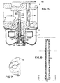
- Fig. 5 is a side section view of a different carburetor embodying the present invention and including a fuel nozzle.
- Fig. 6 is a longitudinal section view of the fuel nozzle illustrated in Fig. 5.
- Fig. 7 is an end view of the fuel nozzle taken along line 7-7 in Fig. 6.
- Figs. 8-12 illustrate various fuel nozzles embodying the present invention.
- Fig. 1 illustrates a carburetor 20 having a carburetor body 22 with a carburetor throat 24 extending therethrough from an intake region 26 to a discharge region 28.
- the carburetor 20 further includes a throttle 30 that regulates the amount of air and fuel passing through the throat 24.
- a fuel nozzle 32 is positioned to provide fuel to the throat 24.
- the fuel nozzle 32 generally includes a base 34 mounted to the carburetor body 22, and a tip 36 extending from the base 34, through a carburetor wall 37, and at least partially positioned within the carburetor throat.
- the tip 36 is provided with an upstream orifice and at least one downstream orifice having a surface area larger than a surface area of the upstream orifice.
- surface area is used to describe the orifice's propensity to discharge fuel. That is, the larger the surface area of the orifice, the more fuel it is likely to discharge given a particular pressure.
- the surface area values used herein refer to the area of the orifice at the outer surface of the fuel nozzle. It should be appreciated, of course, that other techniques could be used to achieve the present invention. For example, by using narrow slot-shaped or pinhole openings, surface tension could also play a role in an orifice's propensity to dispense fuel. Further, orifices that change in area from the surface inward could also affect the orifice's performance.
- the tip includes one upstream orifice 38 that is circular and has a diameter of about 0,5334 mm (.021 inches), corresponding with a cross-sectional surface area of about 0,226 square mm (.00035 square inches).
- the illustrated embodiment includes three downstream orifices 40,42,44 that are each circular and have a diameter of about 0,9398 mm (.037 inches), corresponding with a total cross-sectional surface area of about 2,084 square mm (.00323 square inches). It should be appreciated that the orifices do not need to be round in cross-section, and could instead be configured in other appropriate shapes.
- the middle downstream orifice 42 is approximately centered with respect to the throat 24, and the other two downstream orifices 40,44 are equally spaced on either side of the middle downstream orifice 42. Accordingly, the downstream orifices 40,42,44 are positioned in a pattern that is evenly distributed across the throat 24.
- the upstream orifice 38 is positioned off-center with respect to the throat 24. More specifically, the upstream orifice 38 is positioned closer to the carburetor wall 37 than any of the downstream orifices 40,42,44, as shown in Figs. 1 and 2.
- double charging is significantly reduced. More specifically, forward flow will create a low pressure at the downstream orifices, resulting in fuel being dispensed through the downstream orifices. During reverse flow, a high pressure is formed at the downstream orifices, resulting in little or no fuel being dispenses through the downstream orifices. Accordingly, double charging is significantly reduced.
- the positioning of the upstream orifice allows air to enter the fuel nozzle at a right angle to the flow of fuel in the nozzle during forward flow.
- the right angle motion of the air relative to the fuel causes shearing of the fuel in the fuel nozzle, resulting in better fuel atomization as the fuel and air exit the downstream orifices. Because of the small surface area of the upstream orifice relative to the downstream orifices, reverse flow will not result in significant dispersal of fuel through the upstream orifice.
- the fuel nozzle 32 includes a tip 36 and a base 34.
- the tip 36 and the base 34 can be made from a wide variety of materials, including metals and plastics.
- the tip 36 and the base 34 are machined from metallic material, such as SAE CA 332 Brass, and the base 34 is press fit into the tip 36.
- the utilization of a two-piece fuel nozzle facilitates production of a fuel nozzle 32 having a tip 36 with a thinner wall than the base 34. The thinner wall allows the tip to occupy less space within the throat, thereby improving engine performance.
- the base 34 includes a flat surface 46 that corresponds with a flat segment 48 on the tip 36, as shown in Fig. 3.
- the base 34 includes a flat portion 50 that matches the shape of the carburetor body 22, as shown in Fig. 4.
- the carburetor 60 illustrated in Fig. 5 includes an integral fuel bowl 62 and associated float 64 for providing fuel to the carburetor throat 66 via a metering orifice 68 and a fuel nozzle 70.
- the fuel nozzle 70 is a one-piece design made from plastic, such as acetal resin.
- the lower portion of the fuel nozzle includes a D-shaped base portion 72, as shown in Fig. 7, to insure proper alignment of the fuel nozzle 70 with the carburetor body 74.
- Fig. 8 illustrates another fuel nozzle 80 embodying the present invention.
- the fuel nozzle 80 is a two-piece design, including a tip 82 and a base 84.
- the tip 82 and the base 84 are both made of plastic material, such as Delrin, a trademark of E.I. Du Pont De Nemours of Wilmington, Delaware.
- the tip 82 and the base 84 are interconnected by a snap fit, wherein a ridge 86 on the tip 82 fits into a groove 88 on the base 84.
- the tip 82 has a wall thickness that is about the same as the wall thickness of the base 84.
- Fig. 9 illustrates another fuel nozzle 90 embodying the present invention.
- the illustrated fuel nozzle 90 is a one-piece design that is machined from a metallic material, such as brass. A tip portion 92 of the fuel nozzle 90 is blocked by a ball plug 94.
- Fig. 10 illustrates a fuel nozzle 100 embodying the present invention. Similar to the fuel nozzle illustrated in Fig. 8, the fuel nozzle 100 of Fig. 10 is a two-piece Delrin design wherein a tip 102 is snap fit with a base 104. The end of the tip 102 includes a ball plug 106 integrally formed therewith via a flexible interconnecting member 108. The open end of the tip 102 can be selectively closed by inserting the ball plug 106 into the open end.
- Fig. 11 illustrates another fuel nozzle 110 embodying the present invention.
- the fuel nozzle 110 is identical to that illustrated in Fig. 8, except the tip 112 has a wall thickness that is significantly thinner than the wall thickness of the base 114.
- Fig. 12 illustrates a two-piece brass fuel nozzle 120 having a tip 122 and a base 124 press fit into the tip 122.
- the tip 122 illustrated in Fig. 12 extends only partially (e.g., less than halfway) into the carburetor throat 126.
- the tip 122 illustrated in Fig. 12 includes only one downstream orifice 128, rather than the three downstream orifices illustrated in the other fuel nozzles.
- the downstream orifice 128 has a cross-sectional surface area that is significantly larger than the surface area of the upstream orifice 130.
Landscapes
- Engineering & Computer Science (AREA)
- Chemical & Material Sciences (AREA)
- Combustion & Propulsion (AREA)
- Mechanical Engineering (AREA)
- General Engineering & Computer Science (AREA)
- Control Of The Air-Fuel Ratio Of Carburetors (AREA)
- Nozzles (AREA)
Claims (11)
- Vergaser (20) für einen Motor, wobei der Vergaser aufweist:einen Vergaserkörper (22), der einen Hals (24) hat, der sich von einem Einlaß (26) bis zu einem Auslaß (28) erstreckt, wobei die Stromabwärtsrichtung als die Richtung von dem Einlaß nach dem Auslaß definiert ist, und wobei die Stromaufwärtsrichtung als die Richtung von dem Auslaß nach dem Einlaß definiert ist; undeine Kraftstoffdüse (32, 70, 80, 100, 120), die einen Körper hat, wobei der Körper eine Längsachse hat, die innerhalb des Halses so positioniert ist, daß sie im wesentlichen senkrecht zu der Stromaufwärtsrichtung und der Stromabwärtsrichtung ist, wobei die Düse mindestens eine Stromaufwärtsöffnung (38, 130) hat, die im wesentlichen stromaufwärts gerichtet ist, und mindestens eine Stromabwärtsöffnung (40, 42, 44 oder 128) hat, die im wesentlichen stromabwärts gerichtet ist, wobei die mindestens eine Stromaufwärtsöffnung näher bei dem Vergaserkörper positioniert ist als die mindestens eine Stromabwärtsöffnung, dadurch gekennzeichnet, daßdie Mantelfläche der mindestens einen Stromaufwärtsöffnung kleiner als ungefähr 50 Prozent der mindestens einen Stromabwärtsöffnung ist, wodurch die Stromaufwärtsöffnung so dimensioniert und positioniert ist, daß während der Stromabwärtsströmung der Luft in dem Vergaserhals Luft unter einem rechten Winkel zu dem Kraftstoffluß in der Kraftstoffdüse in die Kraftstoffdüse eindringen kann, um während des normalen Betriebs des Motors eine verbesserte Kraftstoffzerstäubung in der Kraftstoffdüse zu bewirken, bevor der Kraftstoff und die Luft die Stromabwärtsöffnung verlassen.
- Vergaser wie in Anspruch 1 beansprucht, wobei die Mantelfläche der mindestens einen Stromaufwärtsöffnung kleiner als ungefähr 25 Prozent der Mantelfläche der mindestens einen Stromabwärtsöffnung ist.
- Vergaser wie in Anspruch 1 beansprucht, wobei die Mantelfläche der mindestens einen Stromaufwärtsöffnung zwischen ungefähr 5 Prozent und ungefähr 20 Prozent der Mantelfläche der mindestens einen Stromabwärtsöffnung beträgt.
- Vergaser wir in Anspruch 1 beansprucht, wobei die mindestens eine Stromaufwärtsöffnung nahe bei dem Vergaserkörper, der den Hals bildet, positioniert ist.
- Vergaser wie in Anspruch 1 beansprucht, wobei die mindestens eine Stromabwärtsöffnung eine zweite Stromabwärtsöffnung (40, 42 oder 44) umfaßt.
- Vergaser wie in Anspruch 5 beansprucht, wobei die erste und die zweite Stromabwärtsöffnung eine mittlere Position haben, die bezüglich des Halses zentriert ist.
- Vergaser wie in Anspruch 5 beansprucht, wobei die mindestens eine Stromabwärtsöffnung eine dritte Stromabwärtsöffnung (40, 42 oder 44) umfaßt.
- Vergaser wie in Anspruch 7 beansprucht, wobei die erste Stromabwärtsöffnung bezüglich des Halses zentriert ist, und wobei die zweite und die dritte Stromabwärtsöffnung auf entgegengesetzten Seiten der ersten Stromabwärtsöffnung in gleichem Abstand angeordnet sind.
- Vergaser wir in Anspruch 7 beansprucht, wobei die mindestens eine Stromaufwärtsöffnung weiterhin eine zweite Stromaufwärtsöffnung aufweist, und wobei die kombinierte Mantelfläche der ersten und der zweiten Stromaufwärtsöffnung kleiner als ungefähr 50 Prozent der kombinierten Mantelfläche der ersten, zweiten und dritten Stromabwärtsöffnung ist.
- Vergaser wie in Anspruch 1 beansprucht, wobei die Kraftstoffdüse weiterhin einen Basisbereich (34) aufweist, der verkeilt ist, damit er mit einer bestimmten Orientierung in den Vergaserkörper eingesetzt wird.
- Vergaser wie in Anspruch 1 beansprucht, wobei die Kraftstoffdüse weiterhin aufweist:
einen Körper, der ein erstes Teil (34, 84, 104, 114 oder 124) und ein getrenntes zweites Teil (36, 82, 102, 112 oder 122) umfaßt, wobei der Körper ein offenes erstes Ende, und ein durch das erste Teil verschlossenes, zweites Ende hat.
Applications Claiming Priority (3)
| Application Number | Priority Date | Filing Date | Title |
|---|---|---|---|
| US627737 | 1984-07-03 | ||
| US62773796A | 1996-04-02 | 1996-04-02 | |
| PCT/US1997/000684 WO1997037120A1 (en) | 1996-04-02 | 1997-01-22 | Carburetor with fuel nozzle |
Publications (2)
| Publication Number | Publication Date |
|---|---|
| EP0891485A1 EP0891485A1 (de) | 1999-01-20 |
| EP0891485B1 true EP0891485B1 (de) | 2000-08-16 |
Family
ID=24515922
Family Applications (1)
| Application Number | Title | Priority Date | Filing Date |
|---|---|---|---|
| EP97902962A Expired - Lifetime EP0891485B1 (de) | 1996-04-02 | 1997-01-22 | Vergaser brennstoffdüse |
Country Status (5)
| Country | Link |
|---|---|
| EP (1) | EP0891485B1 (de) |
| JP (1) | JPH11506519A (de) |
| CA (1) | CA2247866C (de) |
| DE (1) | DE69702840T2 (de) |
| WO (1) | WO1997037120A1 (de) |
Cited By (1)
| Publication number | Priority date | Publication date | Assignee | Title |
|---|---|---|---|---|
| WO2022250549A1 (en) * | 2021-05-25 | 2022-12-01 | Rommel Bernardo | A unidirectional fuel nozzle for improving fuel atomization in a carburetor or similar apparatus |
Families Citing this family (1)
| Publication number | Priority date | Publication date | Assignee | Title |
|---|---|---|---|---|
| US8333366B2 (en) * | 2010-03-08 | 2012-12-18 | Briggs & Stratton Corporation | Carburetor including one-piece fuel-metering insert |
Family Cites Families (11)
| Publication number | Priority date | Publication date | Assignee | Title |
|---|---|---|---|---|
| GB148507A (en) * | 1916-10-27 | 1921-10-10 | Jean Ferdinand Michel Bocchi | Improvements in carburetters |
| FR555986A (fr) * | 1922-09-13 | 1923-07-10 | éjecteur pulvérisateur à vide pour appareils d'alimentation de moteurs à explosions | |
| FR26901E (fr) * | 1922-09-28 | 1924-03-20 | éjecteur pulvérisateur à vide pour appareils d'alimentation des moteurs à explosions | |
| GB224719A (en) * | 1923-11-14 | 1924-11-20 | Henry Frederick Rae | Improvements in spray carburetters |
| US1707350A (en) * | 1924-01-21 | 1929-04-02 | Clarence V Elliott | Carburetor |
| FR626943A (fr) * | 1926-12-31 | 1927-09-22 | Perfectionnements aux carburateurs | |
| BE480774A (de) * | 1938-12-30 | |||
| FR1081900A (fr) * | 1953-05-11 | 1954-12-23 | Solex | Perfectionnements apportés aux dispositifs de carburation pour moteurs à combustion interne |
| US2986381A (en) * | 1959-09-08 | 1961-05-30 | Acf Ind Inc | Carburetor for internal combustion engines |
| FR2299521A1 (fr) * | 1975-02-03 | 1976-08-27 | Peugeot & Renault | Dispositif de correction de richesse pour carburateurs |
| DE8812554U1 (de) * | 1988-10-05 | 1988-11-17 | Proizvodstvennoe Ob"edinenie Leningradskij Armaturno-Karbjuratornyj Zavod Imeni V.V. Kujbyševa, Leningrad | Vergaser für einen kurbelkastengespülten Zweitaktmotor |
-
1997
- 1997-01-22 CA CA002247866A patent/CA2247866C/en not_active Expired - Fee Related
- 1997-01-22 JP JP9535244A patent/JPH11506519A/ja active Pending
- 1997-01-22 EP EP97902962A patent/EP0891485B1/de not_active Expired - Lifetime
- 1997-01-22 WO PCT/US1997/000684 patent/WO1997037120A1/en not_active Ceased
- 1997-01-22 DE DE69702840T patent/DE69702840T2/de not_active Expired - Lifetime
Cited By (1)
| Publication number | Priority date | Publication date | Assignee | Title |
|---|---|---|---|---|
| WO2022250549A1 (en) * | 2021-05-25 | 2022-12-01 | Rommel Bernardo | A unidirectional fuel nozzle for improving fuel atomization in a carburetor or similar apparatus |
Also Published As
| Publication number | Publication date |
|---|---|
| CA2247866A1 (en) | 1997-10-09 |
| JPH11506519A (ja) | 1999-06-08 |
| WO1997037120A1 (en) | 1997-10-09 |
| EP0891485A1 (de) | 1999-01-20 |
| DE69702840T2 (de) | 2001-01-25 |
| DE69702840D1 (de) | 2000-09-21 |
| CA2247866C (en) | 2005-03-29 |
Similar Documents
| Publication | Publication Date | Title |
|---|---|---|
| EP1096138B1 (de) | Brennstoffversorgungssystem für Brennkraftmaschine | |
| JP2002070651A (ja) | ダイアフラム式キャブレータ | |
| JPH0381559A (ja) | 内燃機関の燃料噴射装置用の噴射弁 | |
| US7090203B2 (en) | Carburetor for internal combustion engine | |
| JPS6135720Y2 (de) | ||
| CA2271503C (en) | A fuel injector for an internal combustion engine | |
| CA2247866C (en) | Carburetor with fuel nozzle | |
| US6123322A (en) | Single screw carburetor | |
| US4377538A (en) | Variable venturi type carburetor | |
| US6478288B1 (en) | High performance carburetor | |
| US3669423A (en) | Carburetor | |
| US6164631A (en) | Carburetor with elliptical venturi | |
| US4153650A (en) | Idling fuel supplying system of a carburetor | |
| US4465643A (en) | Variable venturi carburetor | |
| US3937186A (en) | Rotary combustion engine with improved fuel control | |
| US6086054A (en) | Diaphragm type carburetor | |
| US4765933A (en) | Carburetor | |
| JP2006189043A (ja) | キャブレータ及びその製作方法 | |
| US4519957A (en) | Variable-venturi carburetor | |
| JP2605532B2 (ja) | 可変ベンチュリ型キャブレタ | |
| JPH0141886Y2 (de) | ||
| JP2000008970A (ja) | 内燃機関の排気ガス還流装置 | |
| JPH0238060Y2 (de) | ||
| JPH0238061Y2 (de) | ||
| JPS6034763Y2 (ja) | 気化器のメインノズル |
Legal Events
| Date | Code | Title | Description |
|---|---|---|---|
| PUAI | Public reference made under article 153(3) epc to a published international application that has entered the european phase |
Free format text: ORIGINAL CODE: 0009012 |
|
| 17P | Request for examination filed |
Effective date: 19980223 |
|
| AK | Designated contracting states |
Kind code of ref document: A1 Designated state(s): DE IT |
|
| 17Q | First examination report despatched |
Effective date: 19990226 |
|
| GRAG | Despatch of communication of intention to grant |
Free format text: ORIGINAL CODE: EPIDOS AGRA |
|
| GRAG | Despatch of communication of intention to grant |
Free format text: ORIGINAL CODE: EPIDOS AGRA |
|
| GRAH | Despatch of communication of intention to grant a patent |
Free format text: ORIGINAL CODE: EPIDOS IGRA |
|
| GRAH | Despatch of communication of intention to grant a patent |
Free format text: ORIGINAL CODE: EPIDOS IGRA |
|
| GRAA | (expected) grant |
Free format text: ORIGINAL CODE: 0009210 |
|
| AK | Designated contracting states |
Kind code of ref document: B1 Designated state(s): DE IT |
|
| REF | Corresponds to: |
Ref document number: 69702840 Country of ref document: DE Date of ref document: 20000921 |
|
| ITF | It: translation for a ep patent filed | ||
| EN | Fr: translation not filed | ||
| PLBE | No opposition filed within time limit |
Free format text: ORIGINAL CODE: 0009261 |
|
| STAA | Information on the status of an ep patent application or granted ep patent |
Free format text: STATUS: NO OPPOSITION FILED WITHIN TIME LIMIT |
|
| 26N | No opposition filed | ||
| PGFP | Annual fee paid to national office [announced via postgrant information from national office to epo] |
Ref country code: IT Payment date: 20120114 Year of fee payment: 16 |
|
| PGFP | Annual fee paid to national office [announced via postgrant information from national office to epo] |
Ref country code: DE Payment date: 20130116 Year of fee payment: 17 |
|
| REG | Reference to a national code |
Ref country code: DE Ref legal event code: R119 Ref document number: 69702840 Country of ref document: DE |
|
| REG | Reference to a national code |
Ref country code: DE Ref legal event code: R119 Ref document number: 69702840 Country of ref document: DE Effective date: 20140801 |
|
| PG25 | Lapsed in a contracting state [announced via postgrant information from national office to epo] |
Ref country code: DE Free format text: LAPSE BECAUSE OF NON-PAYMENT OF DUE FEES Effective date: 20140801 |
|
| PG25 | Lapsed in a contracting state [announced via postgrant information from national office to epo] |
Ref country code: IT Free format text: LAPSE BECAUSE OF NON-PAYMENT OF DUE FEES Effective date: 20140122 |