EP0891509B1 - Bride soudable pour tube de conduite realise dans un materiau thermosoudable - Google Patents
Bride soudable pour tube de conduite realise dans un materiau thermosoudable Download PDFInfo
- Publication number
- EP0891509B1 EP0891509B1 EP97920745A EP97920745A EP0891509B1 EP 0891509 B1 EP0891509 B1 EP 0891509B1 EP 97920745 A EP97920745 A EP 97920745A EP 97920745 A EP97920745 A EP 97920745A EP 0891509 B1 EP0891509 B1 EP 0891509B1
- Authority
- EP
- European Patent Office
- Prior art keywords
- heating
- segment
- segments
- clip according
- heating mat
- Prior art date
- Legal status (The legal status is an assumption and is not a legal conclusion. Google has not performed a legal analysis and makes no representation as to the accuracy of the status listed.)
- Expired - Lifetime
Links
- 239000000463 material Substances 0.000 title claims abstract description 21
- 238000010438 heat treatment Methods 0.000 claims abstract description 105
- 239000004020 conductor Substances 0.000 claims abstract description 25
- 230000000295 complement effect Effects 0.000 claims abstract description 10
- 238000003466 welding Methods 0.000 claims description 14
- 238000004904 shortening Methods 0.000 abstract 1
- 238000004804 winding Methods 0.000 description 5
- 239000010410 layer Substances 0.000 description 4
- 239000002356 single layer Substances 0.000 description 4
- 238000013459 approach Methods 0.000 description 3
- 238000010276 construction Methods 0.000 description 3
- 238000011161 development Methods 0.000 description 3
- 230000018109 developmental process Effects 0.000 description 3
- 230000012447 hatching Effects 0.000 description 3
- 238000001746 injection moulding Methods 0.000 description 3
- 210000001503 joint Anatomy 0.000 description 2
- 238000000034 method Methods 0.000 description 2
- 238000010079 rubber tapping Methods 0.000 description 2
- 101100004287 Caenorhabditis elegans best-6 gene Proteins 0.000 description 1
- 230000004323 axial length Effects 0.000 description 1
- 230000015572 biosynthetic process Effects 0.000 description 1
- 239000002131 composite material Substances 0.000 description 1
- 230000006835 compression Effects 0.000 description 1
- 238000007906 compression Methods 0.000 description 1
- 238000001816 cooling Methods 0.000 description 1
- 238000005520 cutting process Methods 0.000 description 1
- 238000005553 drilling Methods 0.000 description 1
- 230000000694 effects Effects 0.000 description 1
- 239000012634 fragment Substances 0.000 description 1
- 238000002347 injection Methods 0.000 description 1
- 239000007924 injection Substances 0.000 description 1
- 238000004519 manufacturing process Methods 0.000 description 1
- 239000000155 melt Substances 0.000 description 1
- 230000002093 peripheral effect Effects 0.000 description 1
- 238000007789 sealing Methods 0.000 description 1
Images





Classifications
-
- F—MECHANICAL ENGINEERING; LIGHTING; HEATING; WEAPONS; BLASTING
- F16—ENGINEERING ELEMENTS AND UNITS; GENERAL MEASURES FOR PRODUCING AND MAINTAINING EFFECTIVE FUNCTIONING OF MACHINES OR INSTALLATIONS; THERMAL INSULATION IN GENERAL
- F16L—PIPES; JOINTS OR FITTINGS FOR PIPES; SUPPORTS FOR PIPES, CABLES OR PROTECTIVE TUBING; MEANS FOR THERMAL INSULATION IN GENERAL
- F16L47/00—Connecting arrangements or other fittings specially adapted to be made of plastics or to be used with pipes made of plastics
- F16L47/02—Welded joints; Adhesive joints
- F16L47/03—Welded joints with an electrical resistance incorporated in the joint
-
- B—PERFORMING OPERATIONS; TRANSPORTING
- B29—WORKING OF PLASTICS; WORKING OF SUBSTANCES IN A PLASTIC STATE IN GENERAL
- B29C—SHAPING OR JOINING OF PLASTICS; SHAPING OF MATERIAL IN A PLASTIC STATE, NOT OTHERWISE PROVIDED FOR; AFTER-TREATMENT OF THE SHAPED PRODUCTS, e.g. REPAIRING
- B29C65/00—Joining or sealing of preformed parts, e.g. welding of plastics materials; Apparatus therefor
- B29C65/02—Joining or sealing of preformed parts, e.g. welding of plastics materials; Apparatus therefor by heating, with or without pressure
- B29C65/34—Joining or sealing of preformed parts, e.g. welding of plastics materials; Apparatus therefor by heating, with or without pressure using heated elements which remain in the joint, e.g. "verlorenes Schweisselement"
- B29C65/3404—Joining or sealing of preformed parts, e.g. welding of plastics materials; Apparatus therefor by heating, with or without pressure using heated elements which remain in the joint, e.g. "verlorenes Schweisselement" characterised by the type of heated elements which remain in the joint
- B29C65/342—Joining or sealing of preformed parts, e.g. welding of plastics materials; Apparatus therefor by heating, with or without pressure using heated elements which remain in the joint, e.g. "verlorenes Schweisselement" characterised by the type of heated elements which remain in the joint comprising at least a single wire, e.g. in the form of a winding
-
- B—PERFORMING OPERATIONS; TRANSPORTING
- B29—WORKING OF PLASTICS; WORKING OF SUBSTANCES IN A PLASTIC STATE IN GENERAL
- B29C—SHAPING OR JOINING OF PLASTICS; SHAPING OF MATERIAL IN A PLASTIC STATE, NOT OTHERWISE PROVIDED FOR; AFTER-TREATMENT OF THE SHAPED PRODUCTS, e.g. REPAIRING
- B29C65/00—Joining or sealing of preformed parts, e.g. welding of plastics materials; Apparatus therefor
- B29C65/02—Joining or sealing of preformed parts, e.g. welding of plastics materials; Apparatus therefor by heating, with or without pressure
- B29C65/34—Joining or sealing of preformed parts, e.g. welding of plastics materials; Apparatus therefor by heating, with or without pressure using heated elements which remain in the joint, e.g. "verlorenes Schweisselement"
- B29C65/3404—Joining or sealing of preformed parts, e.g. welding of plastics materials; Apparatus therefor by heating, with or without pressure using heated elements which remain in the joint, e.g. "verlorenes Schweisselement" characterised by the type of heated elements which remain in the joint
- B29C65/342—Joining or sealing of preformed parts, e.g. welding of plastics materials; Apparatus therefor by heating, with or without pressure using heated elements which remain in the joint, e.g. "verlorenes Schweisselement" characterised by the type of heated elements which remain in the joint comprising at least a single wire, e.g. in the form of a winding
- B29C65/3428—Joining or sealing of preformed parts, e.g. welding of plastics materials; Apparatus therefor by heating, with or without pressure using heated elements which remain in the joint, e.g. "verlorenes Schweisselement" characterised by the type of heated elements which remain in the joint comprising at least a single wire, e.g. in the form of a winding said at least a single wire having a waveform, e.g. a sinusoidal form
-
- B—PERFORMING OPERATIONS; TRANSPORTING
- B29—WORKING OF PLASTICS; WORKING OF SUBSTANCES IN A PLASTIC STATE IN GENERAL
- B29C—SHAPING OR JOINING OF PLASTICS; SHAPING OF MATERIAL IN A PLASTIC STATE, NOT OTHERWISE PROVIDED FOR; AFTER-TREATMENT OF THE SHAPED PRODUCTS, e.g. REPAIRING
- B29C65/00—Joining or sealing of preformed parts, e.g. welding of plastics materials; Apparatus therefor
- B29C65/02—Joining or sealing of preformed parts, e.g. welding of plastics materials; Apparatus therefor by heating, with or without pressure
- B29C65/34—Joining or sealing of preformed parts, e.g. welding of plastics materials; Apparatus therefor by heating, with or without pressure using heated elements which remain in the joint, e.g. "verlorenes Schweisselement"
- B29C65/3404—Joining or sealing of preformed parts, e.g. welding of plastics materials; Apparatus therefor by heating, with or without pressure using heated elements which remain in the joint, e.g. "verlorenes Schweisselement" characterised by the type of heated elements which remain in the joint
- B29C65/3464—Joining or sealing of preformed parts, e.g. welding of plastics materials; Apparatus therefor by heating, with or without pressure using heated elements which remain in the joint, e.g. "verlorenes Schweisselement" characterised by the type of heated elements which remain in the joint characterised by the cross-section of said heated elements which remain in the joint or by the cross-section of their coating, e.g. being triangular
-
- B—PERFORMING OPERATIONS; TRANSPORTING
- B29—WORKING OF PLASTICS; WORKING OF SUBSTANCES IN A PLASTIC STATE IN GENERAL
- B29C—SHAPING OR JOINING OF PLASTICS; SHAPING OF MATERIAL IN A PLASTIC STATE, NOT OTHERWISE PROVIDED FOR; AFTER-TREATMENT OF THE SHAPED PRODUCTS, e.g. REPAIRING
- B29C66/00—General aspects of processes or apparatus for joining preformed parts
- B29C66/01—General aspects dealing with the joint area or with the area to be joined
- B29C66/05—Particular design of joint configurations
- B29C66/10—Particular design of joint configurations particular design of the joint cross-sections
- B29C66/11—Joint cross-sections comprising a single joint-segment, i.e. one of the parts to be joined comprising a single joint-segment in the joint cross-section
- B29C66/112—Single lapped joints
-
- B—PERFORMING OPERATIONS; TRANSPORTING
- B29—WORKING OF PLASTICS; WORKING OF SUBSTANCES IN A PLASTIC STATE IN GENERAL
- B29C—SHAPING OR JOINING OF PLASTICS; SHAPING OF MATERIAL IN A PLASTIC STATE, NOT OTHERWISE PROVIDED FOR; AFTER-TREATMENT OF THE SHAPED PRODUCTS, e.g. REPAIRING
- B29C66/00—General aspects of processes or apparatus for joining preformed parts
- B29C66/01—General aspects dealing with the joint area or with the area to be joined
- B29C66/05—Particular design of joint configurations
- B29C66/10—Particular design of joint configurations particular design of the joint cross-sections
- B29C66/13—Single flanged joints; Fin-type joints; Single hem joints; Edge joints; Interpenetrating fingered joints; Other specific particular designs of joint cross-sections not provided for in groups B29C66/11 - B29C66/12
- B29C66/131—Single flanged joints, i.e. one of the parts to be joined being rigid and flanged in the joint area
-
- B—PERFORMING OPERATIONS; TRANSPORTING
- B29—WORKING OF PLASTICS; WORKING OF SUBSTANCES IN A PLASTIC STATE IN GENERAL
- B29C—SHAPING OR JOINING OF PLASTICS; SHAPING OF MATERIAL IN A PLASTIC STATE, NOT OTHERWISE PROVIDED FOR; AFTER-TREATMENT OF THE SHAPED PRODUCTS, e.g. REPAIRING
- B29C66/00—General aspects of processes or apparatus for joining preformed parts
- B29C66/01—General aspects dealing with the joint area or with the area to be joined
- B29C66/05—Particular design of joint configurations
- B29C66/10—Particular design of joint configurations particular design of the joint cross-sections
- B29C66/13—Single flanged joints; Fin-type joints; Single hem joints; Edge joints; Interpenetrating fingered joints; Other specific particular designs of joint cross-sections not provided for in groups B29C66/11 - B29C66/12
- B29C66/131—Single flanged joints, i.e. one of the parts to be joined being rigid and flanged in the joint area
- B29C66/1312—Single flange to flange joints, the parts to be joined being rigid
-
- B—PERFORMING OPERATIONS; TRANSPORTING
- B29—WORKING OF PLASTICS; WORKING OF SUBSTANCES IN A PLASTIC STATE IN GENERAL
- B29C—SHAPING OR JOINING OF PLASTICS; SHAPING OF MATERIAL IN A PLASTIC STATE, NOT OTHERWISE PROVIDED FOR; AFTER-TREATMENT OF THE SHAPED PRODUCTS, e.g. REPAIRING
- B29C66/00—General aspects of processes or apparatus for joining preformed parts
- B29C66/50—General aspects of joining tubular articles; General aspects of joining long products, i.e. bars or profiled elements; General aspects of joining single elements to tubular articles, hollow articles or bars; General aspects of joining several hollow-preforms to form hollow or tubular articles
- B29C66/51—Joining tubular articles, profiled elements or bars; Joining single elements to tubular articles, hollow articles or bars; Joining several hollow-preforms to form hollow or tubular articles
- B29C66/52—Joining tubular articles, bars or profiled elements
- B29C66/522—Joining tubular articles
- B29C66/5224—Joining tubular articles for forming fork-shaped connections, e.g. for making Y-shaped pieces
- B29C66/52241—Joining tubular articles for forming fork-shaped connections, e.g. for making Y-shaped pieces with two right angles, e.g. for making T-shaped pieces
-
- B—PERFORMING OPERATIONS; TRANSPORTING
- B29—WORKING OF PLASTICS; WORKING OF SUBSTANCES IN A PLASTIC STATE IN GENERAL
- B29C—SHAPING OR JOINING OF PLASTICS; SHAPING OF MATERIAL IN A PLASTIC STATE, NOT OTHERWISE PROVIDED FOR; AFTER-TREATMENT OF THE SHAPED PRODUCTS, e.g. REPAIRING
- B29C66/00—General aspects of processes or apparatus for joining preformed parts
- B29C66/50—General aspects of joining tubular articles; General aspects of joining long products, i.e. bars or profiled elements; General aspects of joining single elements to tubular articles, hollow articles or bars; General aspects of joining several hollow-preforms to form hollow or tubular articles
- B29C66/51—Joining tubular articles, profiled elements or bars; Joining single elements to tubular articles, hollow articles or bars; Joining several hollow-preforms to form hollow or tubular articles
- B29C66/52—Joining tubular articles, bars or profiled elements
- B29C66/522—Joining tubular articles
- B29C66/5229—Joining tubular articles involving the use of a socket
- B29C66/52298—Joining tubular articles involving the use of a socket said socket being composed by several elements
-
- B—PERFORMING OPERATIONS; TRANSPORTING
- B29—WORKING OF PLASTICS; WORKING OF SUBSTANCES IN A PLASTIC STATE IN GENERAL
- B29C—SHAPING OR JOINING OF PLASTICS; SHAPING OF MATERIAL IN A PLASTIC STATE, NOT OTHERWISE PROVIDED FOR; AFTER-TREATMENT OF THE SHAPED PRODUCTS, e.g. REPAIRING
- B29C65/00—Joining or sealing of preformed parts, e.g. welding of plastics materials; Apparatus therefor
- B29C65/02—Joining or sealing of preformed parts, e.g. welding of plastics materials; Apparatus therefor by heating, with or without pressure
- B29C65/34—Joining or sealing of preformed parts, e.g. welding of plastics materials; Apparatus therefor by heating, with or without pressure using heated elements which remain in the joint, e.g. "verlorenes Schweisselement"
- B29C65/3472—Joining or sealing of preformed parts, e.g. welding of plastics materials; Apparatus therefor by heating, with or without pressure using heated elements which remain in the joint, e.g. "verlorenes Schweisselement" characterised by the composition of the heated elements which remain in the joint
- B29C65/3476—Joining or sealing of preformed parts, e.g. welding of plastics materials; Apparatus therefor by heating, with or without pressure using heated elements which remain in the joint, e.g. "verlorenes Schweisselement" characterised by the composition of the heated elements which remain in the joint being metallic
Definitions
- the invention is directed to a clamp in the preamble of the claim 1 specified type.
- Such clamps are used, for. B. retrofitted to an already installed pipe under pressure to connect a branch line.
- You use clamps, the at least on one of their cylindrical around the conduit Segments have a pipe outlet. This pipe outlet serves initially for drilling the pipe, but then also for media management to the branch line connected to the pipe outlet.
- a band-shaped heating mat is placed in the gap area of a pipe connection between the casing tube on the one hand and the sleeve that can be pushed over it on the other hand (DE 37 20 577 A1), where the butt ends at the end of the heating mat are staggered to each other and comb-like in use interlock.
- the heating mat is a separate component that works as a loose Band is placed in a ring around the casing tube and a double layer Welded connection generated, namely once with the peripheral surface of the Jacket tube and also with the inner surface of the shrunk sleeve. Sealing problems of one of at least two cylindrical segments composite clamps do not occur here.
- the invention has for its object a clamp in the preamble of claim 1 type to develop, which the high media tightness their welds with little construction work and less Heating energy reached. This is according to the invention by the in the mark of claim 1 listed measures achieved, the following special Importance.
- the boundary edges Adjacent segments are in fact complementary to each other.
- the toothing not only rises above the boundary edges of the segments, but also falls below this; it consists of tabs or lasts on the one hand and pockets in between on the other.
- the pockets serve to hold the tabs or strips. When in use this results in a labyrinthine course of the joints between the interfaces the pair of interlocking tabs and pockets.
- the heating mats have a stepped outline profile conforming to the gearing, which results in a single-layer arrangement of the heating conductors.
- the heating mat is namely only on the concave inner surface of the tabs or Last, while the space of the bags can remain free of wires. Man maintains good stability and high tightness in a single layer winding ladder.
- the single-layer conductors require compared to the known two-layer arrangement of the conductors in the clamp wall less heating energy during the welding process. It is advisable to make the tab so thin that the heating mat not only the inside surface, but also the outside surface the tab or the bar warmed and soften it there Material is coming. This allows a single-layer arrangement of the conductor welding of the tab or strip on both sides can be achieved.
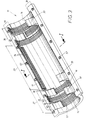
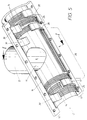
- the repair clamp shown in Fig. 1 and 2 consists of two cylinder segments 11, 12, which are intended to be used around a conduit 10 to be fixed at the desired location by welding.
- the cylinder segments 11, 12 are hereinafter referred to as "segments" become.
- both the conduit 10 and the two segments 11, 12 are made of thermally weldable material.
- the two Segments 11, 12 are, as a comparison of FIGS. 3 and 5 shows are identical in shape, but differ in that here only the upper segment 12 is provided with a pipe outlet 13. From the outset, the pipe outlet 13 has one that can be seen in FIGS. 1 and 5 Passage opening 15 with the partial cylindrical concave inner surface there 14. Because of their otherwise identical structure, it is sufficient to namely lower segment 11 to consider.
- the segment 11 has boundary edges 16, 17, on which, for fastening purposes, Connect radial edge flanges 18, 19.
- the fasteners in the present case consist of bolts 58 recognizable in FIG. 2, penetrate the bores 57 of the edge flanges 18, 19 which can be seen in FIG. 3 and screwed with nuts 59.
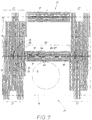
- a heating mat 20 is integrated into each of the two segments 11, 12 has a special appearance that can best be seen in FIG. 6. Also in the present case, the heating mat 20 is in both segments 11, 12 profiled the same, which is why it is sufficient in Fig. 6, the flat development of To consider heating mat of the upper segment 12 of FIG. 3.
- the outlines of the upper segment 12 are also in the plane with angled and illustrated by a dashed line.
- the Both of the aforementioned boundary edges 16, 17 of the segment 12 are highlighted.
- a special feature of the heating mat 20 is that it runs along has its two boundary edges 16, 17 different outline profiles, whose outlines 26, 27 are highlighted in FIG. 6 by dashed lines are.
- These contour lines 26, 27 are complementary to one another in the present case designed.
- This structured Outline profile has an effect on the partially cylindrical part shown in FIG.
- This cross-section 33 results not only from the continuation of the concave Cylindricity of the inner surface 14, but also in that the back 34 of the strip 36 or tab 30 is convexly curved, although with a flatter arc of curvature compared to the concave inner surface 14.
- the strip 36 or the tab 30 has one for free End 31 of the tab tapering cross-section, the present Case is wedge-shaped.
- the strip 36 or the tab 30 has a greater cross-sectional thickness 35 than in the head region 31, where the chisel tip is located here.
- FIG. 6 shows the outline profile of the mat 20 of a segment 11 or 12 can be divided into three sections 21 to 23 along the two Outline profile lines 26, 27 are profiled differently.
- the above-mentioned third section of the heating mat 20 is one of FIG. 6 recognizable heating strip 23, which is essentially axially parallel in the heating mat 20 extends and between the two heating jackets 21, 22 is arranged.
- This heating strip 23 takes place on the heating jacket 22 already has a rag 24 in front and can therefore be used with this, as in Fig. 6 illustrates to summarize the above-mentioned wide tab 28. 6
- one half of the strip 44 comes above the segment boundary edge 17 to lie, and is therefore, together with the adjacent tab 24 of the second heating jacket 22 in the integrated concave inner surface of the curved strip 36 already described. This is illustrated in Figure 3.
- the other half of the strip 45 comes below the boundary edge 17 on the concave inner surface 14 of the segment 11 or 12 to lie.
- This softened material 50 could be due to the contact gap 39 of the pressure prevailing between the two segments 11, 12 get outside. In some cases, this is even desirable because of this way by flowing out the material at a defined Make an indicator of good weld execution is achieved. In other cases, however, this is not what is desired by the invention can also be easily realized. For this it is only necessary the cross-sectional thickness 35 shown in FIG. 1 in the foot region 32 to form the bar 36 there or an analog tab 30 somewhat larger, than the thickness 51 of this material softening zone indicated in FIG. 2 50 corresponds to the wedge shape of the strip 36 or tab 30.
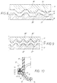
- FIG. 8 and 9 show a schematic representation of alternative relationships for outline profiles of the heating mats on the two also dash-dotted there indicated segments 11, 12, namely in a comparable with FIG. 7 Presentation.
- the position of the two heating mats 20 ', 20 " is highlighted by an opposite hatching and shows only the mutually complementary outline profile lines 26 ', 27' and 26 “, 27” on both sides of the segment boundary edges, which are also drawn in fragments there 16 ', 17' or 16 ", 17".
- Fig. 8 instead of above-described rectangular step profile a trapezoidal or toothed profile 26 ', 27' used. 9, on the other hand, have the outline profiles 26 ", 27" a waveform.
- These outline profiles can be a suitable winding profile of one comprising the electrical conductor Strands 60 easily achieve what will be described in more detail becomes.
- the pipe outlet has 13 from the outset an opening into the concave inner surface 14 Passage opening 15.
- the melt can then easily determine by a pressure test whether the welded connection is actually flawless. To do this, it is only necessary to connect to the pipe outlet 13 to create a pressure source and a pressure measuring device.
- the conduit 10 is not yet drilled at the attachment point of the clamp 11, 12 and is under any media pressure. Only when the pressure test is satisfactory, the conduit 10 is drilled, which is also through this pipe outlet 13 or via one on the opposite Segment 11 provided analog pipe outlet can be done. It arises then, as shown in FIG. 2, a borehole in the interior of the pipe outlet 13 77 in the conduit 10, which creates a media flow in the pipe outlet 13 becomes.
- FIG. 10 shows a cross-sectional representation analogous to FIG. 2 alternative embodiment of a heating strip 23 'analogous to FIG. 6 Heating mat 20 receiving segment 11 '.
- the elements shown there 11 ', 12' one of which can also carry the pipe outlet 13 ' on the flange inner surface 68 of the edge flange 18 'a vertically projecting Longitudinal rib 52 while on the opposite flange inner surface 59 of the edge flange 19 'is a longitudinal groove 53, which with respect Shape and size is complementary to the shape of the longitudinal rib 52.
- heating jackets 21, 22, which are also provided in this case, So in the end areas of the segments 11 'and 12', there are of course again the above-described, form-fitting interlocking tabs 30 and pockets 40. These heating jackets create welding zones, which also enclose the tubular surface 54 there on all sides.
- the conductor 61 used in the heating mat 20 has a special shape and represents only one component of one illustrated in FIGS. 11 to 14 combined heating strand 60. That of electrically conductive material existing wire of the conductor 61 is meandering 63 deformed. This meandering shape 63 comes about in that passes the wire through two meshing gears, their tooth shape the arches of the meander 63 created. The stretched pieces of wire 64 arise simply because at these points of the automatic Feeding the wire 61 the aforementioned two gears as far from each other be lifted off that their teeth no longer interlock to grab.
- the meander 63 is a flat wavy line. As Fig.
- the meander 63 now becomes, as in a large magnification from FIG is seen in a flat band 62 made of thermally weldable material integrated, which is now the second component of the aforementioned heating system 60 forms.
- this flat strip 62 has the cross section of a flat rectangle, the bandwidth 65 only insignificant larger than the meandering width 67 of the wire which can be seen from FIG. 11 is trained.
- the strip thickness 66 is also only slightly larger than the wire diameter 71 recognizable from FIG. 13.
- FIG. 14 shows a longitudinal section through the wall of an injection molding tool 76, in which a segment 11 or 12 is to be produced.
- 12 lies in the tool 76 a convex shape inner surface 77 with grooves 70 in which the Heating element 60, pressed in before the injection of the segment material becomes.
- Separators 61 can be provided between the grooves 70 also taper so sharply that adjacent ones already inserted in FIG. 14 Windings 73 of the heating element 60 can touch.
- the turns 73 of the heating strand 60 laid in the mold inner surface 78 are in the Grooves 70 fixed.
- FIG. 6 A possible course of the turns 63 of the heating element 60 is shown in FIG. 6 shown.
- the turns 73 consist of parallel ones Legs 74 and intermediate turning points 75.
- the turns of the heating section 60 are opposed in the heating jackets 21, 22 positioned to those in the intermediate heating strip 23.
- Fig. 5 is the heating section 60, for the sake of simple illustration, in the round profile drawn and shown only its parallel leg 74. You have to at the ends of the parallel leg 74 visible in FIG 6 turning points 75 recognizable in FIG.
- the parallel legs 74 of the strand run 60 in the area of the heating jackets 21, 22 in the cylinder circumferential direction, but in the area of the heating strip 23 in the cylinder axis direction of the segment 11.
- the turning points 75 then come, which can only be seen from FIG. 6 is to lie on the dashed outline profile lines 26, 27.
- Such laying of the electrical conductor 61 in a heating line 60 in the form of flat turns 73 lying next to one another is for the welding process particularly effectively.
- the application of such a heating system 60 is therefore not only on segments 11, 12 of the above Clamp limited. You could also use other welding fittings in this Equip way with electrical conductors, e.g. B. so-called welding sockets, with which pipes joined together in a butt joint are media-tight with one another can connect.
- Another application of such heating strands 60 results on saddle surfaces of tapping fittings or valve tapping fittings, which in an analogous manner on line pipes 10 Welding to be attached.
- the manufacture and application of the Schustrangs 60 thus has an independent inventive meaning to.
Landscapes
- Engineering & Computer Science (AREA)
- Mechanical Engineering (AREA)
- General Engineering & Computer Science (AREA)
- Lining Or Joining Of Plastics Or The Like (AREA)
- Branch Pipes, Bends, And The Like (AREA)
- Clamps And Clips (AREA)
- Rigid Pipes And Flexible Pipes (AREA)
- Thermal Insulation (AREA)
- Duct Arrangements (AREA)
- Shaping Of Tube Ends By Bending Or Straightening (AREA)
- Heat Treatment Of Articles (AREA)
- General Induction Heating (AREA)
- Pipe Accessories (AREA)
- Resistance Heating (AREA)
- Protection Of Pipes Against Damage, Friction, And Corrosion (AREA)
- Laminated Bodies (AREA)
Claims (13)
- Collier ou bride en matériau soudable thermiquement, pour un tube de canalisation (10) constitué également en un matériau soudable, tel qu'un collier ou bride de réparation,caractérisé en ce queconstitué d'au moins deux segments (11, 12) entourant en service le tube de canalisation (10), segments dont au moins l'un présente le cas échéant un départ tubulaire (13),avec des arêtes de délimitation (16, 17) tournées l'une vers l'autre en service, réalisées sur le segment (11, 12) et susceptibles d'être fixées l'une à l'autre sous pression,avec des prolongements incurvés et en forme de coin faisant saillie des arêtes de délimitation (16, 17) sur un segment et qui, en service, sont placés dans une partie en gousset réalisée entre la face intérieure du segment voisin et le tube de canalisation (10),et avec des jaquettes chauffantes (20) constituées de conducteurs (11) susceptibles d'être chauffés électriquement, enroulés, intégrés à demeure sur les faces intérieures (14) des segments (11, 12),sur chacune des deux arêtes de délimitation (16, 17) de chaque segment (11, 12), les prolongements et les éléments en gousset sont disposés les uns les autres en alternance et précisément en complémentarité vis-à-vis de ceux du segment (12, 11) chaque fois voisin et constituent une denture, formée à partir des pattes (30) ou des barrettes (36) dépassant par endroit de l'arête de délimitation (16, 17), d'une part, etet d'autre part, à partir de poches (40, 46) en position intermédiaire, qui descendent en dessous de l'arête de délimitation (16, 17) et, en service, servent à recevoir les pattes (30) ou les barrettes (36),en ce que les matelas chauffant (20) ont un profil de contour étagé, conforme à celui de la denture, constitué de pattes (24. 26) en saillie dans la zone des pattes (30) ou des barrettes (36) de segments, et de vides intermédiaires (29. 25) ménagés dans la zone des poches (40, 46).
- Collier ou bride selon la revendication 1, caractérisé en ce que la denture réalisée sur les arêtes de délimitation (16, 17) du segment (11, 12) articule le matelas chauffant (20) en trois tronçons axiaux (21, 22, 28) différents,précisément deux tronçons d'extrémité (21, 22) qui, en service, constituent une manchette chauffante fermée, à forme annulaire. placée autour du tube de canalisation (10), à l'endroit où les conducteurs (61) enroulés s'étendent en forme d'anneaux partiels depuis le fond de poche et/ou l'extrémité de patte sur une arête de délimitation (16) jusqu'à l'extrémité de patte et/ou l'extrémité de fond de poche, sur l'arête de délimitation (17) opposée,et un ou plusieurs tronçons intermédiaires (28) décalés et qui, dans la zone d'une arête de délimitation (17) du segment (11, 12), constituent chacun une barrette chauffante (23) et s'étendent au moins partiellement (44) dans la barrette (36) en saillie,mais en laissant sans conducteur la face intérieure résiduelle (47) limitrophe du segment (11, 12), à l'emplacement où les conducteurs (61) enroulés s'étendent précisément entre les deux tronçons d'extrémité (21, 22).
- Collier ou bride selon la revendication 1 ou 2, caractérisé en ce que l'épaisseur de section transversale (35) de la patte (30) ou de la barrette (36) incurvée en forme de coin, dans la zone de pied (32) tournée vers l'arête de délimitation (16, 17) du segment (11, 12), est réalisée plus grande que l'épaisseur (51) de la zone d'amollissement de matériau, qui résulte du chauffage du conducteur électrique (61) dans la patte (30) et/ou dans la barrette (36).
- Collier ou bride selon l'une ou plusieurs des revendications 1 à 3, caractérisé en ce que le conducteur électrique (61) est disposé à une distance axiale exempte de chauffage par rapport à des faces latérales de la patte (30) et/ou de la barrette (36), cette distance étant supérieure à l'épaisseur (51) de la zone d'amollissement de matériau (50) lors du chauffage.
- Collier ou bride selon l'une ou plusieurs des revendications 1 à 4, caractérisé en ce que le matelas chauffant (20) d'un segment (11, 12) est réalisé avec son profil de contour (26, 27) articulé, à partir des enroulements (73) d'un conducteur électrique (61) continu unique.
- Collier ou bride selon la revendication 5, caractérisé en ce que les conducteurs (61) des matelas de chauffage (20) de tous les segments (11, 12) sont branchés ensemble électriquement en série et sont raccordés à un robot de soudage, dans le but d'obtenir un chauffage commun régulier.
- Collier ou bride selon l'une ou plusieurs des revendications 1 à 6. caractérisé en ce que les enroulements (73) du conducteur (61) sont constitués de branches (74) parallèles et de points de rebroussement (75) intermédiaires,en ce que les branches (74) se développent dans la zone des deux tronçons d'extrémité (21, 22) en créant un anneau partiel de la manchette chauffante fermée, du matelas chauffant (20), dans la direction périphérique du cylindre,et s'étendent dans la zone de la bande chauffante (23) se trouvant dans le tronçon intermédiaire (28) du matelas chauffant (20), dans la direction axiale du cylindre du segment (11, 12),tandis que les points de rebroussement de direction (75) sont situés sur la ligne de profil de contour (26, 27) étagée des pattes (24, 28) ou des vides (25, 29) de la jaquette chauffante (20).
- Collier ou bride selon l'une ou plusieurs des revendications 1 à 7, caractérisé en ce que le conducteur électrique (61) est constitué d'un fil métallique s'étendant sous la forme d'une ligne ondulée, en forme de méandre (63), et en ce que le fil métallique en méandre (63) est posé en formant des enroulements (73) qui constituent la jaquette chauffante (20).
- Collier ou bride selon la revendication 8, caractérisé en ce que le fil métallique en méandre (63) présente, sur ses deux extrémités sortant du tronçon chauffant (60), des pièces d'extrémité de fil (64), continuant à s'étendre de façon étirée et qui sont reliés à des contacts électriques appartenant au segment (11, 12).
- Collier ou bride selon l'une ou plusieurs des revendications 1 à 9, caractérisé en ce que les étagements ménagés dans le profil de contour (26, 27) du matelas chauffant (20) sont réalisés à angle droit.
- Collier ou bride selon l'une ou plusieurs des revendications 1 à 10, caractérisé en ce que les segments (11, 12) présentent. sur au moins l'une de leurs deux arêtes de délimitation (16, 17) parallèles à l'axe une bride de bordure (18, 19) radiale et en ce que, entre les brides de bordure de segments (11, 12) voisins, s'engagent des moyens de fixation (57 à 59), pour constituer le collier ou bride entourant le tube de canalisation (10) en exerçant une pression radiale.
- Collier ou bride selon l'une ou plusieurs des revendications 1 à 11, caractérisé en ce que la bride de bordure (18') du segment (11') porte sur sa face intérieure de bride une nervure longitudinale (52') dans laquelle est intégrée la barrette chauffante (23') parallèle à l'axe du matelas chauffant,et en ce que, sur la surface intérieure de bride (69) de la bride de bordure (19') opposée de ce segment (11') et/ou du segment (12') voisin. est creusée une rainure longitudinale (53) ayant une largeur et une profondeur libres complémentaire de la forme de la nervure longitudinale (52), et qui, en service, sert à recevoir la nervure longitudinale (52).
- Collier ou bride selon l'une ou plusieurs des revendications 1 à 12, caractérisé en ce que l'épaisseur de la section transversale de la patte (30) et/ou de la barrette (36) présente une taille suffisante pour que le matériau (56) amolli passe à l'extérieur.
Priority Applications (1)
| Application Number | Priority Date | Filing Date | Title |
|---|---|---|---|
| SI9730004T SI0891509T1 (en) | 1996-06-12 | 1997-04-24 | Weldable clamp for a pipe made of a thermally weldable material |
Applications Claiming Priority (3)
| Application Number | Priority Date | Filing Date | Title |
|---|---|---|---|
| DE19623353A DE19623353C1 (de) | 1996-06-12 | 1996-06-12 | Schelle für ein aus thermisch schweißfähigem Material bestehendes Leitungsrohr |
| DE19623353 | 1996-06-12 | ||
| PCT/EP1997/002080 WO1997047912A1 (fr) | 1996-06-12 | 1997-04-24 | Bride soudable pour tube de conduite realise dans un materiau thermosoudable |
Publications (2)
| Publication Number | Publication Date |
|---|---|
| EP0891509A1 EP0891509A1 (fr) | 1999-01-20 |
| EP0891509B1 true EP0891509B1 (fr) | 1999-09-22 |
Family
ID=7796684
Family Applications (1)
| Application Number | Title | Priority Date | Filing Date |
|---|---|---|---|
| EP97920745A Expired - Lifetime EP0891509B1 (fr) | 1996-06-12 | 1997-04-24 | Bride soudable pour tube de conduite realise dans un materiau thermosoudable |
Country Status (13)
| Country | Link |
|---|---|
| EP (1) | EP0891509B1 (fr) |
| JP (1) | JP2000516688A (fr) |
| AT (1) | ATE184972T1 (fr) |
| BG (1) | BG63132B1 (fr) |
| DE (3) | DE19623353C1 (fr) |
| ES (1) | ES2136472T3 (fr) |
| GR (1) | GR3031454T3 (fr) |
| HU (1) | HU221893B1 (fr) |
| NO (1) | NO314600B1 (fr) |
| PL (1) | PL330538A1 (fr) |
| SK (1) | SK282405B6 (fr) |
| WO (1) | WO1997047912A1 (fr) |
| YU (1) | YU49320B (fr) |
Families Citing this family (5)
| Publication number | Priority date | Publication date | Assignee | Title |
|---|---|---|---|---|
| DE102004020758A1 (de) * | 2004-04-27 | 2005-11-17 | Gwc Gas-Water-Valves-Components Gmbh | Schelle aus thermisch schweißfähigem Material |
| DE102004023338A1 (de) * | 2004-05-12 | 2005-12-15 | Gwc Gas-Water-Valves-Components Gmbh | Heizvorrichtung zum Verschweißen von mindestens zwei aus einem Kunststoffmaterial bestehenden Gegenständen |
| JP2012219934A (ja) * | 2011-04-11 | 2012-11-12 | Cosmo Koki Co Ltd | 管継手及び管継手の取付方法 |
| JP5773717B2 (ja) * | 2011-04-11 | 2015-09-02 | コスモ工機株式会社 | 管継手 |
| CN110315763B (zh) * | 2019-07-03 | 2022-03-15 | 天津市津能管业有限公司 | 一种自动热熔焊接机及焊接方法 |
Family Cites Families (6)
| Publication number | Priority date | Publication date | Assignee | Title |
|---|---|---|---|---|
| US2690193A (en) * | 1948-01-26 | 1954-09-28 | Telford L Smith | Pipe clamp |
| ES500110A0 (es) * | 1980-03-10 | 1982-05-01 | Fischer Ag Georg | Dispositivo de empalme por soldadura de dos tubos alineados de material sintetico |
| CH652473A5 (de) * | 1981-10-02 | 1985-11-15 | Fischer Ag Georg | Schweissverbindung fuer kunststoffrohre. |
| CH655374A5 (de) * | 1982-04-29 | 1986-04-15 | Fischer Ag Georg | Anschluss-formstueck. |
| CH671819A5 (fr) * | 1986-07-31 | 1989-09-29 | Meier Schenk Ag | |
| DE29504367U1 (de) * | 1995-03-19 | 1995-08-17 | Jeschke, Immanuel, 31157 Sarstedt | Vorrichtung zum Anbohren von Kunststoffrohren von Versorgungsleitungen |
-
1996
- 1996-06-12 DE DE19623353A patent/DE19623353C1/de not_active Expired - Fee Related
-
1997
- 1997-04-24 PL PL97330538A patent/PL330538A1/xx unknown
- 1997-04-24 YU YU55598A patent/YU49320B/sh unknown
- 1997-04-24 SK SK1570-98A patent/SK282405B6/sk unknown
- 1997-04-24 WO PCT/EP1997/002080 patent/WO1997047912A1/fr not_active Ceased
- 1997-04-24 JP JP10501098A patent/JP2000516688A/ja active Pending
- 1997-04-24 AT AT97920745T patent/ATE184972T1/de active
- 1997-04-24 HU HU9903170A patent/HU221893B1/hu not_active IP Right Cessation
- 1997-04-24 ES ES97920745T patent/ES2136472T3/es not_active Expired - Lifetime
- 1997-04-24 DE DE59700478T patent/DE59700478D1/de not_active Expired - Lifetime
- 1997-04-24 EP EP97920745A patent/EP0891509B1/fr not_active Expired - Lifetime
- 1997-05-09 DE DE59700480T patent/DE59700480D1/de not_active Expired - Lifetime
-
1998
- 1998-12-04 BG BG102990A patent/BG63132B1/bg unknown
- 1998-12-07 NO NO19985717A patent/NO314600B1/no unknown
-
1999
- 1999-10-07 GR GR990402543T patent/GR3031454T3/el unknown
Also Published As
| Publication number | Publication date |
|---|---|
| DE19623353C1 (de) | 1998-01-29 |
| EP0891509A1 (fr) | 1999-01-20 |
| DE59700480D1 (de) | 1999-10-28 |
| GR3031454T3 (en) | 2000-01-31 |
| PL330538A1 (en) | 1999-05-24 |
| HUP9903170A2 (hu) | 2000-02-28 |
| HU221893B1 (hu) | 2003-02-28 |
| DE59700478D1 (de) | 1999-10-28 |
| BG63132B1 (bg) | 2001-04-30 |
| SK157098A3 (en) | 1999-03-12 |
| NO314600B1 (no) | 2003-04-14 |
| JP2000516688A (ja) | 2000-12-12 |
| YU55598A (sh) | 1999-09-27 |
| NO985717D0 (no) | 1998-12-07 |
| ATE184972T1 (de) | 1999-10-15 |
| BG102990A (en) | 1999-07-30 |
| YU49320B (sh) | 2005-06-10 |
| NO985717L (no) | 1998-12-07 |
| WO1997047912A1 (fr) | 1997-12-18 |
| SK282405B6 (sk) | 2002-01-07 |
| HUP9903170A3 (en) | 2000-03-28 |
| ES2136472T3 (es) | 1999-11-16 |
Similar Documents
| Publication | Publication Date | Title |
|---|---|---|
| DE3103305C2 (de) | Elektrisch schweißbare Muffe zum Verbinden von Leitungselementen | |
| DE69703882T2 (de) | Verfahren und vorrichtung zum verbinden von thermoplastichen gegenständen | |
| DE2728971C3 (de) | Einsatz für ein Wärmetauscherrohr | |
| DE8318686U1 (de) | Schweissformstueck zur verbindung vorgefertigter waermeisolierter rohrleitungen | |
| DE2514827A1 (de) | Anbohrformstueck aus schweissbarem kunststoff | |
| EP0619176A2 (fr) | Procédé pour le soudage de tubes en matière plastique | |
| DE3445493A1 (de) | Flexibler schlauch mit rechteckigem querschnitt, insbesondere energieleitungstraeger | |
| EP1027553A1 (fr) | Bride de fixation soudable pour conduite constituee d'un materiau pouvant etre soude thermiquement | |
| DE3615879A1 (de) | Vorrichtung zum thermischen verbinden von foerdergurtenden | |
| DE3042073C2 (de) | Tube | |
| EP1046007B1 (fr) | Bride en materiau thermosoudable pour tuyaux de conduite | |
| DE2845271A1 (de) | Schweissbacke fuer verpackungsmaschinen | |
| DE19623353C1 (de) | Schelle für ein aus thermisch schweißfähigem Material bestehendes Leitungsrohr | |
| CH661475A5 (de) | Anordnung zum verschweissen von formteilen aus thermoplastischem kunststoff. | |
| DE69632269T2 (de) | Verbindungsleitung für einen zaun und zaun | |
| DE19543083C2 (de) | Verfahren zum Verbinden aus schweißfähigem Kunststoff bestehender Wellrohre | |
| DE29616864U1 (de) | Anschweißbare Schelle für ein aus thermisch schweißfähigem Material bestehendes Leitungsrohr | |
| EP0239741A1 (fr) | Tuyau double composé de deux tuyaux de protection liés entre eux en une seule pièce par une nervure | |
| DE69304746T2 (de) | Verfahren zur Herstellung eines katalytischen Konverters zur Abgasreinigung | |
| DE19526795C1 (de) | Verbundprofil und Verfahren zur Herstellung desselben | |
| DE202014003776U1 (de) | Kunststoffrohr | |
| EP0891510A1 (fr) | Procede de production d'un element de robinetterie pour tubes, en materiau thermosoudable | |
| DE2604508C3 (de) | Abschlußmanschette für ein Schutzrohr | |
| DE69611998T2 (de) | Stange eines gepäckträgers und verfahren zur herstellung | |
| DE112006000537B4 (de) | Auspuffkrümmer für Auspuffgase |
Legal Events
| Date | Code | Title | Description |
|---|---|---|---|
| PUAI | Public reference made under article 153(3) epc to a published international application that has entered the european phase |
Free format text: ORIGINAL CODE: 0009012 |
|
| 17P | Request for examination filed |
Effective date: 19981116 |
|
| AK | Designated contracting states |
Kind code of ref document: A1 Designated state(s): AT BE CH DE DK ES FI FR GB GR IE IT LI NL PT SE |
|
| AX | Request for extension of the european patent |
Free format text: SI PAYMENT 981015 |
|
| GRAG | Despatch of communication of intention to grant |
Free format text: ORIGINAL CODE: EPIDOS AGRA |
|
| 17Q | First examination report despatched |
Effective date: 19990201 |
|
| GRAG | Despatch of communication of intention to grant |
Free format text: ORIGINAL CODE: EPIDOS AGRA |
|
| GRAH | Despatch of communication of intention to grant a patent |
Free format text: ORIGINAL CODE: EPIDOS IGRA |
|
| GRAH | Despatch of communication of intention to grant a patent |
Free format text: ORIGINAL CODE: EPIDOS IGRA |
|
| GRAA | (expected) grant |
Free format text: ORIGINAL CODE: 0009210 |
|
| AK | Designated contracting states |
Kind code of ref document: B1 Designated state(s): AT BE CH DE DK ES FI FR GB GR IE IT LI NL PT SE |
|
| AX | Request for extension of the european patent |
Free format text: SI PAYMENT 19981015 |
|
| REF | Corresponds to: |
Ref document number: 184972 Country of ref document: AT Date of ref document: 19991015 Kind code of ref document: T |
|
| REG | Reference to a national code |
Ref country code: CH Ref legal event code: NV Representative=s name: ISLER & PEDRAZZINI AG Ref country code: CH Ref legal event code: EP |
|
| ITF | It: translation for a ep patent filed | ||
| ET | Fr: translation filed | ||
| REF | Corresponds to: |
Ref document number: 59700478 Country of ref document: DE Date of ref document: 19991028 |
|
| REG | Reference to a national code |
Ref country code: ES Ref legal event code: FG2A Ref document number: 2136472 Country of ref document: ES Kind code of ref document: T3 |
|
| GBT | Gb: translation of ep patent filed (gb section 77(6)(a)/1977) |
Effective date: 19991028 |
|
| REG | Reference to a national code |
Ref country code: IE Ref legal event code: FG4D Free format text: GERMAN |
|
| REG | Reference to a national code |
Ref country code: DK Ref legal event code: T3 |
|
| REG | Reference to a national code |
Ref country code: PT Ref legal event code: SC4A Free format text: AVAILABILITY OF NATIONAL TRANSLATION Effective date: 19990923 |
|
| PGFP | Annual fee paid to national office [announced via postgrant information from national office to epo] |
Ref country code: PT Payment date: 20000413 Year of fee payment: 4 |
|
| PGFP | Annual fee paid to national office [announced via postgrant information from national office to epo] |
Ref country code: GR Payment date: 20000426 Year of fee payment: 4 |
|
| PLBE | No opposition filed within time limit |
Free format text: ORIGINAL CODE: 0009261 |
|
| STAA | Information on the status of an ep patent application or granted ep patent |
Free format text: STATUS: NO OPPOSITION FILED WITHIN TIME LIMIT |
|
| 26N | No opposition filed | ||
| PG25 | Lapsed in a contracting state [announced via postgrant information from national office to epo] |
Ref country code: PT Free format text: LAPSE BECAUSE OF NON-PAYMENT OF DUE FEES Effective date: 20011031 Ref country code: GR Free format text: LAPSE BECAUSE OF NON-PAYMENT OF DUE FEES Effective date: 20011031 |
|
| REG | Reference to a national code |
Ref country code: GB Ref legal event code: IF02 |
|
| REG | Reference to a national code |
Ref country code: PT Ref legal event code: MM4A Free format text: LAPSE DUE TO NON-PAYMENT OF FEES Effective date: 20011031 |
|
| PGFP | Annual fee paid to national office [announced via postgrant information from national office to epo] |
Ref country code: IE Payment date: 20050221 Year of fee payment: 9 |
|
| PGFP | Annual fee paid to national office [announced via postgrant information from national office to epo] |
Ref country code: FI Payment date: 20050331 Year of fee payment: 9 |
|
| PGFP | Annual fee paid to national office [announced via postgrant information from national office to epo] |
Ref country code: SE Payment date: 20050406 Year of fee payment: 9 |
|
| PG25 | Lapsed in a contracting state [announced via postgrant information from national office to epo] |
Ref country code: IE Free format text: LAPSE BECAUSE OF NON-PAYMENT OF DUE FEES Effective date: 20060424 Ref country code: FI Free format text: LAPSE BECAUSE OF NON-PAYMENT OF DUE FEES Effective date: 20060424 |
|
| PG25 | Lapsed in a contracting state [announced via postgrant information from national office to epo] |
Ref country code: SE Free format text: LAPSE BECAUSE OF NON-PAYMENT OF DUE FEES Effective date: 20060425 |
|
| EUG | Se: european patent has lapsed | ||
| REG | Reference to a national code |
Ref country code: IE Ref legal event code: MM4A |
|
| REG | Reference to a national code |
Ref country code: CH Ref legal event code: PCAR Free format text: ISLER & PEDRAZZINI AG;POSTFACH 1772;8027 ZUERICH (CH) |
|
| PGFP | Annual fee paid to national office [announced via postgrant information from national office to epo] |
Ref country code: ES Payment date: 20110408 Year of fee payment: 15 Ref country code: FR Payment date: 20110503 Year of fee payment: 15 Ref country code: CH Payment date: 20110502 Year of fee payment: 15 Ref country code: DE Payment date: 20110228 Year of fee payment: 15 |
|
| PGFP | Annual fee paid to national office [announced via postgrant information from national office to epo] |
Ref country code: NL Payment date: 20110502 Year of fee payment: 15 Ref country code: GB Payment date: 20110421 Year of fee payment: 15 Ref country code: DK Payment date: 20110426 Year of fee payment: 15 Ref country code: AT Payment date: 20110419 Year of fee payment: 15 Ref country code: BE Payment date: 20110426 Year of fee payment: 15 |
|
| PGFP | Annual fee paid to national office [announced via postgrant information from national office to epo] |
Ref country code: IT Payment date: 20110421 Year of fee payment: 15 |
|
| BERE | Be: lapsed |
Owner name: *MANIBS SPEZIALARMATUREN G.M.B.H. & CO. K.G. Effective date: 20120430 |
|
| REG | Reference to a national code |
Ref country code: NL Ref legal event code: V1 Effective date: 20121101 |
|
| REG | Reference to a national code |
Ref country code: DK Ref legal event code: EBP |
|
| REG | Reference to a national code |
Ref country code: CH Ref legal event code: PL |
|
| REG | Reference to a national code |
Ref country code: AT Ref legal event code: MM01 Ref document number: 184972 Country of ref document: AT Kind code of ref document: T Effective date: 20120424 |
|
| GBPC | Gb: european patent ceased through non-payment of renewal fee |
Effective date: 20120424 |
|
| REG | Reference to a national code |
Ref country code: FR Ref legal event code: ST Effective date: 20121228 |
|
| PG25 | Lapsed in a contracting state [announced via postgrant information from national office to epo] |
Ref country code: AT Free format text: LAPSE BECAUSE OF NON-PAYMENT OF DUE FEES Effective date: 20120424 Ref country code: BE Free format text: LAPSE BECAUSE OF NON-PAYMENT OF DUE FEES Effective date: 20120430 Ref country code: LI Free format text: LAPSE BECAUSE OF NON-PAYMENT OF DUE FEES Effective date: 20120430 Ref country code: CH Free format text: LAPSE BECAUSE OF NON-PAYMENT OF DUE FEES Effective date: 20120430 Ref country code: GB Free format text: LAPSE BECAUSE OF NON-PAYMENT OF DUE FEES Effective date: 20120424 |
|
| REG | Reference to a national code |
Ref country code: DE Ref legal event code: R119 Ref document number: 59700478 Country of ref document: DE Effective date: 20121101 |
|
| PG25 | Lapsed in a contracting state [announced via postgrant information from national office to epo] |
Ref country code: FR Free format text: LAPSE BECAUSE OF NON-PAYMENT OF DUE FEES Effective date: 20120430 Ref country code: IT Free format text: LAPSE BECAUSE OF NON-PAYMENT OF DUE FEES Effective date: 20120424 |
|
| PG25 | Lapsed in a contracting state [announced via postgrant information from national office to epo] |
Ref country code: NL Free format text: LAPSE BECAUSE OF NON-PAYMENT OF DUE FEES Effective date: 20121101 |
|
| REG | Reference to a national code |
Ref country code: ES Ref legal event code: FD2A Effective date: 20130715 |
|
| PG25 | Lapsed in a contracting state [announced via postgrant information from national office to epo] |
Ref country code: ES Free format text: LAPSE BECAUSE OF NON-PAYMENT OF DUE FEES Effective date: 20120425 |
|
| PG25 | Lapsed in a contracting state [announced via postgrant information from national office to epo] |
Ref country code: DK Free format text: LAPSE BECAUSE OF NON-PAYMENT OF DUE FEES Effective date: 20120430 |
|
| PG25 | Lapsed in a contracting state [announced via postgrant information from national office to epo] |
Ref country code: DE Free format text: LAPSE BECAUSE OF NON-PAYMENT OF DUE FEES Effective date: 20121101 |