EP0891723A2 - Bouton-pression et son procédé de fixation - Google Patents
Bouton-pression et son procédé de fixation Download PDFInfo
- Publication number
- EP0891723A2 EP0891723A2 EP98113407A EP98113407A EP0891723A2 EP 0891723 A2 EP0891723 A2 EP 0891723A2 EP 98113407 A EP98113407 A EP 98113407A EP 98113407 A EP98113407 A EP 98113407A EP 0891723 A2 EP0891723 A2 EP 0891723A2
- Authority
- EP
- European Patent Office
- Prior art keywords
- male
- snap
- female
- resilient
- shank
- Prior art date
- Legal status (The legal status is an assumption and is not a legal conclusion. Google has not performed a legal analysis and makes no representation as to the accuracy of the status listed.)
- Withdrawn
Links
Images





Classifications
-
- A—HUMAN NECESSITIES
- A44—HABERDASHERY; JEWELLERY
- A44B—BUTTONS, PINS, BUCKLES, SLIDE FASTENERS, OR THE LIKE
- A44B17/00—Press-button or snap fasteners
- A44B17/0029—Press-button fasteners made of plastics
- A44B17/0035—Their fastening
-
- Y—GENERAL TAGGING OF NEW TECHNOLOGICAL DEVELOPMENTS; GENERAL TAGGING OF CROSS-SECTIONAL TECHNOLOGIES SPANNING OVER SEVERAL SECTIONS OF THE IPC; TECHNICAL SUBJECTS COVERED BY FORMER USPC CROSS-REFERENCE ART COLLECTIONS [XRACs] AND DIGESTS
- Y10—TECHNICAL SUBJECTS COVERED BY FORMER USPC
- Y10T—TECHNICAL SUBJECTS COVERED BY FORMER US CLASSIFICATION
- Y10T24/00—Buckles, buttons, clasps, etc.
- Y10T24/34—Combined diverse multipart fasteners
- Y10T24/3401—Buckle
- Y10T24/3423—Buckle and separable fastening means for attached fastener
- Y10T24/3424—Snap fastener
-
- Y—GENERAL TAGGING OF NEW TECHNOLOGICAL DEVELOPMENTS; GENERAL TAGGING OF CROSS-SECTIONAL TECHNOLOGIES SPANNING OVER SEVERAL SECTIONS OF THE IPC; TECHNICAL SUBJECTS COVERED BY FORMER USPC CROSS-REFERENCE ART COLLECTIONS [XRACs] AND DIGESTS
- Y10—TECHNICAL SUBJECTS COVERED BY FORMER USPC
- Y10T—TECHNICAL SUBJECTS COVERED BY FORMER US CLASSIFICATION
- Y10T24/00—Buckles, buttons, clasps, etc.
- Y10T24/45—Separable-fastener or required component thereof [e.g., projection and cavity to complete interlock]
- Y10T24/45225—Separable-fastener or required component thereof [e.g., projection and cavity to complete interlock] including member having distinct formations and mating member selectively interlocking therewith
- Y10T24/45602—Receiving member includes either movable connection between interlocking components or variable configuration cavity
- Y10T24/45775—Receiving member includes either movable connection between interlocking components or variable configuration cavity having resiliently biased interlocking component or segment
- Y10T24/45864—Receiving member includes either movable connection between interlocking components or variable configuration cavity having resiliently biased interlocking component or segment having portion of cavity deformed during mounting
-
- Y—GENERAL TAGGING OF NEW TECHNOLOGICAL DEVELOPMENTS; GENERAL TAGGING OF CROSS-SECTIONAL TECHNOLOGIES SPANNING OVER SEVERAL SECTIONS OF THE IPC; TECHNICAL SUBJECTS COVERED BY FORMER USPC CROSS-REFERENCE ART COLLECTIONS [XRACs] AND DIGESTS
- Y10—TECHNICAL SUBJECTS COVERED BY FORMER USPC
- Y10T—TECHNICAL SUBJECTS COVERED BY FORMER US CLASSIFICATION
- Y10T24/00—Buckles, buttons, clasps, etc.
- Y10T24/45—Separable-fastener or required component thereof [e.g., projection and cavity to complete interlock]
- Y10T24/45225—Separable-fastener or required component thereof [e.g., projection and cavity to complete interlock] including member having distinct formations and mating member selectively interlocking therewith
- Y10T24/45602—Receiving member includes either movable connection between interlocking components or variable configuration cavity
- Y10T24/45775—Receiving member includes either movable connection between interlocking components or variable configuration cavity having resiliently biased interlocking component or segment
- Y10T24/45874—Receiving member includes either movable connection between interlocking components or variable configuration cavity having resiliently biased interlocking component or segment having axially extending expansion slit along side of cavity
-
- Y—GENERAL TAGGING OF NEW TECHNOLOGICAL DEVELOPMENTS; GENERAL TAGGING OF CROSS-SECTIONAL TECHNOLOGIES SPANNING OVER SEVERAL SECTIONS OF THE IPC; TECHNICAL SUBJECTS COVERED BY FORMER USPC CROSS-REFERENCE ART COLLECTIONS [XRACs] AND DIGESTS
- Y10—TECHNICAL SUBJECTS COVERED BY FORMER USPC
- Y10T—TECHNICAL SUBJECTS COVERED BY FORMER US CLASSIFICATION
- Y10T24/00—Buckles, buttons, clasps, etc.
- Y10T24/45—Separable-fastener or required component thereof [e.g., projection and cavity to complete interlock]
- Y10T24/45225—Separable-fastener or required component thereof [e.g., projection and cavity to complete interlock] including member having distinct formations and mating member selectively interlocking therewith
- Y10T24/4588—Means for mounting projection or cavity portion
- Y10T24/45885—Allows bodily movement facilitating interlock
Definitions
- the present invention relates to a snap button composed of male and female members to be used as a fastener of, for example, clothing, and a method of attaching such a snap button to a cloth with resiliency.
- each of the male and female members 102, 101 has a shank 121, 110 projecting centrally from its face plates 104, 103.
- the male member 102 and the male member 101 have a spherical head 121' and a fitting recess 112 at their respective shanks 121, 110 so that they can be engaged for by a snap action.
- a pair of washers 121, 110 each having a central hole smaller in diameter than each of the shanks 121, 110 are threaded respectively on each shank 121, 110 to clamp each of the corresponding parts of the cloth C-1 between each face plate 104, 103 and each corresponding washer 151, 150.
- Japanese Patent Laid-Open Publication No. Hei 8-173214 discloses a hook and eye fastener of synthetic resin.
- the fastener comprises male and female bodies 206, 205, a pair of packing rings 261, 260 and a pair of face plates 204, 203.
- the female body 205 as a socket is made of polyacetal resin and has an axial plug-insertion recess 212, the recess 212 having centrally in its bottom a seated packing hole 214 on the outer side, while the male body 206 as a plug has a tubular shank 228, which is to be releasably fitted in the plug-insertion recess 212 of the female body 205, and centrally in the bottom of the tubular shank 228 on the outer side a seated packing hole 214.
- the packing rings 261, 260 are made of soft urethane resin and are fixed in the respective packing holes 225, 214 of the male and female bodies 206, 205 by fitting, gluing or welding.
- Each packing ring 261, 260 has a removal-prevention flange 265, 264 to contact with each seat 271, 270 of the male and female bodies 206, 205 and central leg-insertion holes 263, 262.
- the face plates 204, 203 are made of polyacetal resin having an axial leg to be clenched. During attaching, the legs 221, 210 of each face plate 204, 203 is pierced through each of the corresponding parts of the cloth C-2 and inserted trough the respective packing ring 261, 260 and then, is clenched in the socket or plug of the corresponding bodies 206, 205. Thus attaching of the male and female bodies 206, 205 to the cloth C-2 has been completed. In use, the tubular shank 228 of the plug of the male member 202 is coupled and uncoupled with the undercut plug-insertion hole 212 of the socket of the female member 201.
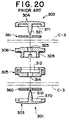
- Japanese Patent Laid-Open Publication No. Hei 8-294405 discloses an eye and hook fastener of synthetic resin, which comprises a female body 305 of a female member 301 as a socket, a male body 306 of a male member 302 as a plug, a pair of packings 360, 361 and pair of face plates 303, 304, as shown in Fig. 20 of the accompanying drawings.
- the female body 305 has a plug-insertion recess 312 on the inner side, the recess 312 having in its bottom a leg-insertion hole 314, while the male body 306 has a tubular shank 323, which is to be fitted in the plug-insertion recess 312 of the socket of the female body 305, and centrally in the bottom of the tubular shank 323 a leg-insertion hole 325.
- the face plate 303, 304 has an axial leg 310, 321 to be clenched. And each face plate 303, 304 has in its inner surface a packing recess 370, 371 for fixedly receiving each packing 360, 361 which is made of a soft urethane resin by gluing or welding.
- the axial legs 321, 310 of the face plates 304, 303 are threaded through the packings 361, 360 and then pierced through the cloth and finally inserted into the central holes 325, 314 of each of the male and female bodies 306, 305, whereupon the axial legs 321, 310 of the face plates 304, 303 are clenched by the pressure of the punch.
- each of the male and female members 302, 301 of the snap button is attached to the cloth by a single clenching operation.
- the axial shanks 121, 110 of each of the male and female face plates 104, 103 is difficult to make slender and taper enough to pierce the cloth when attaching each of the male and female members 102, 101 to the cloth C-1.
- the shanks 121, 110 is a particularly large-sized cylindrical tube so that the piercing of the shanks 121, 110 through the cloth C-1 would be laborious and time-consuming.
- the washers 151, 150 are threaded on the shanks 121, 110 and fixed only at the peripheral edge of the pierced hole of the cloth C-1, it would tend to be displaced in use, thus the cloth C-1 can not be clamped in a stable manner.
- each of the plug and socket of the male and female bodies 206, 205 has in its rear surface packing holes 225, 214, in which soft urethane resin packing rings 261, 260 are stably secured by fitting, gluing or welding.
- the clamping of the cloth C-2 relies on only the clenching of the legs 221, 210, in which case the packings 261, 260 actually perform their original waterproofing feature but would be totally useless in securing the cloth C-2. Accordingly either of the male and female members 202, 201 would tend to become loose in securing after attached to the cloth.
- each of male and female buttons secures a cloth at two locations, i.e., between a resilient plate and an axial shank of a face plate and between a snap body and the shank, and can therefore be attached to the cloth firmly and simply without any accidental removal of the face plate.
- the face plate will not be removed from the cloth even if it would happen to suffer a breakage or other damage due to fatigue as the male and female buttons are repeatedly coupled and uncoupled, thus realizing a tough, double-fixed snap button.
- a second object of the invention is to provide a snap button in which each resilient plate has such a shape that the face plate and the resilient plate can catch the cloth reliably and easily, thus achieving a firm and stable attachment.
- a third object of the invention is to provide a snap button in which each of the male and female resilient plates has an inwardly curled peripheral edge, and the peripheral flange of each of the male and female snap bodies has an outwardly bent peripheral edge, and yet the socket/plug portions of each of the male and female snap bodies has an outwardly bulging bottom for pressing a respective one of the male and female resilient plates around its central hole, and therefore the resilient plate can press the cloth against the face plate by its entire surface to secure the cloth firmly and stably, realizing a damage-proof tough snap button.
- a fourth object of the invention is to provide a snap button in which the resilient plate can be secured to the snap body reliably and firmly and can therefore be engaged with the shank in a stabilized posture and can be reinforced.
- a fifth object of the invention is to provide a snap button in which each of the male and female resilient plates has a central hole smaller in diameter than an axial shank of a respective one of the male and female face plates, and the peripheral edge of the respective central hole is in biting engagement with each shank, and therefore enables the shank of the face plate to join with the resilient plate firmly without accidental removal.
- a sixth object of the invention is to provide a snap button in which an outer surface of the respective peripheral flange of each of male and female snap bodies is located outward of the bottom of a respective one of the plug and socket portions, and each resilient plate is superposed over the outer surface of the respective peripheral flange, and yet each of the male and female snap bodies has around the respective shank-insertion hole a peripheral recess for allowing each resilient plate to deform, thereby locating the resilient plate in a stabilized posture against the snap body and facilitating resilient deformation of the resilient plate and also clamping the cloth margin without difficulty.
- a seventh object of the invention is to provide a snap button in which the peripheral edge of the central hole of each resilient plate is inwardly bent so as to bite into a respective one of the shanks and, therefore, the shank of the face plate can be threaded through the snap body reliably and simply without accidental removal.
- An eighth object of the invention is to provide a snap button in which the bottom of each of the plug and socket portions is located outward of a respective one of the peripheral flanges of the male and female snap bodies so as to clamp the cloth between the bottom and each face plate, and each resilient plate is a small-sized frustum resilient plate mounted in a respective one of the concave plug and socket portions, and yet each shank is smashed so as to engage the frustum resilient plate, and therefore the resilient plate can be engaged with the shank of the face plate simply and reliably to achieve adequate engagement by yet the small-sized resilient plate and also to save material, thus resulting in reduction of price.
- a ninth object of the invention is to provide a snap button in which each face plate is made of a material softer than that of each resilient plate and the shank of each face plate has an axial hollow portion therein. Therefore, the shank can be smashed or clenched without difficulty, so that quick and reliable attachment of the snap body to the cloth can be achieved, thus improving the attaching efficiency.
- a tenth object of the invention is to provide a snap button in which each face plate and each snap body are molded of thermoplastic resin and each resilient plate is made from a metal sheet, and therefore reliable engagement can be achieved using optimum materials for the snap body, the face plate and the resilient plate so that an ideal snap button can be realized.
- An eleventh object of the invention is to provide a method of attaching a snap button to a cloth, which enables each snap body of the snap button to be secured to the shank of each face plate firmly at certain positions using the respective resilient plate and also enables inspection intermediate between the first and second steps by the operator's eyes so that reliable checking can be performed on whether or not the cloth is surely held between the face plate and the resilient plate, thereby guaranteeing a damage-free snap button.
- a twelfth object of the invention is to provide a method of attaching a snap button to a cloth in which the snap button can be attached to the cloth simply in various forms in option by specifying the punch or punches utilizing each of the male and female face plates, the respective snap bodies and the respective resilient plates.
- a snap button for attachment to a cloth, which is composed of male and female buttons adapted to be coupled together, the male and female buttons comprising: a male face plate having a smashable shank projecting centrally from its inner surface for piercing a first part of the cloth; a male snap body having a concave plug portion, a shank-insertion hole extending axially through the plug portion, and a peripheral flange extending from a base portion of the plug portion off an inner open end thereof; a male resilient plate adapted to be pierced by the shank so as to press the first part of the cloth against the inner surface of the male face plate; a female face plate having a smashable shank projecting centrally from its inner surface for piercing a second part of the cloth; a female snap body having a concave socket portion, a shank-insertion hole extending axially through the socket portion, and a peripheral flange extending from a base
- each of the male and female resilient plates has an arcuate surface complementary to the inner surface of a respective one of the male and female face plate.
- each of the male and female resilient plates has an inwardly curled peripheral edge
- each of the male and female snap bodies having an outwardly bent peripheral edge
- each of the plug and socket portions has an outwardly bulging bottom for pressing a respective one of the male and female resilient plates around its central hole.
- an outer peripheral edge of each resilient plate is embedded in the outer peripheral edge of a respective one of the peripheral flanges of the male and female snap bodies.
- each of the male and female resilient plates has a central hole smaller in diameter than a respective one of the shanks, and a peripheral edge of the central hole is in biting engagement with each shank.
- each resilient plate is initially devoid of a central hole and is adapted to be pierced by a respective one of the shanks under pressure.
- an outer surface of each of the peripheral flanges of the male and female snap bodies is located outward of the bottom of a respective one of the plug and socket portions, each resilient plate being superposed over the outer surface of a respective one of the peripheral flanges, each of the male and female snap bodies having around a respective one of the shank-insertion holes a peripheral recess for allowing each resilient plate to deform.
- the peripheral edge of the central hole of each resilient plate is inwardly bent so as to bite into a respective one of the shanks.
- each of the plug and socket portions is located outward of a respective one of the peripheral flanges of the male and female snap bodies so as to clamp the cloth between the bottom and each face plate, and each resilient plate is a small-sized frustum resilient plate mounted in a respective one of the concave plug and socket portions, and each shank is smashed so as to engage the frustum resilient plate.
- each face plate is made of a material softer than that of each resilient plate, the shank of each face plate having an axial hollow portion therein.
- each face plate and each snap body are molded of thermoplastic resin, and each resilient plate is made from a metal sheet.
- a method of attaching to a cloth a snap button composed of male and female snap buttons, each having a face plate, a shank projecting centrally therefrom, a resilient plate and a snap body having a shank-insertion hole comprising: a first step of piercing the shank of the face plate of each of the male and female buttons through a respective one of first and second parts of the cloth, inserting the shank through a central hole, which is smaller in diameter than the shank, of the resilient plate to clamp a respective one of the first and second part of the cloth between the resilient plate and the face plate; and a second step of pressing the shank, which is inserted through the shank-insertion hole of the snap body of each of the male and female buttons to smash the shank in the snap body.
- the resilient plate in the first step, is pressed first at its outer peripheral edge and then at a peripheral edge of the central hole to bring the resilient plate into engagement with the shank of the face plate.
- each resilient plate with the peripheral edge of its central hole resiliently deformable is superposed over the inner surface of each of the male and female snap bodies, and pressed against each snap body, thereby engaging each shank of each face plate.
- each snap body and a respect one of the first and second part of the cloth are threaded on each shank of the face plate, and a small-sized resilient plate is then threaded on each shank and is pressed against each snap body, thereby engaging each shank of each face plate.
- the terms “outwardly”, “inwardly”, “outer” and “inner” are regarded as “axially outwardly”, “axially inwardly”, “axially outer” and “axially inner”, respectively, with respect to the imaginary plane in which male and female buttons are to be coupled with each other.
- the terms “outer peripheral” and “inner peripheral” are regarded as “radially outer peripheral” and “radially inner peripheral”, respectively, with respect to the center of either the male or female button as in usage.
- the same reference numbers designate similar parts or elements throughout the different views of several embodiments.
- Figs. 1 to 5 show a snap button according to a first embodiment of the invention.
- the snap button is composed of male and female buttons 1, 2.
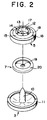
- Each of the male and female buttons 1, 2, as respectively shown in Figs. 2 and 3, has a three-member structure composed of face plates 3, 4, snap bodies 5, 6, and resilient plates 7, 8.
- Each of the face plates 3, 4 and the snap bodies 5, 6 is molded in a unitary form by injection or extrusion molding using thermoplastic resin, such as polyacetal, polyamide, polypropylene or polybutyleneterephtalate, while the resilient plates 7, 8 are preferably made from a metal sheet but may be molded of above-described thermoplastic resin.
- the face plate 3 of the female button 1 (hereinafter also called simply the female face plate) is in the form of an outwardly slightly convex disk having centrally on its inner surface a tapering axial shank 10, which is adapted to be smashed or clenched as described below.
- the female face plate 3 further has an inwardly bent outer peripheral edge 11.
- the outer surface of the female face plate 3 may serve as an ornament selectively bearing any optional combination of various designs, colors and/or shapes.
- the snap body 5 of the female button 1 (hereinafter also called simply the female snap body) has a concave socket portion 12 at its center, the bottom 13 of which has a central shank-insertion hole 14.
- the snap body 5 further has a peripheral flange 15 extending radially outwardly from a periphery of a base of the concave socket portion 12 of an inner open end thereof and having an outwardly bent outer peripheral edge 16.
- An outer surface of the bottom 13 of the socket portion 12 protrudes outwardly of the peripheral flange 15.
- the socket portion 12 has an annular ridge 17 slightly bulging radially inwardly from its open end and having a plurality of notches 18 at predetermined positions so that the inner open end of the socket portion 12 can be deformed more easily.
- the resilient plate 7 of the female button 1 (hereinafter called simply the female resilient plate) is in a form of an outwardly curved plate having a central hole 19 smaller in diameter than the shank 10 of the face plate 3 so that the shank 10 cannot be inserted through the shank-insertion hole 19 unless it is pushed under relatively great pressure.
- the female resilient plate 7 also has an inwardly curled outer peripheral edge 20 and is therefore resiliently touchable with the outer peripheral edge 16 of the snap body 5.
- the resilient plate 7 is complementary in shape to the inner surface of the face plate 3.
- the inner edges of the central hole 19 of the female resilient plate 7 may be sawtoothed, and as another alternative, the female resilient plate 7 may be devoid of any central hole, in which case the shank 10 of the female resilient plate 7 can be pierced through the resilient plate 17 under great pressure.
- the male button 2 is substantially identical in structure with the female button 1.
- the face plate 4 of the male button 2 (hereinafter also called simply the male face plate) is in a form of an outwardly slightly convex disk having centrally on its inner surface a tapering axial shank 21, which is adapted to be smashed or clenched as described below, and has an inwardly bent outer peripheral edge 22.
- the snap body 6 of the male button 2 (hereinafter also called simply the male snap body) has a concave plug portion 23, the bottom 24 of which has a center shank-insertion hole 25, and a peripheral flange 26 extending projecting radially outwardly from the center of the plug portion 23.
- the male snap body 6 further has an outwardly bent outer peripheral edge 27.
- This plug portion 23 of the male snap body 6 is adapted to be inserted into the socket portion 12 of the female snap body 5 by snap action.
- An outer surface of the bottom 24 of the plug portion 23 protrudes outwardly of the outer surface of the peripheral flange 26.
- the plug portion 23 has an annular protuberance 28 slightly bulging radially outwardly from its open end, so that the annular protuberance 28 of the plug portion coupled with the annular ridge 17 of the socket portion 12 of the female button 1 in snap action when the plug portion 23 is fitted in the socket portion 12.
- the resilient plate 8 of the male button 2 (hereinafter also called simply the male resilient plate)is in a form of an outwardly curved plate having a central hole 29 smaller in diameter than the shank 21 of the face plate 4 so that the shank 21 cannot be inserted through the central hole 29 unless it is pushed under relatively great pressure.
- the male resilient plate 8 has also an inwardly curled outer peripheral edge 30 and is therefore resiliently touchable with the outer peripheral edge 27 of the male snap body 6.
- the male resilient plate 8 is complementary in shape to the inner surface of the male face plate 4.
- the inner edges of the central hole 29 of the male resilient plate 8 may be serrated, and as another alternative, the male resilient plate 8 may be devoid of any central hole so that the shank 21 of the male face plate 4 can be pierced through the male resilient plate 8 under great pressure.
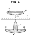
- a first method of attaching the male and female buttons 1, 2 to the cloth using a first assembling tool will now be described. As the male and female buttons 1, 2 are first individually assembled in the same manner, assembling of only the male button 2 is described here.
- the cloth C is placed over the shank 21 of the face plate 4 and then the resilient plate 8 is placed over the cloth C in such manner that the central hole 29 of the resilient plate 8 is axially (vertically in Fig. 4) aligned with the shank 21 of the face plate 4, whereupon the shank 21 is forced into the central hole 29 as pressed by a non-illustrated punch.
- the shank 21 pierces the cloth C and expands the central hole 29 and, as a result, the peripheral edge of the central hole 29 comes to bite the shank 21 so as the cloth C can be firmly held between the face plate 4 and the resilient plate 8.
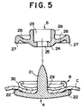
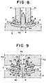
- the snap body 6 is placed over the assembled front plate 4 and resilient plate 8, in such a manner that the axial shank-insertion hole 25 is put in axial alignment with the distal end of the shank 21 as shown in Fig. 5, whereupon the shank 21 is inserted through the axial shank-insertion hole 25. Finally, the distal end of the shank 21 is smashed or clenched by the punch so as to form a swelled portion 31, as shown in Fig. 9, thereby fixing the face plate 4 and the snap body 6 together.
- the cloth C is clamped between the face plate 4 and the resilient plate 8, and the bottom 24 of the plug portion 23 of the snap body 2 presses the resilient plate 8 against the cloth C and the face plate 4 to hold the cloth C firmly in position. Further, since this securing of the cloth C takes place at two positions, i.e., between the resilient plate 8 and the shank 21 and between the shank 21 and the snap body 6, it is possible to catch the cloth C around the shank 21 with increased firmness and to thereby attach the male button 2 to the cloth C much more stably.
- Fig. 6 shows a modification of the male button 2 with a modified face plate 4, the axial shank 21 of which is in a form of a tube having an axial hollow portion 35 at its center and tapering at its open distal end for facilitating piercing the cloth C.
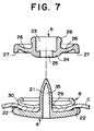
- Fig. 7 shows another modification of the male button 2 with another modified face plate 4, the axial shank 21 of which is in a form of a bullet having an axial hollow portion 35 opening at its base.
- the tubular shank 21 of Fig. 6 is inserted through the snap body 6 and is then smashed or clenched to open wide in the plug portion 23 of the snap body 6.
- the bullet-shape shank of Fig. 7, on the other hand, is inserted through the snap after having been threaded fixedly through the resilient plate 8.
- the face plate 4 having the shank 21 with the hollow portion 35 is preferably made of softer material than the resilient plate 8, or may be made of thermoplastic resin. Alternatively, it may be made of metal such as aluminum alloy, zinc alloy, or etc..
- the resilient plate 8 is preferably made from stainless steel.
- the punch is retracted.
- the snap body 6 held by a tubular third punch P3 is threaded on the shank 21 and then a rod-shaped fourth punch P4 mounted in the third punch P3 is lowered toward the die D to smash and clench the shank 21 projecting into the plug portion 23 of the snap body 6 to form a swelled end 31, thereby fixedly joining the snap body 6 and the shank 21.
- the cloth C is clamped with increased reliability between the face plate 4 and the snap body 6 by synergy of the connection between the resilient plate 8 and the shank 21 and that between the shank 21 and the snap body 6.
- the pressing surface of the tubular third punch P3 is defined partly by an annular cutout 43 at its inner side for receiving the plug portion 23 of the snap body 6 and partly by an annular groove 44 contiguous to and outward of the annular cutout 43 for receiving the peripheral flange 26 of the resilient plate 8.
- the inside wall of the annular cutout 43 of the third punch P3 presses the annular protuberance 28 of the plug portion 23 to thereby hold the male snap body 6.
- a pressing surface of the fourth punch P4 has an uneven surface 47 that serves to reinforce the peripheral edge of a possible swelled end 31 during clenching.
- the foregoing male-button attaching method can be adopted to the attaching of the female button 1.
- a non-illustrated annular projection may be substituted for the cutout 43 in the pressing surface of the third punch 3 to receive the socket portion 12 of the female snap body 5 so that the inside surface of the annular projection comes against the annular ridge 17 of the socket portion 12 to thereby hold the female snap body 5.
- the resilient plate 8 may be pressed in a double step by employing a tubular second punch P2 in addition to the tubular first punch P1.
- the outer-peripheral-edge side, i.e., the curled-edge side of the resilient plate 8 is pressed by the tubular first punch P1 for engagement with the shank 21.
- the pressing surface of the tubular first punch P1 is curved as an arcuate surface 41 complementary to the inner curvature of the resilient plate 8.
- the tubular second punch P2 which is telescopically mounted inside the tubular first punch P1, presses the resilient plate 8.
- the pressing surface of the second punch P2 is flat as a horizontal surface 42 to press the peripheral edge of the central hole 29 of the resilient plate 8.
- the peripheral edge of the central hole 29 of the resilient plate 8 bites relatively deeply into the shank 21 as shown in Fig. 11, thereby clamping the cloth C between the resilient plate 6 and the face plate 4 with increased firmness.
- Fig. 12 shows a modified snap button (only a modified male button 2 is shown) according to a second embodiment of the invention.
- the modified male button 2 like the male button 2 of the first embodiment, is basically composed of a face plate 4, a snap body 6 and a resilient plate 8.
- the face plate 4 is substantially identical in structure with that of the first embodiment, while the snap body 6 and the resilient plate 8 are somehow different in structure from those of the first embodiment.
- the outer surface of a peripheral flange 26 extending from a base end of a modified plug portion 23 is located outward of the outer surface of a bottom 24 of the modified plug portion 23 to form step between them, thereby defining a peripheral recess 32.
- the modified resilient plate 8 is in a form of a slightly curved plate and has a central hole 29.
- the peripheral edge of the central hole 29 is bent inwardly as an inwardly bent inner peripheral edge 33 curving in the same direction as that of the curving of the resulting metal plate.
- the bent inner peripheral edge 33 can be resiliently deformed within the peripheral recess 32 of the snap body 6.
- the modified resilient plate 8 is devoid of any curl in its inner peripheral edge so that the curl-free outer peripheral edge can be embedded in an outwardly bent outer peripheral edge 27 of the peripheral flange 26, thus assuming a stabilized posture on the peripheral flange 26.
- the modified male button 2 is totally identical with that of the first embodiment. The foregoing description of the modified male button 2 can be adopted to the modified female button 1.
- a pressing surface of the alternative tubular first punch P1 is defined partly by an annular cutout 43 at its inner side for receiving the plug portion 23 of the snap body 6 and partly by an annular groove 44 contiguous to and outward of the annular cutout 43 for receiving the peripheral flange 26 of the resilient plate 8.
- the alternative first punch P1 is lowered toward the die D, the inside wall of the annular cutout 43 comes against the annular protuberance 28 of the plug portion 23 to thereby hold the male snap body 6.
- a non-illustrated annular projection may be substituted for the cutout 43 in the pressing surface of the alternative first punch P1 to receive the socket portion 12 of the modified female snap body 5 so that the inside surface of the annular projection comes against the annular ridge 17 of the socket portion 12 to thereby hold the female snap body 5.
- the alternative first punch P1 is retracted away from the die D.
- a solid cylindrical fourth punch P4 is lowered toward the die D to smash and clench the shank 21 in the plug portion 23 of the modified male snap body 6 to form a swelled end 31, thereby fixedly joining the snap body 6 and the shank 21.
- the cloth C is clamped with increased reliability between the modified male face plate 4 and the modified male snap body 6 by synergy of the connection between the resilient plate 8 and the shank 21 and that between the shank 21 and the snap body 6.
- Fig. 15 shows still another modified snap button (only still another modified male button 2 is shown) according to a third embodiment of the invention.
- the modified male button 2 like the male button 2 of the first embodiment, is basically composed of a face plate 4, a snap body 6 and a resilient plate 8.
- Each of the face plate 4 and the snap body 6 is identical in structure with those of the first embodiment, while only the resilient plate 8 is particularly different in structure from that of the first embodiment.
- the modified resilient plate 8 is in a form of a small-sized frustum resilient plate mounted in the plug portion 23 and has a central hole 29 and a radially outwardly bent outer peripheral edge 34.
- the foregoing structural features of the modified male button 2 are identical with those of the modified female button 1.
- the modified male resilient plate 8 is pressed by another alternative tubular first punch P1 to pierce its shank 21 through the cloth C and, at the same time, to thread the shank 21 through the bottom 24 of the plug portion 23 and the small-sized frustoconical resilient plate 8, thereby clamping the cloth C between the face plate 4 and the bottom 14 of the plug portion 24.
- a pressing surface of the further alternative tubular first punch P1 is defined partly by an annular cutout 45 at its inner side for receiving the plug portion 23 of the snap body 6, partly by an annular groove 44 contiguous to and outward of the annular cutout 45 for receiving the peripheral flange 26 of the snap body 6, and partly by an annular projection 46 having an end tapered at the inner side thereof for pressing the frustum resilient plate 8.
- the further alternative first punch P1 is retracted away from the die D.
- the cloth C is clamped between an outward surface of the face plate 4 and the bottom 24 of the snap body 6.
- a solid cylindrical fourth punch P4 is lowered toward the die D to smash and clench the shank 21 in the plug portion 23 of the modified male snap body 6 to form a swelled end 31.
- the swelled end 31 of the shank 21 embraces the inner peripheral edge of the central hole 29 of the small-sized frustoconical resilient plate 8 to thereby secure the frustoconical resilient plate 5 firmly.
- the pressing surface of the solid cylindrical fourth punch P4 is curved as an arcuate surface (as viewed in cross section) 48 to mold an arcuate shape (as viewed in cross section) of the swelled end 31.
- the male and female buttons 2, 1 of the snap button comprises: a male face plate 4 having a smashable shank 21 projecting centrally from its inner surface for piercing a first part of the cloth C; a male snap body 6 having a concave plug portion 23, a first shank-insertion hole 25 extending axially through the plug portion 23, and a peripheral flange 26 extending from a base portion of the plug portion 23 of an inner open end thereof; a male resilient plate 8 adapted to be pierced by the shank 21 so as to press the first part of the cloth C against the inner surface of the male face plate 4; a female face 3 plate having a smashable shank 10 projecting centrally from its inner surface for piercing a second part of the cloth C a female snap body 5 having a concave socket portion 12, a shank-insertion hole 14 extending centrally through the socket portion 12, and a peripheral flange 15 extending from a base portion of the socket portion 12 of an inner open end thereof; and
- each of the male and female resilient plates 8, 7 has an arcuate surface complementary to the inner surface of a respective one of the male and female face plates 4, 3 so that the cloth C can be clamped between the resilient plates 8, 7 and the face plates 4, 3, the face plate and the resilient plate can catch the cloth reliably and easily, thus firm and stable attachment of the snap button can be achieved.
- each of the male and female resilient plates 8, 7 has an inwardly curled peripheral edges 30, 20, and partly since each of the male and female snap bodies 6, 5 has outwardly bent peripheral edges 27, 16, and yet partly since each of the plug and socket portions 23, 12 has outwardly bulging bottoms 24, 13 for pressing a respective one of the male and female resilient plates 8, 7 around its central holes 29, 19, the resilient plate can press the cloth against the face plates 4, 3 by its entire surface to secure the cloth C firmly and stably, realizing a damage-proof tough snap button.
- each resilient plate 8, 7 is embedded in the outer peripheral edge of a respective one of the peripheral flanges 26, 15 of the male and female snap bodies 6, 5, it is possible to secure the resilient plates 8, 7 to the snap bodies 6, 5 reliably and firmly so that the resilient plates 8, 7 can be engaged with the shanks 21, 10 in a stabilized posture with increased reinforcement.
- each of the male and female resilient plates 8, 7 has a central hole smaller in diameter than the respective shanks 21, 10 and partly since a peripheral edge of the central holes 21, 10 is in biting engagement with the respective shank, it is possible to join the shanks 21, 10 of the face plates 4, 3 and the resilient plates 8, 7 together firmly without being accidentally removed off each other.
- each resilient plate 8, 7 is initially devoid of any central hole and is adapted to be pierced by a respective one of the shanks 21, 10 under pressure, it is possible to join the shank of the face plates 4, 3 and the resilient plates 8, 7 together simply and firmly without being accidentally removed off each other.
- each of the peripheral flanges 26, 15 of the male and female snap bodies 6, 5 is located outward of the bottoms 24, 13 of a respective one of the plug and socket portions 23, 12, and partly since each of the resilient plates 8, 7 is superposed on an outer surface of a respective one of peripheral flanges 26, 15, and yet partly since each of the male and female snap bodies 6, 5 has around a respective one of the shank-insertion holes 25, 14 a peripheral recess 32 for allowing each of the resilient plates 8, 7 to deform, it is possible to locate the resilient plate in a stabilized posture against the snap body and to facilitate resilient deformation of the resilient plate and also to clamp and secure the cloth margin without difficulty.
- each resilient plates 8, 7 since the peripheral edge of the central holes 29, 19 of each resilient plates 8, 7 is inwardly bent so as to bite into a respective one of the shanks 23, 12, it is possible to thread the shanks 21, 10 of the face plates 4, 3 through the snaps bodies 6, 5 reliably and simply and to engage the shanks 21, 10 with the resilient plates 8, 7 firmly without accidental removal.
- each of the resilient plates 8, 7 is a small-sized frustum resilient plates 8, 7 mounted in a respective one of the concave plug and socket portions 23, 12, and yet partly since each shank 21, 10 is smashed so as to engage the frustum resilient plates 8, 7, it is possible to engage the resilient plates 8, 7 with the shanks 21, 10 of the face plates 4, 3 simply and reliably and to achieve adequate engagement by the small-sized resilient plate so that material to be used can be saved, thus resulting in reduction of price.
- each of the face plates 4, 3 is made of a material softer than that of each of the resilient plates 8, 7 and partly since the shanks 21, 10 of each face plates 4, 3 has an axial hollow portion therein, it is possible to smash or clench the shanks 21, 10 when the face plates 4, 3 are attached to the snap bodies 6, 5 so that the snap button can be attached to the cloth quickly and reliably, thus improving the attaching efficiency.
- each of the face plates 4, 3 and each of the snap bodies 6, 5 are molded of thermoplastic resin and partly since each of the resilient plates 7, 8 is made from a metal plate, it is possible to achieve reliable engagement using optimum materials for the snap bodies 6, 5, the face plates 4, 3 and the resilient plates 8, 7 so that reliable engagement can be achieved. As a result, an ideal snap button can be realized.
- a method of attaching a snap button to a cloth comprises a first step of piercing the shanks 21, 10 of the face plates 4, 3 of each of the male and female buttons 2, 1 through a respective one of first and second parts of the cloth C, inserting the shanks 21, 10 through the central holes 29, 19, which is smaller in diameter than the shanks 21, 10, of the resilient plates 8, 7 to clamp a respective one of the first and second part of the cloth C between the resilient plates 8, 7 and the face plates 4, 3, and a second step of pressing the shanks 21, 10, which is inserted through the shank-insertion holes 6, 5 of the snap bodies 6, 5 of each of the male and female buttons 2, 1 to smash the shanks 21, 10 in the snap bodies 6, 5, it is possible to secure each of the snap bodies 6, 5 of the snap button to the shanks 21, 10 of each face plate 4, 3 firmly at two positions using the respective resilient plates 8, 7 and also to perform intermediate inspection between the first and second steps by the operator's eyes so that reliable checking can
- the resilient plates 8, 7 are pressed first at their outer peripheral edge and then at a peripheral edge of the central holes 29, 19 to bring the resilient plates 8, 7 into engagement with the shanks 21, 10 of the face plates 4, 3, the peripheral edge of the central hole 19 can be sufficiently deformed.
- the peripheral edge can be bite into the shanks 21, 10, it is possible to clamp the cloth simply and firmly.
- the resilient plates 8, 7 with the peripheral edge of the central holes 29, 19 resiliently deformable are superposed over the inner surface of each of the male and female snap bodies 6, 5, and each of the resilient plates 8, 7 is pressed against each snap body 6, 5, thereby engaging each shank 21, 10 of each face plate 4, 3.
- each of the snap bodies 6, 5 and a respective one of the first and second part of the cloth are threaded on each shank 21, 10 of the face plates 4, 3, and partly since a small-sized resilient plate 8, 7 is then threaded on each shank 21, 10 and is pressed against each snap body 6, 5, thereby engaging each shank 21, 10 of each face plate 4, 3, it is possible to perform both threading of the snap bodies 6, 5 and the small-sized resilient plates 8, 7 onto the shanks 21, 10 of the face plates 4, 3 as a unitary structure and pressing of these members once for all, thus improving the rate of production.
Landscapes
- Slide Fasteners, Snap Fasteners, And Hook Fasteners (AREA)
Applications Claiming Priority (2)
| Application Number | Priority Date | Filing Date | Title |
|---|---|---|---|
| JP192098/97 | 1997-07-17 | ||
| JP9192098A JPH1132815A (ja) | 1997-07-17 | 1997-07-17 | スナップボタンおよびその取付方法 |
Publications (2)
| Publication Number | Publication Date |
|---|---|
| EP0891723A2 true EP0891723A2 (fr) | 1999-01-20 |
| EP0891723A3 EP0891723A3 (fr) | 1999-04-07 |
Family
ID=16285624
Family Applications (1)
| Application Number | Title | Priority Date | Filing Date |
|---|---|---|---|
| EP98113407A Withdrawn EP0891723A3 (fr) | 1997-07-17 | 1998-07-17 | Bouton-pression et son procédé de fixation |
Country Status (4)
| Country | Link |
|---|---|
| US (1) | US5933929A (fr) |
| EP (1) | EP0891723A3 (fr) |
| JP (1) | JPH1132815A (fr) |
| CA (1) | CA2242810A1 (fr) |
Cited By (8)
| Publication number | Priority date | Publication date | Assignee | Title |
|---|---|---|---|---|
| WO2006125236A3 (fr) * | 2005-05-23 | 2008-12-04 | Reinhold Stumpfl | Dispositif d'assemblage |
| CN103079421A (zh) * | 2010-11-16 | 2013-05-01 | Ykk株式会社 | 按扣的制造方法及凸按扣 |
| US20130117972A1 (en) * | 2010-07-26 | 2013-05-16 | Kenji Hasegawa | Button Fixing Member and Button Structure |
| CN102573540B (zh) * | 2009-10-22 | 2014-10-22 | Ykk株式会社 | 钮扣安装方法、钮扣安装系统和钮扣安装用上模 |
| DE102008050791B4 (de) * | 2007-10-09 | 2016-05-04 | Ykk Corp. | Wassermigrationsbeständiger Schnappverschluss |
| CN113729363A (zh) * | 2021-08-24 | 2021-12-03 | 宏基钮扣(石狮)有限公司 | 一种按压纽扣组件及其使用方法 |
| EP3348162B1 (fr) * | 2015-09-11 | 2023-03-22 | YKK Corporation | Bouton-pression |
| US11930895B2 (en) | 2020-11-03 | 2024-03-19 | The Beer Vest Guys Llc | Garment for displaying ornaments |
Families Citing this family (79)
| Publication number | Priority date | Publication date | Assignee | Title |
|---|---|---|---|---|
| RU2182810C1 (ru) * | 2000-10-16 | 2002-05-27 | Савельев Вадим Николаевич | Кнопка-застежка |
| KR100815129B1 (ko) * | 2001-08-14 | 2008-03-20 | 코닌클리케 필립스 일렉트로닉스 엔.브이. | 스위치, 의복, 및 직물 물건 |
| GB2390112B (en) * | 2002-06-26 | 2005-09-07 | Michael John Stubbs | Snap fastener for use with fabrics |
| US7698836B2 (en) * | 2005-07-07 | 2010-04-20 | Jibbitz, Llc | System and method for securing accessories to clothing |
| US8122519B2 (en) * | 2005-07-07 | 2012-02-28 | Jibbitz, Llc | System and method for securing accessories to wearable items |
| US7735235B2 (en) * | 2005-09-29 | 2010-06-15 | Ez-Snap Products Inc. | Marking and fastening device and method of using same |
| US8122572B2 (en) * | 2005-09-29 | 2012-02-28 | Ez-Snap Products Inc. | Marking and fastening device and method of using same |
| US20070084019A1 (en) * | 2005-10-17 | 2007-04-19 | Rob Wilcox | Ornamental rivet apparatus especially for clothing or shoes |
| US8069538B2 (en) * | 2006-03-10 | 2011-12-06 | Robert Wilcox | Apparatus and method for securely yet removably attaching ornaments to shoes, clothing, pet collars and the like |
| US7374448B2 (en) * | 2006-11-03 | 2008-05-20 | Cadwell Lab Inc | Electrical connector locking system |
| FR2925929B1 (fr) * | 2007-12-28 | 2017-01-27 | Saint Gobain Isover | Accessoire d'entretoisement pour le doublage d'une paroi, comportant des machoires de pincement d'une membrane isolante et dispositif de doublage de paroi comportant un tel accessoire |
| CA128404S (en) | 2008-10-22 | 2010-11-15 | Ez Snap Products Inc | Pin device for marking and fastening shades |
| JP5579200B2 (ja) * | 2009-12-25 | 2014-08-27 | Ykk株式会社 | 雄スナップボタン取付方法及び雌スナップボタン取付方法 |
| USD678816S1 (en) | 2010-12-23 | 2013-03-26 | Duraflex Hong Kong Limited | Snap button assembly |
| USD642089S1 (en) | 2010-12-23 | 2011-07-26 | Duraflex Hong Kong Limited | Portion of a snap button |
| US20120192384A1 (en) * | 2011-01-31 | 2012-08-02 | Rayanne Kelly | Adjustable Utility Strap |
| JP5953615B2 (ja) * | 2011-04-21 | 2016-07-20 | Ykk株式会社 | スナップボタン |
| JP5929009B2 (ja) * | 2011-05-16 | 2016-06-01 | 横浜ゴム株式会社 | 空気入りタイヤ |
| CN103717101B (zh) * | 2011-08-04 | 2016-01-20 | Ykk株式会社 | 按扣的形成方法、按扣中间件以及按扣 |
| USD664891S1 (en) * | 2011-11-09 | 2012-08-07 | Takeda Seiki, Co., Ltd. | Male part of a snap button |
| USD665304S1 (en) * | 2011-11-09 | 2012-08-14 | Takeda Seiki, Co., Ltd. | Female part of a snap button |
| USD689395S1 (en) | 2012-01-05 | 2013-09-10 | Duraflex Hong Kong Limited | Snap button |
| US10165811B2 (en) * | 2012-01-27 | 2019-01-01 | The Cozmix Inc. | Interchangeable fabric accessory and method of use |
| US20130302541A1 (en) * | 2012-05-10 | 2013-11-14 | Kathlene Lynn Morgan | Special interchangeable accessory line device and the business method for its implementation as an enterprise |
| JP2014019791A (ja) * | 2012-07-18 | 2014-02-03 | Asahi Kasei Chemicals Corp | ポリアミド樹脂組成物よりなるプラスチックホック成形体 |
| USD700864S1 (en) * | 2012-10-12 | 2014-03-11 | Suunto Oy | Module assembly |
| USD701140S1 (en) * | 2012-10-12 | 2014-03-18 | Suunto Oy | Module |
| ITMI20121953A1 (it) * | 2012-11-16 | 2014-05-17 | Fimma S P A A Socio Unico | Bottone a pressione bivalente con chiusura a doppio scatto. |
| KR102170512B1 (ko) * | 2014-03-21 | 2020-10-27 | 삼성전자주식회사 | 웨어러블 장치의 스트랩 체결장치 |
| JP2016141907A (ja) * | 2015-02-03 | 2016-08-08 | 武田精機株式会社 | スナップファスナー取付け用カシメパンチ及び取付け機 |
| KR101684606B1 (ko) * | 2015-04-23 | 2016-12-08 | 유승민 | 아일릿부재 및 그 제조방법 |
| CN106307840A (zh) * | 2015-06-24 | 2017-01-11 | 鸿富锦精密电子(郑州)有限公司 | 表扣、使用该表扣的表带及扣件 |
| US20170035165A1 (en) * | 2015-08-05 | 2017-02-09 | Aevoe International Ltd. | Pad for protective cover |
| US10232770B2 (en) * | 2015-09-08 | 2019-03-19 | Ykk Corporation Of America | Illuminated marker |
| US10064441B1 (en) * | 2016-02-12 | 2018-09-04 | Boston Inventions, LLC | Locking button system |
| CN109414082B (zh) * | 2016-08-08 | 2020-12-15 | Ykk株式会社 | 按扣安装检査装置 |
| US11241297B2 (en) | 2016-12-12 | 2022-02-08 | Cadwell Laboratories, Inc. | System and method for high density electrode management |
| WO2018231826A1 (fr) | 2017-06-12 | 2018-12-20 | Yeti Coolers, Llc | Contenant et système de verrouillage |
| US11019886B2 (en) * | 2017-06-12 | 2021-06-01 | Ykk Corporation | Button |
| US12108853B2 (en) | 2019-01-06 | 2024-10-08 | Yeti Coolers, Llc | Luggage system |
| US11976498B2 (en) | 2017-06-12 | 2024-05-07 | Yeti Coolers, Llc | Container and latching system |
| US11685573B2 (en) | 2017-06-12 | 2023-06-27 | Yeti Coolers, Llc | Carry strap for container |
| AU201717615S (en) | 2017-06-12 | 2018-01-15 | Yeti Coolers | Container |
| US10066658B1 (en) * | 2017-08-01 | 2018-09-04 | Ykk Corporation Of America | Non-rotatable fastener assembly and associated methods |
| US10130148B1 (en) * | 2017-11-30 | 2018-11-20 | Duraflex Hong Kong Limited | Snap button |
| KR102011047B1 (ko) * | 2018-03-23 | 2019-08-14 | 홍성민 | 스냅단추 및 그 결합방법 |
| US11517239B2 (en) | 2018-04-05 | 2022-12-06 | Cadwell Laboratories, Inc. | Systems and methods for processing and displaying electromyographic signals |
| US11596337B2 (en) | 2018-04-24 | 2023-03-07 | Cadwell Laboratories, Inc | Methods and systems for operating an intraoperative neurophysiological monitoring system in conjunction with electrocautery procedures |
| US11185684B2 (en) | 2018-09-18 | 2021-11-30 | Cadwell Laboratories, Inc. | Minimally invasive two-dimensional grid electrode |
| US11517245B2 (en) | 2018-10-30 | 2022-12-06 | Cadwell Laboratories, Inc. | Method and system for data synchronization |
| US12533069B2 (en) | 2018-11-09 | 2026-01-27 | Cadwell Laboratories, Inc. | Systems and methods of electrode switching for neurophysiological sensing and stimulation |
| US11471087B2 (en) | 2018-11-09 | 2022-10-18 | Cadwell Laboratories, Inc. | Integrity verification system for testing high channel count neuromonitoring recording equipment |
| US11317841B2 (en) | 2018-11-14 | 2022-05-03 | Cadwell Laboratories, Inc. | Method and system for electrode verification |
| US11529107B2 (en) | 2018-11-27 | 2022-12-20 | Cadwell Laboratories, Inc. | Methods for automatic generation of EEG montages |
| USD907445S1 (en) | 2018-12-11 | 2021-01-12 | Yeti Coolers, Llc | Container accessories |
| USD904829S1 (en) | 2018-12-11 | 2020-12-15 | Yeti Coolers, Llc | Container accessories |
| MX2021008199A (es) | 2019-01-06 | 2021-11-12 | Yeti Coolers Llc | Sistema de equipaje. |
| US12225993B2 (en) | 2019-01-06 | 2025-02-18 | Yeti Coolers, Llc | Luggage system |
| US11128076B2 (en) | 2019-01-21 | 2021-09-21 | Cadwell Laboratories, Inc. | Connector receptacle |
| IT201900006676A1 (it) * | 2019-05-09 | 2019-08-09 | Specialinsert S R L | Chiusura a scatto con regolazione della tensione di scatto |
| US11312317B2 (en) * | 2019-06-03 | 2022-04-26 | Teijin Automotive Technologies, Inc. | Vehicle headliner system and method for installing the same |
| CN110638153B (zh) * | 2019-08-30 | 2022-06-03 | 宏基钮扣(石狮)有限公司 | 一种高精度钮扣 |
| US11219283B2 (en) * | 2020-04-14 | 2022-01-11 | Bradford M. Bird | Conjoining assembly |
| US10869518B1 (en) * | 2020-05-05 | 2020-12-22 | Lionhead Helmet Intellectual Properties, Lp | Chin strap assembly for a protective helmet |
| USD941702S1 (en) | 2020-05-22 | 2022-01-25 | Bradford M. Bird | Conjoining device |
| USD951643S1 (en) | 2020-06-30 | 2022-05-17 | Yeti Coolers, Llc | Luggage |
| USD961926S1 (en) | 2020-06-30 | 2022-08-30 | Yeti Coolers, Llc | Luggage |
| USD963344S1 (en) | 2020-06-30 | 2022-09-13 | Yeti Coolers, Llc | Luggage |
| USD954436S1 (en) | 2020-06-30 | 2022-06-14 | Yeti Coolers, Llc | Luggage |
| TWI827998B (zh) * | 2020-11-04 | 2024-01-01 | 美商卡斯登製造公司 | 具有配接鉚釘之按扣系統 |
| USD994438S1 (en) | 2020-12-16 | 2023-08-08 | Yeti Coolers, Llc | Container |
| USD985937S1 (en) | 2020-12-16 | 2023-05-16 | Yeti Coolers, Llc | Container |
| USD960648S1 (en) | 2020-12-16 | 2022-08-16 | Yeti Coolers, Llc | Container accessory |
| US11622605B2 (en) * | 2021-03-19 | 2023-04-11 | Jezekiel Ben-Arie | Button attachment by resilient gates trapping mechanism |
| US11219277B1 (en) * | 2021-03-19 | 2022-01-11 | Jezekiel Ben-Arie | Fast button attachment by resilient flaps trapping |
| US12514549B2 (en) | 2021-08-31 | 2026-01-06 | Cadwell Laboratories, Inc. | Methods and systems for evaluating echo data contemporaneous with an electrodiagnostic study |
| USD1062525S1 (en) | 2021-12-24 | 2025-02-18 | Ykk Corporation | Snap button |
| US11528963B1 (en) * | 2022-06-30 | 2022-12-20 | Joybees LLC | Systems, devices, and methods for securing a decorative component to footwear |
| WO2024128595A1 (fr) * | 2022-12-13 | 2024-06-20 | 김나연 | Ensemble |
Family Cites Families (8)
| Publication number | Priority date | Publication date | Assignee | Title |
|---|---|---|---|---|
| US503081A (en) * | 1893-08-08 | Glove-fastener | ||
| US1832830A (en) * | 1928-09-27 | 1931-11-17 | Scovill Manufacturing Co | Resilient snap fastener element |
| US2799910A (en) * | 1953-07-02 | 1957-07-23 | Bonnie M Weber | Snap fastener ornament cap assembly |
| US3195201A (en) * | 1963-04-17 | 1965-07-20 | Scovill Manufacturing Co | Ornamental snap fastener assembly |
| US3229343A (en) * | 1963-11-06 | 1966-01-18 | United Carr Inc | Snap fastener socket |
| JPS58164512U (ja) * | 1981-12-07 | 1983-11-01 | 日本ノ−シヨン工業株式会社 | 被服用スナツプ |
| JPS5986111U (ja) * | 1982-12-01 | 1984-06-11 | 日本ノ−シヨン工業株式会社 | スナツプ釦の雌体 |
| DE3932907C1 (en) * | 1989-10-03 | 1990-05-10 | Stocko Metallwarenfabriken Henkels Und Sohn Gmbh & Co, 5600 Wuppertal, De | Watertight press-stud for flat materials - incorporates two interlocking components gripping material |
-
1997
- 1997-07-17 JP JP9192098A patent/JPH1132815A/ja active Pending
-
1998
- 1998-07-10 CA CA002242810A patent/CA2242810A1/fr not_active Abandoned
- 1998-07-17 EP EP98113407A patent/EP0891723A3/fr not_active Withdrawn
- 1998-07-17 US US09/118,364 patent/US5933929A/en not_active Expired - Fee Related
Cited By (12)
| Publication number | Priority date | Publication date | Assignee | Title |
|---|---|---|---|---|
| WO2006125236A3 (fr) * | 2005-05-23 | 2008-12-04 | Reinhold Stumpfl | Dispositif d'assemblage |
| CN101426392B (zh) * | 2005-05-23 | 2013-01-23 | 赖因霍尔德·施廷普菲尔 | 连接装置 |
| US8371361B2 (en) | 2005-05-23 | 2013-02-12 | Reinhold Stumpfl | Connecting device |
| DE102008050791B4 (de) * | 2007-10-09 | 2016-05-04 | Ykk Corp. | Wassermigrationsbeständiger Schnappverschluss |
| CN102573540B (zh) * | 2009-10-22 | 2014-10-22 | Ykk株式会社 | 钮扣安装方法、钮扣安装系统和钮扣安装用上模 |
| US20130117972A1 (en) * | 2010-07-26 | 2013-05-16 | Kenji Hasegawa | Button Fixing Member and Button Structure |
| US9060572B2 (en) * | 2010-07-26 | 2015-06-23 | Ykk Corporation | Button fixing member and button structure |
| DE112010005770B4 (de) | 2010-07-26 | 2024-04-18 | Ykk Corporation | Knopfbefestigungsteil und Knopfanordnung |
| CN103079421A (zh) * | 2010-11-16 | 2013-05-01 | Ykk株式会社 | 按扣的制造方法及凸按扣 |
| EP3348162B1 (fr) * | 2015-09-11 | 2023-03-22 | YKK Corporation | Bouton-pression |
| US11930895B2 (en) | 2020-11-03 | 2024-03-19 | The Beer Vest Guys Llc | Garment for displaying ornaments |
| CN113729363A (zh) * | 2021-08-24 | 2021-12-03 | 宏基钮扣(石狮)有限公司 | 一种按压纽扣组件及其使用方法 |
Also Published As
| Publication number | Publication date |
|---|---|
| JPH1132815A (ja) | 1999-02-09 |
| US5933929A (en) | 1999-08-10 |
| EP0891723A3 (fr) | 1999-04-07 |
| CA2242810A1 (fr) | 1999-01-17 |
Similar Documents
| Publication | Publication Date | Title |
|---|---|---|
| US5933929A (en) | Snap button and method of attaching the same | |
| US4607415A (en) | Button for garment | |
| US4716634A (en) | Two-piece reinforced clothes peg | |
| US5797170A (en) | Synthetic resin molded surface fastener | |
| EP0876775B1 (fr) | Elément de fixation pour bouton | |
| CA1187676A (fr) | Bouton-pression pour vetements | |
| US7013539B2 (en) | Weld button for garments | |
| US4706344A (en) | Button assembly | |
| US4698881A (en) | Socket element assembly for snap fasteners | |
| EP0110350A1 (fr) | Ensemble de bouton pression | |
| US4570307A (en) | Button having plate for deflecting an attaching tack | |
| US5673463A (en) | Belt with a micro-adjustment buckle | |
| EP0123215B1 (fr) | Bouton | |
| EP1110469A2 (fr) | Tige d'assemblage de bouton à queue et contrepièce | |
| CA2068783C (fr) | Bouton-pression | |
| US7021718B2 (en) | Method and apparatus for attaching accessories to load-bearing fabric | |
| US5107573A (en) | Rotating connector | |
| US4686749A (en) | Capped eyelet for attaching snap fastener | |
| US3696470A (en) | Plastic fastener and method of securing same to material | |
| US4761863A (en) | Structure of snap | |
| EP0610812B1 (fr) | Agrafe à crochet et à oeillet | |
| EP0146133A2 (fr) | Tête de rivet pour la fixation d'un bouton pression à un vêtement | |
| CN215762681U (zh) | 一种中空式环形卡扣组件 | |
| JP3066832U (ja) | 樹脂製カップルリベット | |
| EP4193872B1 (fr) | Dispositif de sécurité à bouton doté d'une broche amovible et d'une partie de base |
Legal Events
| Date | Code | Title | Description |
|---|---|---|---|
| PUAI | Public reference made under article 153(3) epc to a published international application that has entered the european phase |
Free format text: ORIGINAL CODE: 0009012 |
|
| AK | Designated contracting states |
Kind code of ref document: A2 Designated state(s): DE FR GB |
|
| AX | Request for extension of the european patent |
Free format text: AL;LT;LV;MK;RO;SI |
|
| PUAL | Search report despatched |
Free format text: ORIGINAL CODE: 0009013 |
|
| AK | Designated contracting states |
Kind code of ref document: A3 Designated state(s): AT BE CH CY DE DK ES FI FR GB GR IE IT LI LU MC NL PT SE |
|
| AX | Request for extension of the european patent |
Free format text: AL;LT;LV;MK;RO;SI |
|
| 17P | Request for examination filed |
Effective date: 19990719 |
|
| AKX | Designation fees paid |
Free format text: DE FR GB |
|
| STAA | Information on the status of an ep patent application or granted ep patent |
Free format text: STATUS: THE APPLICATION IS DEEMED TO BE WITHDRAWN |
|
| 18D | Application deemed to be withdrawn |
Effective date: 20000801 |