EP0891724A2 - Crochets pour fermeture auto-agrippante pourvus d'un dispositif d'espacement ainsi que leur procédé de fabrication - Google Patents
Crochets pour fermeture auto-agrippante pourvus d'un dispositif d'espacement ainsi que leur procédé de fabrication Download PDFInfo
- Publication number
- EP0891724A2 EP0891724A2 EP97118005A EP97118005A EP0891724A2 EP 0891724 A2 EP0891724 A2 EP 0891724A2 EP 97118005 A EP97118005 A EP 97118005A EP 97118005 A EP97118005 A EP 97118005A EP 0891724 A2 EP0891724 A2 EP 0891724A2
- Authority
- EP
- European Patent Office
- Prior art keywords
- spacer
- velcro fastener
- holding part
- shape
- molding compound
- Prior art date
- Legal status (The legal status is an assumption and is not a legal conclusion. Google has not performed a legal analysis and makes no representation as to the accuracy of the status listed.)
- Granted
Links
- 125000006850 spacer group Chemical group 0.000 title claims abstract description 43
- 238000000034 method Methods 0.000 title claims description 9
- 238000004519 manufacturing process Methods 0.000 title claims description 7
- 239000000853 adhesive Substances 0.000 claims abstract description 23
- 230000001070 adhesive effect Effects 0.000 claims abstract description 23
- 235000001674 Agaricus brunnescens Nutrition 0.000 claims abstract description 5
- 238000000465 moulding Methods 0.000 claims description 14
- 150000001875 compounds Chemical class 0.000 claims description 7
- 238000005266 casting Methods 0.000 claims description 4
- 238000005507 spraying Methods 0.000 claims description 3
- 238000001125 extrusion Methods 0.000 claims description 2
- 230000002093 peripheral effect Effects 0.000 claims description 2
- WZZBNLYBHUDSHF-DHLKQENFSA-N 1-[(3s,4s)-4-[8-(2-chloro-4-pyrimidin-2-yloxyphenyl)-7-fluoro-2-methylimidazo[4,5-c]quinolin-1-yl]-3-fluoropiperidin-1-yl]-2-hydroxyethanone Chemical compound CC1=NC2=CN=C3C=C(F)C(C=4C(=CC(OC=5N=CC=CN=5)=CC=4)Cl)=CC3=C2N1[C@H]1CCN(C(=O)CO)C[C@@H]1F WZZBNLYBHUDSHF-DHLKQENFSA-N 0.000 description 7
- 239000000463 material Substances 0.000 description 7
- 239000011159 matrix material Substances 0.000 description 4
- 238000005516 engineering process Methods 0.000 description 2
- 108010010803 Gelatin Proteins 0.000 description 1
- 230000001427 coherent effect Effects 0.000 description 1
- 239000002131 composite material Substances 0.000 description 1
- 230000001419 dependent effect Effects 0.000 description 1
- 229920000159 gelatin Polymers 0.000 description 1
- 239000008273 gelatin Substances 0.000 description 1
- 235000019322 gelatine Nutrition 0.000 description 1
- 235000011852 gelatine desserts Nutrition 0.000 description 1
- 238000002347 injection Methods 0.000 description 1
- 239000007924 injection Substances 0.000 description 1
- 238000005192 partition Methods 0.000 description 1
- 238000009423 ventilation Methods 0.000 description 1
Images

Classifications
-
- A—HUMAN NECESSITIES
- A44—HABERDASHERY; JEWELLERY
- A44B—BUTTONS, PINS, BUCKLES, SLIDE FASTENERS, OR THE LIKE
- A44B18/00—Fasteners of the touch-and-close type; Making such fasteners
- A44B18/0046—Fasteners made integrally of plastics
- A44B18/0061—Male or hook elements
-
- A—HUMAN NECESSITIES
- A44—HABERDASHERY; JEWELLERY
- A44B—BUTTONS, PINS, BUCKLES, SLIDE FASTENERS, OR THE LIKE
- A44B18/00—Fasteners of the touch-and-close type; Making such fasteners
- A44B18/0046—Fasteners made integrally of plastics
- A44B18/0049—Fasteners made integrally of plastics obtained by moulding processes
Definitions
- the invention relates to a Velcro fastener with at least one adhesive part, which has at least one connecting part on the head side, which has a spacer is connected to a holding part arranged on the foot side.
- the invention also relates to a method for producing such a Velcro fastener.
- Velcro fasteners as disclosed for example in DE 29 29 329 A1 are common fastening systems today with a variety of Possible applications, for example in the clothing industry or in automotive technology for attaching various objects or parts of Objects with each other.
- the Velcro fastener is usually formed in two parts, the connecting parts of one part of the chain fastener a hook shape, a mushroom shape, an arrow shape, a horn shape or the like. have and with an appropriate loop or loop material of the other part of the Velcro fastener work together, as soon as the addressed parts of the Velcro fastener are placed on top of each other and be squeezed together.
- the closure in question is can be released again with the usual actuation forces, with the "Connect” and "Disconnect” steps as often as you like in the usual service life have such closures made.
- Velcro fasteners for this purpose also for fastening Panels and covers used on a basic vehicle structure.
- the problem often arises that there are large distances between the basic vehicle structure and the object to be fastened are to be bridged. With The usual distances cannot be obtained with the usual Velcro fasteners achieve.
- the adhesive part of the Velcro fastener has at least one spacer, the connection with the other part of the Velcro fastener in the form of a loop or Loop material producing respective connecting part usually in the form of a Hook or mushroom shape at a greater distance from the foot side Bring the holding part, using the spacer used here a support for the opposite loop or loop material the other part of the Velcro fastener forms with the consequence that despite increased distance a secure bond between the two parts of the Velcro fastener is achieved.
- the method for producing such a Velcro fastener is thereby characterized in that at least for the respective spacers and the respective Spacers of each adhesive part with a casting or spraying die Predefinable shape recesses is provided, which are superimposed congruently and be filled with a molding compound provided for this purpose.
- one part of the Velcro fastener has a large number seen in rows next to each other and one behind the other in the image plane arranged adhesive parts 10.
- the respective adhesive part 10 has a connecting part 12 on the head side a triangular shape seen in the direction of Fig.1.
- the respective Connecting part 12 is via a rod-like spacer 14 with a foot side arranged holding part 16 of the adhesive part 10 connected, the holding parts 16 to form a coherent band to form the Velcro fastener are interconnected.
- the respective adhesive part 10 has at least one Spacer 18 on.
- the respective spacer 18 can, as shown in FIG. 1, on the end face viewed in the manner of arms left and right over the spacer 14 protrude and thus be part of the spacer 14; but there is also Possibility to use the spacer 18, as shown in FIG. 2, as part of the Holding part 16 in one piece with this.
- FIG.3 seen the lower half of the picture shows a perspective section of the part the Velcro fastener, as shown in Fig.1 from the front 3, for the sake of simplicity, only one adhesive part 10 is shown.
- the holding part 16 is a band-like structure and that the spacer 18 in shape a partition plate is formed and the rod-like or plate-like spacer 14 extends approximately in the middle.
- the connecting part 12 in the manner of an arrow stands with its marginal surfaces over the marginal surfaces of the spacer 14 before, so that along the longitudinal direction of the upper end of the spacer 14 two longitudinal hooks 20 are formed, the engagement of a loop or Loop material (not shown) are used that are not part of the other shown part of the Velcro fastener are.
- the plate-like spacers form 18 a substantially uniformly extending plane, which in its Alignment runs parallel to the band-like holding part 16. Between Spacers 18 adjacent adhesive parts 10 there is only a slight axial distance that prevents the Loop or loop material of the other part of the Velcro fastener between the distances thus formed, what the intended connection could affect. Rather, they are the connecting parts 12 facing tops of the plate-like spacers 18 arranged such that this is a support surface for the loop or loop material to be placed form. Due to the axial distance between the respective spacers 18 and the top of the holding parts 16 facing them is a Free space formed, which may be the rear ventilation of the to be manufactured Association serves.
- the respective connecting part 12 also have a shape as shown in the upper half of the figure Figure 3 is shown, looking in the direction of Figure 3 from left to right seen a hook shape, a T shape, a mushroom shape, a horn shape as well an arrow shape for the connecting part 12 are realized.
- Other other designs are possible and depend on the specific application from.
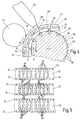
- the method for producing the above-mentioned Velcro fastener is explained in more detail below with reference to FIGS. 4 and 5.
- the method is characterized in that, at least for the respective spacer 14 and the respective spacer 18 of an adhesive part 10, a casting or spraying die 22, 24 and 26 is provided with predeterminable mold recesses 28, which are superimposed congruently and filled with a molding compound 30 provided for this purpose .
- a casting or spraying die 22, 24 and 26 is provided with predeterminable mold recesses 28, which are superimposed congruently and filled with a molding compound 30 provided for this purpose .
- a perforation 32 which are superimposed by a conveying means 34.
- the conveying means 34 is circular in cross-section and is designed as a longitudinal roller (not shown).
- the conveying means 34 is also provided on the outer peripheral side with shaped recesses 28, so that the conveying means 34 can be regarded as part of a further die 36.
- the respective connecting part 12 according to FIG. 1 and FIG. 3 (lower half of the figure) is produced by filling it with the molding compound 30 via the respective recess 28 in the form of a wedge in the further die 36.
- the further die 36 thus forms a type of form roller, the outer circumference has the shape recesses 28 for the respective connecting part 12 and is provided on the edge with driver elements 38 in the manner of triangular serrations, as exemplified and partly in Fig.4 on the right are shown.
- driver elements 38 are at least partially for the Engagement with the perforations 32 of the other matrices 22, 24 and 26 in this way provided that their shape recesses 28 assigned one above the other are successively transportable to a corresponding feed station 40 and can be filled with the molding compound 30.
- the feed station 40 is formed in the manner of an extrusion device with which as a molding compound 30 extrudable plastic in the superimposed mold recesses 28 of the matrices 22, 24 and 26 is filled.
- Fig.4 shows, the die side 42 facing the feed station 40 of FIG 5 seen bottom 26 die to produce the holding part 16 covered with the molding compound 30.
- One in the axial direction to the roller-like Conveying means 34 opposing pressure roller 44 prevented an early lifting of the composite material to be created from the Funding 34.
- the drive directions of conveyor roller 34 and pressure roller 44 are in the Fig.4 indicated with arrows.
- the three matrices 22, 24 and 26 are in the direction of view 4 seen from the right over a not shown Delivery station pulled on the conveyor roller 36, the associated with each other Form recesses 28 to form an adhesive part 10 according to the Fig. 1 run congruently one above the other, what through the transport intervention of the driver elements 38 into the associated perforations 32 at least one die is relieved.
- the perforations 32 are on the edge like a film perforation along the long sides of the individual matrices 22,24 and 26 arranged. As long as a supply of the matrix material takes place and the molding compound 30 via the feed station 40, is a quasi-continuous Operation for producing a Velcro fastener of the above Kind possible.
- the skilful stacking of the matrices results in a combination a casting or injection mold to be filled in, as viewed in the direction 4 is shown at the top.
- this adhesive part form to be filled comes under the feed area the feed station 40 and is filled with molding compound 30.
- Already filled out Molds are then continued in the roll transport direction and by the Roller 34 lifted off.
- Components of the respective adhesive part 10 remaining matrix material is removed, which is particularly easy when the matrix material is made Gelatin or the like is formed.
- A is preferably used as the matrix material Material selected that is recyclable.
- the adhesive part produced in each case when dies 22, 24 and 26 are used 5 results in a circular, rod-like structure for the spacer 14, the diameter of that part of the spacer 14 which corresponds to the Holding part 16 is facing, in diameter compared to the head side Spacer 14 is slightly enlarged.
- the plate-like basic structure for the spacer 18 remains with regard to the design of the mold recess 28 received in the die 24.
Landscapes
- Slide Fasteners, Snap Fasteners, And Hook Fasteners (AREA)
- Injection Moulding Of Plastics Or The Like (AREA)
- Package Frames And Binding Bands (AREA)
- Closures For Containers (AREA)
- Electroluminescent Light Sources (AREA)
- Application Of Or Painting With Fluid Materials (AREA)
Applications Claiming Priority (2)
| Application Number | Priority Date | Filing Date | Title |
|---|---|---|---|
| DE19730217A DE19730217C1 (de) | 1997-07-15 | 1997-07-15 | Klettenhaftverschluß mit Abstandshalter und Verfahren zur Herstellung eines derartigen Klettenhaftverschlusses |
| DE19730217 | 1997-07-15 |
Publications (3)
| Publication Number | Publication Date |
|---|---|
| EP0891724A2 true EP0891724A2 (fr) | 1999-01-20 |
| EP0891724A3 EP0891724A3 (fr) | 1999-04-21 |
| EP0891724B1 EP0891724B1 (fr) | 2003-07-09 |
Family
ID=7835715
Family Applications (1)
| Application Number | Title | Priority Date | Filing Date |
|---|---|---|---|
| EP97118005A Expired - Lifetime EP0891724B1 (fr) | 1997-07-15 | 1997-10-17 | Procédé de fabrication pour crochets de fermeture auto-agrippante pourvus d'un dispositif d'espacement |
Country Status (6)
| Country | Link |
|---|---|
| EP (1) | EP0891724B1 (fr) |
| AT (1) | ATE244522T1 (fr) |
| DE (2) | DE19730217C1 (fr) |
| DK (1) | DK0891724T3 (fr) |
| ES (1) | ES2203745T3 (fr) |
| PT (1) | PT891724E (fr) |
Cited By (2)
| Publication number | Priority date | Publication date | Assignee | Title |
|---|---|---|---|---|
| US6432339B1 (en) | 1997-08-25 | 2002-08-13 | Velcro Industries B.V. | Continuous molding of fastener products with a mold belt |
| US11160334B2 (en) | 2017-08-18 | 2021-11-02 | Velcro Ip Holdings Llc | Fastener element shape |
Families Citing this family (2)
| Publication number | Priority date | Publication date | Assignee | Title |
|---|---|---|---|---|
| DE19828856C1 (de) * | 1998-06-29 | 1999-10-07 | Binder Gottlieb Gmbh & Co | Verfahren zur Herstellung eines Haftverschlußteiles |
| JP4377071B2 (ja) * | 1998-11-02 | 2009-12-02 | ゴットリープ ビンダー ゲゼルシャフト ミット ベシュレンクテル ハフツング ウント コンパニー コマンデイトゲゼルシャフト | 接着閉鎖要素を生産するための方法 |
Family Cites Families (5)
| Publication number | Priority date | Publication date | Assignee | Title |
|---|---|---|---|---|
| US3266113A (en) * | 1963-10-07 | 1966-08-16 | Minnesota Mining & Mfg | Interreacting articles |
| US4531733A (en) * | 1982-07-06 | 1985-07-30 | Hall Roger E | Fastener and base using said fastener |
| DE2929329A1 (de) * | 1979-07-20 | 1981-02-05 | Heilmann Optilon | Flaechenreissverschluss |
| US5057259A (en) * | 1989-05-25 | 1991-10-15 | Erblok Associates | Method and apparatus for injection molding continuous products |
| US5396687A (en) * | 1993-11-12 | 1995-03-14 | Osterman; Eric F. | Mechanical fastener |
-
1997
- 1997-07-15 DE DE19730217A patent/DE19730217C1/de not_active Expired - Fee Related
- 1997-10-17 EP EP97118005A patent/EP0891724B1/fr not_active Expired - Lifetime
- 1997-10-17 PT PT97118005T patent/PT891724E/pt unknown
- 1997-10-17 ES ES97118005T patent/ES2203745T3/es not_active Expired - Lifetime
- 1997-10-17 AT AT97118005T patent/ATE244522T1/de not_active IP Right Cessation
- 1997-10-17 DK DK97118005T patent/DK0891724T3/da active
- 1997-10-17 DE DE59710419T patent/DE59710419D1/de not_active Expired - Lifetime
Cited By (3)
| Publication number | Priority date | Publication date | Assignee | Title |
|---|---|---|---|---|
| US6432339B1 (en) | 1997-08-25 | 2002-08-13 | Velcro Industries B.V. | Continuous molding of fastener products with a mold belt |
| US7214334B2 (en) | 1997-08-25 | 2007-05-08 | Velcro Industries B.V. | Continuous molding of fastener products |
| US11160334B2 (en) | 2017-08-18 | 2021-11-02 | Velcro Ip Holdings Llc | Fastener element shape |
Also Published As
| Publication number | Publication date |
|---|---|
| PT891724E (pt) | 2003-10-31 |
| DE59710419D1 (de) | 2003-08-14 |
| ATE244522T1 (de) | 2003-07-15 |
| DE19730217C1 (de) | 1998-03-05 |
| EP0891724B1 (fr) | 2003-07-09 |
| EP0891724A3 (fr) | 1999-04-21 |
| DK0891724T3 (da) | 2003-10-27 |
| ES2203745T3 (es) | 2004-04-16 |
Similar Documents
| Publication | Publication Date | Title |
|---|---|---|
| DE2437809C3 (de) | Siebboden sowie Siebkörper und Rahmen hierfür | |
| DE69812484T2 (de) | Verfahren und Vorrichtung zum Zusammenbau einer Kühlergrillblende eines Kraftfahrzeuges | |
| DE69104915T2 (de) | Flächenhaftverschluss aus Kunststoff mit klettenartigen Elementen, die einstückig mit dem Trägerteil gegossen sind. | |
| DE112016006458B4 (de) | Ausgeformter Flächenreissverschluss | |
| DE3727179C2 (de) | Verfahren zur Herstellung eines Schlingenbildnermoduls | |
| DE2221312A1 (de) | Vorgefertigte flanschverbindungsvorrichtung | |
| DE602005002868T2 (de) | Kraftfahrzeugrahmenanordnung | |
| DE10221709A1 (de) | Leichtbauteil für Trägerelemente von Kraftfahrzeugen | |
| DE202015005579U1 (de) | Verbundbaustein, Ausrichtvorrichtung und komplementärer Verbundbaustein | |
| DE102015216526A1 (de) | Rahmen für eine Fahrzeuginnenverkleidung | |
| DE102009051392B4 (de) | Verfahren zum Herstellen eines Verbundkörpers aus mindestens einem vorzufertigenden Metallbauteil und mindesten einem Kunststoffbauteil und formschlüssig gefügter Verbundkörper | |
| DE19730217C1 (de) | Klettenhaftverschluß mit Abstandshalter und Verfahren zur Herstellung eines derartigen Klettenhaftverschlusses | |
| DE9412527U1 (de) | Fixierteil zur Dekoration oder zum Schutz von Strukturen | |
| DE2303797C3 (fr) | ||
| DE2727575A1 (de) | Metallgitterrost sowie verfahren und vorrichtung zu seiner herstellung | |
| DE19504828C2 (de) | Verfahren zum Herstellen und Verbinden eines Rahmens mit einer Glasscheibe und Vorrichtung zum Durchführen des Verfahrens | |
| DE20305956U1 (de) | Flexibles Fachsystem | |
| DE202021004013U1 (de) | Stapelsäule | |
| DE102021103896A1 (de) | Stapelsäule | |
| DE69020322T2 (de) | Tastatur mit festgehaltenen Tasten. | |
| DE3413113A1 (de) | Verfahren und vorrichtung zum herstellen eines wasserkastens fuer einen waermetauscher, insbesondere fuer ein kraftfahrzeug, durch formen und derart hergestellter wasserkasten | |
| DE19704239C1 (de) | Hakenleiste | |
| DE69607695T2 (de) | Aufsetzbarer Streifen | |
| DE2164201C3 (de) | Werbeaufsteller | |
| DE69702639T2 (de) | Vorrichtung und Verfahren zum Entfalten eines metallischen Formkörpers |
Legal Events
| Date | Code | Title | Description |
|---|---|---|---|
| PUAI | Public reference made under article 153(3) epc to a published international application that has entered the european phase |
Free format text: ORIGINAL CODE: 0009012 |
|
| AK | Designated contracting states |
Kind code of ref document: A2 Designated state(s): AT BE CH DE DK ES FI FR GB GR IE IT LI LU MC NL PT SE |
|
| PUAL | Search report despatched |
Free format text: ORIGINAL CODE: 0009013 |
|
| AK | Designated contracting states |
Kind code of ref document: A3 Designated state(s): AT BE CH DE DK ES FI FR GB GR IE IT LI LU MC NL PT SE |
|
| 17P | Request for examination filed |
Effective date: 19990507 |
|
| AKX | Designation fees paid |
Free format text: AT BE CH DE DK ES FI FR GB GR IE IT LI LU MC NL PT SE |
|
| 17Q | First examination report despatched |
Effective date: 20020306 |
|
| GRAH | Despatch of communication of intention to grant a patent |
Free format text: ORIGINAL CODE: EPIDOS IGRA |
|
| RTI1 | Title (correction) |
Free format text: METHOD FOR MANUFACTURING HOOK STRUCTURE WITH A SPACER FOR A SURFACE FASTENER |
|
| GRAH | Despatch of communication of intention to grant a patent |
Free format text: ORIGINAL CODE: EPIDOS IGRA |
|
| GRAA | (expected) grant |
Free format text: ORIGINAL CODE: 0009210 |
|
| AK | Designated contracting states |
Designated state(s): AT BE CH DE DK ES FI FR GB GR IE IT LI LU MC NL PT SE |
|
| REG | Reference to a national code |
Ref country code: GB Ref legal event code: FG4D Free format text: NOT ENGLISH |
|
| REG | Reference to a national code |
Ref country code: CH Ref legal event code: EP |
|
| PGFP | Annual fee paid to national office [announced via postgrant information from national office to epo] |
Ref country code: LU Payment date: 20030729 Year of fee payment: 7 |
|
| REG | Reference to a national code |
Ref country code: CH Ref legal event code: NV Representative=s name: INTERPAT LAW AG |
|
| PGFP | Annual fee paid to national office [announced via postgrant information from national office to epo] |
Ref country code: MC Payment date: 20030812 Year of fee payment: 7 |
|
| REF | Corresponds to: |
Ref document number: 59710419 Country of ref document: DE Date of ref document: 20030814 Kind code of ref document: P |
|
| REG | Reference to a national code |
Ref country code: IE Ref legal event code: FG4D Free format text: GERMAN |
|
| PGFP | Annual fee paid to national office [announced via postgrant information from national office to epo] |
Ref country code: IE Payment date: 20030915 Year of fee payment: 7 |
|
| PGFP | Annual fee paid to national office [announced via postgrant information from national office to epo] |
Ref country code: DK Payment date: 20031015 Year of fee payment: 7 |
|
| PGFP | Annual fee paid to national office [announced via postgrant information from national office to epo] |
Ref country code: CH Payment date: 20031020 Year of fee payment: 7 |
|
| PGFP | Annual fee paid to national office [announced via postgrant information from national office to epo] |
Ref country code: GR Payment date: 20031024 Year of fee payment: 7 |
|
| REG | Reference to a national code |
Ref country code: SE Ref legal event code: TRGR |
|
| PGFP | Annual fee paid to national office [announced via postgrant information from national office to epo] |
Ref country code: AT Payment date: 20031030 Year of fee payment: 7 |
|
| REG | Reference to a national code |
Ref country code: GR Ref legal event code: EP Ref document number: 20030403946 Country of ref document: GR |
|
| GBT | Gb: translation of ep patent filed (gb section 77(6)(a)/1977) |
Effective date: 20031106 |
|
| ET | Fr: translation filed | ||
| REG | Reference to a national code |
Ref country code: ES Ref legal event code: FG2A Ref document number: 2203745 Country of ref document: ES Kind code of ref document: T3 |
|
| PLBE | No opposition filed within time limit |
Free format text: ORIGINAL CODE: 0009261 |
|
| STAA | Information on the status of an ep patent application or granted ep patent |
Free format text: STATUS: NO OPPOSITION FILED WITHIN TIME LIMIT |
|
| 26N | No opposition filed |
Effective date: 20040414 |
|
| PG25 | Lapsed in a contracting state [announced via postgrant information from national office to epo] |
Ref country code: LU Free format text: LAPSE BECAUSE OF NON-PAYMENT OF DUE FEES Effective date: 20041017 Ref country code: AT Free format text: LAPSE BECAUSE OF NON-PAYMENT OF DUE FEES Effective date: 20041017 |
|
| PG25 | Lapsed in a contracting state [announced via postgrant information from national office to epo] |
Ref country code: IE Free format text: LAPSE BECAUSE OF NON-PAYMENT OF DUE FEES Effective date: 20041018 |
|
| PG25 | Lapsed in a contracting state [announced via postgrant information from national office to epo] |
Ref country code: MC Free format text: LAPSE BECAUSE OF NON-PAYMENT OF DUE FEES Effective date: 20041031 Ref country code: LI Free format text: LAPSE BECAUSE OF NON-PAYMENT OF DUE FEES Effective date: 20041031 Ref country code: CH Free format text: LAPSE BECAUSE OF NON-PAYMENT OF DUE FEES Effective date: 20041031 |
|
| PG25 | Lapsed in a contracting state [announced via postgrant information from national office to epo] |
Ref country code: DK Free format text: LAPSE BECAUSE OF NON-PAYMENT OF DUE FEES Effective date: 20041101 |
|
| PG25 | Lapsed in a contracting state [announced via postgrant information from national office to epo] |
Ref country code: GR Free format text: LAPSE BECAUSE OF NON-PAYMENT OF DUE FEES Effective date: 20050504 |
|
| REG | Reference to a national code |
Ref country code: DK Ref legal event code: EBP |
|
| REG | Reference to a national code |
Ref country code: CH Ref legal event code: PL |
|
| REG | Reference to a national code |
Ref country code: IE Ref legal event code: MM4A |
|
| REG | Reference to a national code |
Ref country code: FR Ref legal event code: PLFP Year of fee payment: 19 |
|
| PGFP | Annual fee paid to national office [announced via postgrant information from national office to epo] |
Ref country code: PT Payment date: 20150729 Year of fee payment: 19 Ref country code: ES Payment date: 20150805 Year of fee payment: 19 |
|
| PGFP | Annual fee paid to national office [announced via postgrant information from national office to epo] |
Ref country code: BE Payment date: 20150924 Year of fee payment: 19 Ref country code: FR Payment date: 20150731 Year of fee payment: 19 |
|
| PGFP | Annual fee paid to national office [announced via postgrant information from national office to epo] |
Ref country code: FI Payment date: 20151029 Year of fee payment: 19 Ref country code: IT Payment date: 20151019 Year of fee payment: 19 Ref country code: GB Payment date: 20151002 Year of fee payment: 19 |
|
| PGFP | Annual fee paid to national office [announced via postgrant information from national office to epo] |
Ref country code: NL Payment date: 20151015 Year of fee payment: 19 Ref country code: SE Payment date: 20151022 Year of fee payment: 19 |
|
| PGFP | Annual fee paid to national office [announced via postgrant information from national office to epo] |
Ref country code: DE Payment date: 20160826 Year of fee payment: 20 |
|
| PG25 | Lapsed in a contracting state [announced via postgrant information from national office to epo] |
Ref country code: BE Free format text: LAPSE BECAUSE OF NON-PAYMENT OF DUE FEES Effective date: 20161031 |
|
| REG | Reference to a national code |
Ref country code: NL Ref legal event code: MM Effective date: 20161101 |
|
| GBPC | Gb: european patent ceased through non-payment of renewal fee |
Effective date: 20161017 |
|
| REG | Reference to a national code |
Ref country code: FR Ref legal event code: ST Effective date: 20170630 |
|
| PG25 | Lapsed in a contracting state [announced via postgrant information from national office to epo] |
Ref country code: FR Free format text: LAPSE BECAUSE OF NON-PAYMENT OF DUE FEES Effective date: 20161102 Ref country code: FI Free format text: LAPSE BECAUSE OF NON-PAYMENT OF DUE FEES Effective date: 20161017 Ref country code: GB Free format text: LAPSE BECAUSE OF NON-PAYMENT OF DUE FEES Effective date: 20161017 |
|
| PG25 | Lapsed in a contracting state [announced via postgrant information from national office to epo] |
Ref country code: SE Free format text: LAPSE BECAUSE OF NON-PAYMENT OF DUE FEES Effective date: 20161018 Ref country code: NL Free format text: LAPSE BECAUSE OF NON-PAYMENT OF DUE FEES Effective date: 20161101 Ref country code: PT Free format text: LAPSE BECAUSE OF NON-PAYMENT OF DUE FEES Effective date: 20170417 |
|
| REG | Reference to a national code |
Ref country code: DE Ref legal event code: R071 Ref document number: 59710419 Country of ref document: DE |
|
| PG25 | Lapsed in a contracting state [announced via postgrant information from national office to epo] |
Ref country code: IT Free format text: LAPSE BECAUSE OF NON-PAYMENT OF DUE FEES Effective date: 20161017 |
|
| REG | Reference to a national code |
Ref country code: BE Ref legal event code: MM Effective date: 20161031 |
|
| PG25 | Lapsed in a contracting state [announced via postgrant information from national office to epo] |
Ref country code: PT Free format text: LAPSE BECAUSE OF EXPIRATION OF PROTECTION Effective date: 20171025 |
|
| REG | Reference to a national code |
Ref country code: ES Ref legal event code: FD2A Effective date: 20180507 |
|
| PG25 | Lapsed in a contracting state [announced via postgrant information from national office to epo] |
Ref country code: ES Free format text: LAPSE BECAUSE OF FAILURE TO SUBMIT A TRANSLATION OF THE DESCRIPTION OR TO PAY THE FEE WITHIN THE PRESCRIBED TIME-LIMIT Effective date: 20030709 |
|
| PG25 | Lapsed in a contracting state [announced via postgrant information from national office to epo] |
Ref country code: PT Free format text: LAPSE BECAUSE OF EXPIRATION OF PROTECTION Effective date: 20151017 Ref country code: ES Free format text: LAPSE BECAUSE OF FAILURE TO SUBMIT A TRANSLATION OF THE DESCRIPTION OR TO PAY THE FEE WITHIN THE PRESCRIBED TIME-LIMIT Effective date: 20161018 |