EP0891747B1 - Fixateur de rachis - Google Patents
Fixateur de rachis Download PDFInfo
- Publication number
- EP0891747B1 EP0891747B1 EP98110273A EP98110273A EP0891747B1 EP 0891747 B1 EP0891747 B1 EP 0891747B1 EP 98110273 A EP98110273 A EP 98110273A EP 98110273 A EP98110273 A EP 98110273A EP 0891747 B1 EP0891747 B1 EP 0891747B1
- Authority
- EP
- European Patent Office
- Prior art keywords
- clamping device
- legs
- head
- screw
- spinal fixator
- Prior art date
- Legal status (The legal status is an assumption and is not a legal conclusion. Google has not performed a legal analysis and makes no representation as to the accuracy of the status listed.)
- Expired - Lifetime
Links
- 238000004873 anchoring Methods 0.000 abstract description 18
- 210000002414 leg Anatomy 0.000 description 26
- 210000000988 bone and bone Anatomy 0.000 description 3
- 239000000463 material Substances 0.000 description 3
- 210000000689 upper leg Anatomy 0.000 description 3
- 230000000694 effects Effects 0.000 description 2
- 230000001045 lordotic effect Effects 0.000 description 2
- 241000282414 Homo sapiens Species 0.000 description 1
- 229910000831 Steel Inorganic materials 0.000 description 1
- RTAQQCXQSZGOHL-UHFFFAOYSA-N Titanium Chemical compound [Ti] RTAQQCXQSZGOHL-UHFFFAOYSA-N 0.000 description 1
- 210000001015 abdomen Anatomy 0.000 description 1
- 230000006978 adaptation Effects 0.000 description 1
- 238000013459 approach Methods 0.000 description 1
- 230000000903 blocking effect Effects 0.000 description 1
- 238000010276 construction Methods 0.000 description 1
- 238000006073 displacement reaction Methods 0.000 description 1
- 210000003414 extremity Anatomy 0.000 description 1
- 239000007943 implant Substances 0.000 description 1
- 230000013011 mating Effects 0.000 description 1
- 238000007788 roughening Methods 0.000 description 1
- 238000010079 rubber tapping Methods 0.000 description 1
- 239000007787 solid Substances 0.000 description 1
- 239000010959 steel Substances 0.000 description 1
- 239000000725 suspension Substances 0.000 description 1
- 229910052719 titanium Inorganic materials 0.000 description 1
- 239000010936 titanium Substances 0.000 description 1
- 230000007704 transition Effects 0.000 description 1
Images

Classifications
-
- A—HUMAN NECESSITIES
- A61—MEDICAL OR VETERINARY SCIENCE; HYGIENE
- A61B—DIAGNOSIS; SURGERY; IDENTIFICATION
- A61B17/00—Surgical instruments, devices or methods
- A61B17/56—Surgical instruments or methods for treatment of bones or joints; Devices specially adapted therefor
- A61B17/58—Surgical instruments or methods for treatment of bones or joints; Devices specially adapted therefor for osteosynthesis, e.g. bone plates, screws or setting implements
- A61B17/68—Internal fixation devices, including fasteners and spinal fixators, even if a part thereof projects from the skin
- A61B17/70—Spinal positioners or stabilisers, e.g. stabilisers comprising fluid filler in an implant
- A61B17/7001—Screws or hooks combined with longitudinal elements which do not contact vertebrae
- A61B17/7035—Screws or hooks, wherein a rod-clamping part and a bone-anchoring part can pivot relative to each other
- A61B17/7037—Screws or hooks, wherein a rod-clamping part and a bone-anchoring part can pivot relative to each other wherein pivoting is blocked when the rod is clamped
-
- A—HUMAN NECESSITIES
- A61—MEDICAL OR VETERINARY SCIENCE; HYGIENE
- A61B—DIAGNOSIS; SURGERY; IDENTIFICATION
- A61B17/00—Surgical instruments, devices or methods
- A61B17/56—Surgical instruments or methods for treatment of bones or joints; Devices specially adapted therefor
- A61B17/58—Surgical instruments or methods for treatment of bones or joints; Devices specially adapted therefor for osteosynthesis, e.g. bone plates, screws or setting implements
- A61B17/68—Internal fixation devices, including fasteners and spinal fixators, even if a part thereof projects from the skin
- A61B17/70—Spinal positioners or stabilisers, e.g. stabilisers comprising fluid filler in an implant
- A61B17/7001—Screws or hooks combined with longitudinal elements which do not contact vertebrae
- A61B17/7035—Screws or hooks, wherein a rod-clamping part and a bone-anchoring part can pivot relative to each other
- A61B17/7038—Screws or hooks, wherein a rod-clamping part and a bone-anchoring part can pivot relative to each other to a different extent in different directions, e.g. within one plane only
-
- A—HUMAN NECESSITIES
- A61—MEDICAL OR VETERINARY SCIENCE; HYGIENE
- A61B—DIAGNOSIS; SURGERY; IDENTIFICATION
- A61B17/00—Surgical instruments, devices or methods
- A61B17/56—Surgical instruments or methods for treatment of bones or joints; Devices specially adapted therefor
- A61B17/58—Surgical instruments or methods for treatment of bones or joints; Devices specially adapted therefor for osteosynthesis, e.g. bone plates, screws or setting implements
- A61B17/68—Internal fixation devices, including fasteners and spinal fixators, even if a part thereof projects from the skin
- A61B17/70—Spinal positioners or stabilisers, e.g. stabilisers comprising fluid filler in an implant
- A61B17/7001—Screws or hooks combined with longitudinal elements which do not contact vertebrae
- A61B17/7041—Screws or hooks combined with longitudinal elements which do not contact vertebrae with single longitudinal rod offset laterally from single row of screws or hooks
Definitions
- the invention relates to a spinal fixator, with connected to the two or more vertebral bodies of the spine can be, for example, one or more to bridge other vertebral bodies or repositions of misalignments of the vertebral bodies.
- a spinal fixator is known from DE 195 34 136 A1, the one that can be screwed into a vertebral bone Has anchoring screw.
- the head of the anchor screw has one with a corresponding counter contact surface provided clamping device, the rotary is adjustably attached.
- the clamping device in turn holds a rod-shaped side member, which the Connection to a also with a clamping device equipped additional anchoring screw.
- Pitch heights To ensure translational blocking of the side member, are the clamping device and the side member with different mating threads Pitch heights, whereby both threads at Clamp the clamps against each other.
- such an intervention is incompatible Thread, has various disadvantages and also do not guarantee the desired rotational security.
- US 4,987,892 A is a spinal fixator according to the The preamble of claim 1 describes one Anchoring screw, a rod-shaped side member and a clamping device spanning the longitudinal member having.
- the clamping device is like a Pipe clamp formed and it has two from each other spaced apart by a resilient arch section connected legs by a screw pressed against each other and thereby the Clamp the side member.
- the legs of the Clamping devices are symmetrical to each other. The through the leg-limited gap opens symmetrically into the hole enclosed by the arch.
- a spinal fixator is known from EP 0 641 548 A1 known, in which the contact surface of the head of Anchoring screw at an angle to the longitudinal axis of the threaded part this screw runs. Against the contact surface a plate is placed with a clamping screw is attached to the end of the side member. Here must the side members are made to measure. The Side member crosses the axis of the tensioning screw, whereby the position of the side member is predetermined.
- the invention has for its object a spinal fixator to create an arrangement of the Longitudinal beam close to a vertebral body allows and the high rotational stability of the side member guaranteed.
- the holding the side member to the anchoring screw Clamping device in the manner of a modified Pipe clamp trained. It shows two of each other spaced apart by a resilient arch section connected legs. This will cause tightening a clamp screw deforms the pipe clamp of the compliant arch section closely around the side member pulled around and tense. The elasticity of the clamping device causes the legs to be pushed apart become. Thus the legs and they stand compressing clamping screw constantly under one elastic tension, thereby loosening the tension screw is prevented.
- the invention is based on the idea that the previous Efforts to achieve a rotation-free Connection by roughening the opposite Parts did not bring the hoped for success and that better ones Results can be achieved if two are smooth Parts firmly and pressed together with a certain elasticity being held. It is important that not just a mere clamping takes place, but a circumferential tying of the side member. For this, the arc section of the clamping device must be have the necessary resilience or elasticity.
- the clamping device is formed in one piece, the Arch section merges integrally into the two legs.
- the legs are because of their greater material thickness almost rigid, while the arch section is deformable is.
- a particularly effective clamping effect results when the limbs of the clamping device delimit a gap, which opens asymmetrically into the arch section.
- Asymmetric means that the central plane of the Gap does not pass through the center of the circular Arch section passes. Thereby arise on the Transition of the gap into the ends of the arch section Tips that are compressed when the thighs are pressed together dig in the material of the side member.
- Another The effect of this construction is that one Leg that rests against the head of the anchoring screw, forms a base plate and that the opposite leg, against which the head of the Tension screw presses a defined one during tensioning Pivots. With symmetrical arrangement the thigh would have the tension and Distribute deformations undefined on both legs.
- the clamping device points the leg on which the head of the Tensioning screw attacks an attack surface on the runs obliquely to the inner surface of this leg. If both legs are pressed together, then this attack surface (in the tensioned state) approximately parallel to the other leg. Thereby becomes an even surface distribution of the force exerted on the clamping screw.
- the inner surface of the arc section of the clamp and / or the surface of the side member are preferred smoothly formed. This makes it more solid Clamping achieved a perfect positive fit, whereby the side member against both twisting and against Displacement in the clamping device with high force is held.
- FIG 1 is a horizontal cross section through a Vertebra 10 shown in the spine.
- the Arrow V forward, i.e. in the direction of the abdomen and the arrow R to the rear.
- the fixator has an anchoring screw 11, which is designed as a bone screw is and with a threaded part 12 in the vertebrae is screwed in.
- the threaded part 12 is as formed and extends self-tapping thread up to the head 13 of the anchoring screw 12.
- This head 13 is a ball that runs along a contact surface is cut off.
- the contact surface 14 is not exactly, but in it is a star-shaped groove contour educated.
- the contact surface 14 runs obliquely to the axis of the threaded part 12, namely under an angle of about 30 °.
- a rod-shaped side member 21 On the head 13 of the anchoring screw 12 is with a clamping device 20 a rod-shaped side member 21 attached. This side member extends at right angles to the threaded part 12. Another place of the Side member 21 (below or above the plane of the drawing of Fig. 1) is via a further clamping device 20 connected to another anchoring screw, which is inserted into another vertebral bone is. Thus, the side member connects two (or more) Vertebrae 10 with each other to make them relative to each other to fix.
- the longitudinal beam 21 is cylindrical Pole with a smooth surface.
- the side member exists as well as the anchoring screw 12 and Clamping device 20 made of implant steel or titanium.
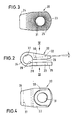
- the clamping device 20 is shown in FIGS. 2 to 4 in Detail shown. It consists of a one-piece Brace with two legs 22, 23, which by a Arc section 24 of reduced material thickness connected are. The facing inside of the both legs 22 and 23 run in the untensioned 2 parallel to each other.
- the one Leg 23, which forms the base leg, instructs a corrugated engagement surface 25 on its outer surface on the also corrugated contact surface 14 the head 13 of the anchoring screw 11 rests, wherein the corrugations are designed such that they interlocking, so that after tightening the clamping screw 16, the clamping device 20th cannot be rotated relative to the head 13.
- the legs 22, 23 include a gap 26 which 2 asymmetrical to that of the arc section 24 enclosed hole 27 runs and into this opens.
- the hole 27 has a cylindrical smooth Inner surface.
- the width of the gap 26 is approximately one Third of the diameter of the hole 27.
- the gap 26 opens only into the lower half of hole 27 one, so that the gap opening exclusively in the area the lower half of the hole cross-section.
- sharp edges 28,29 which are when tightened in the Press in the surface of the side member.
- the upper leg 22 of the clamping device 20 has a depression, the bottom surface of which is a target 30 forms, which under a small Angle of about 5 ° increases towards the outside.
- a target 30 forms, which under a small Angle of about 5 ° increases towards the outside.
- Against the Attack surface 30 presses the head 17 of the clamping screw 16, whereby the leg 22 pivots toward the leg 23 is, so that the surface of attack in the tensioned state 30 runs approximately parallel to the leg 23.
- Through the center of the attack surface 30 and through the Leg 23 passes through a hole 31 through which the Shaft of the clamping screw 16 is inserted.
- the circular arc section 24 is by a Central plane parallel to the leg 23 in divided into two equal halves.
- the gap 26 is located only in the lower half.
- the arch section 24 forms a suspension section in which the clamp deforms when pressed against the leg 22.
- the legs 22 and 23, however, are rigid.
- the spinal fixator offers various options the adjustment and adjustment of the course of the Side member 21. So after loosening the clamping screw 16 the clamping device 20 about the axis of the Turning screw turned and adjusted. in this connection is an adjustment of the side member both in Longitudinal and transverse directions possible to a Adaptation to lordotic and kyphotic curvatures of the To reach the spine. Furthermore, when adjusting also the anchoring screw 11 can still be turned, which also causes a lordotic shift and a pivoting of the side member takes place. By Swiveling the clamping device around the axis of the Height adjustment screw 16 is possible.
Landscapes
- Health & Medical Sciences (AREA)
- Orthopedic Medicine & Surgery (AREA)
- Life Sciences & Earth Sciences (AREA)
- Neurology (AREA)
- Surgery (AREA)
- Molecular Biology (AREA)
- General Health & Medical Sciences (AREA)
- Biomedical Technology (AREA)
- Heart & Thoracic Surgery (AREA)
- Medical Informatics (AREA)
- Nuclear Medicine, Radiotherapy & Molecular Imaging (AREA)
- Animal Behavior & Ethology (AREA)
- Engineering & Computer Science (AREA)
- Public Health (AREA)
- Veterinary Medicine (AREA)
- Surgical Instruments (AREA)
- Steroid Compounds (AREA)
- Saccharide Compounds (AREA)
- Prostheses (AREA)
- Noodles (AREA)
- Distillation Of Fermentation Liquor, Processing Of Alcohols, Vinegar And Beer (AREA)
Claims (7)
- Fixateur de rachis comprenant une vis d'ancrage (11) qui présente une partie filetée (12) et une tête (13), la tête (13) étant dotée d'une surface d'appui (14), un longeron en forme de barre (21) et un dispositif de serrage (20) enserrant le longeron (21), qui est fixé avec une vis de serrage (16) sur la surface d'appui (14) de la tête (13) selon un angle d'orientation réglable, le dispositif de serrage (20) étant conçu sous la forme d'un collier de serrage et présentant deux branches (22, 23) espacées mutuellement, reliées par une section courbe élastique (24),
caractérisé en ce que
la surface d'appui (14) s'étend de manière inclinée par rapport à l'axe longitudinal de la partie filetée (12) et le dispositif de serrage (20) peut être réglé, en tournant autour de l'axe de la vis de serrage (16), dans une position dans laquelle la section courbe (24) et le longeron (21) se trouvent du côté de la surface d'appui (14) qui possède la plus faible distance par rapport à la partie filetée (12). - Fixateur de rachis selon la revendication 1, caractérisé en ce que le dispositif de serrage (20) est agencé d'un seul tenant.
- Fixateur de rachis selon la revendication 1 ou 2, caractérisé en ce que les branches (22, 23) du dispositif de serrage (20) délimitent une fente (26) qui débouche de manière asymétrique dans le trou (27) cerné par la section courbe (24).
- Fixateur de rachis selon la revendication 3, caractérisé en ce que la fente (26) ne débouche que dans une moitié du trou (27) et est divisée en deux moitiés par un plan médian courant parallèlement aux branches (22, 23).
- Fixateur de rachis selon l'une quelconque des revendications 1 à 4, caractérisé en ce que la branche (22) du dispositif de serrage (20) sur laquelle s'applique la tête (17) de la vis de serrage (16) présente une surface d'attaque (30) qui s'étend de manière inclinée par rapport à l'autre branche (23).
- Fixateur de rachis selon l'une quelconque des revendications 1 à 5, caractérisé en ce que la face interne de la section courbe (24) est lisse.
- Fixateur de rachis selon l'une quelconque des revendications 1 à 6, caractérisé en ce que la surface extérieure du longeron (21) entourée par le dispositif de serrage (20) est lisse.
Applications Claiming Priority (2)
| Application Number | Priority Date | Filing Date | Title |
|---|---|---|---|
| DE29712697U | 1997-07-18 | ||
| DE29712697U DE29712697U1 (de) | 1997-07-18 | 1997-07-18 | Wirbelsäulenfixateur |
Publications (3)
| Publication Number | Publication Date |
|---|---|
| EP0891747A2 EP0891747A2 (fr) | 1999-01-20 |
| EP0891747A3 EP0891747A3 (fr) | 1999-06-02 |
| EP0891747B1 true EP0891747B1 (fr) | 2003-09-03 |
Family
ID=8043288
Family Applications (1)
| Application Number | Title | Priority Date | Filing Date |
|---|---|---|---|
| EP98110273A Expired - Lifetime EP0891747B1 (fr) | 1997-07-18 | 1998-06-05 | Fixateur de rachis |
Country Status (4)
| Country | Link |
|---|---|
| EP (1) | EP0891747B1 (fr) |
| AT (1) | ATE248555T1 (fr) |
| DE (2) | DE29712697U1 (fr) |
| ES (1) | ES2206792T3 (fr) |
Families Citing this family (5)
| Publication number | Priority date | Publication date | Assignee | Title |
|---|---|---|---|---|
| FR2784282B1 (fr) | 1998-10-09 | 2001-03-23 | Dimso Sa | Systeme d'osteosynthese rachidienne a rigidite amelioree |
| WO1999055246A1 (fr) * | 1998-04-29 | 1999-11-04 | Dimso (Distribution Medicale Du Sud-Ouest) | Systeme d'osteosynthese rachidienne pour une fixation anterieure |
| DE29923489U1 (de) * | 1999-05-11 | 2000-11-30 | Kluger, Patrick, Dr.med., 89155 Erbach | Schraube zur Anbringung eines Implantats zur Wirbelsäulenstabilisierung und Verlängerungsstab zum Positionieren und Eindrehen der Schraube |
| DE19944120B4 (de) | 1999-09-15 | 2008-08-28 | Ulrich Gmbh & Co. Kg | Knochenschraube zur winkelvariablen Verbindung mit einem Längsträger |
| CN112315569B (zh) * | 2020-11-12 | 2024-09-27 | 上海三友医疗器械股份有限公司 | 脊柱的内固定结构及其内固定系统 |
Family Cites Families (6)
| Publication number | Priority date | Publication date | Assignee | Title |
|---|---|---|---|---|
| US4987892A (en) * | 1989-04-04 | 1991-01-29 | Krag Martin H | Spinal fixation device |
| US5282862A (en) * | 1991-12-03 | 1994-02-01 | Artifex Ltd. | Spinal implant system and a method for installing the implant onto a vertebral column |
| FR2709412B1 (fr) * | 1993-09-01 | 1995-11-24 | Tornier Sa | Vis pour fixateur lombo-sacré. |
| FR2724553B1 (fr) | 1994-09-15 | 1996-12-20 | Tornier Sa | Fixateur externe ou interne destine a la reparation des fractures ou des arthroplasties du squelette |
| FR2731344B1 (fr) * | 1995-03-06 | 1997-08-22 | Dimso Sa | Instrumentation rachidienne notamment pour tige |
| FR2743290B1 (fr) * | 1996-01-10 | 1998-04-03 | Edouard Brice | Dispositif de stabilisation vertebrale |
-
1997
- 1997-07-18 DE DE29712697U patent/DE29712697U1/de not_active Expired - Lifetime
-
1998
- 1998-06-05 AT AT98110273T patent/ATE248555T1/de not_active IP Right Cessation
- 1998-06-05 DE DE59809460T patent/DE59809460D1/de not_active Expired - Lifetime
- 1998-06-05 EP EP98110273A patent/EP0891747B1/fr not_active Expired - Lifetime
- 1998-06-05 ES ES98110273T patent/ES2206792T3/es not_active Expired - Lifetime
Also Published As
| Publication number | Publication date |
|---|---|
| EP0891747A3 (fr) | 1999-06-02 |
| EP0891747A2 (fr) | 1999-01-20 |
| DE59809460D1 (de) | 2003-10-09 |
| ATE248555T1 (de) | 2003-09-15 |
| DE29712697U1 (de) | 1997-09-25 |
| ES2206792T3 (es) | 2004-05-16 |
Similar Documents
| Publication | Publication Date | Title |
|---|---|---|
| DE69726894T2 (de) | Verbindungselement für ein Stabilisierungssystem einer menschlichen Wirbelsäule | |
| DE69920467T2 (de) | Vorrichtung zur wirbelsäulenosteosynthese | |
| DE4303770C1 (de) | Vorrichtung zur Versteifung und/oder Korrektur eines Wirbelsäulenabschnitts | |
| DE69514019T2 (de) | Einrichtung zur Korrektur einer verletzte Wirbel aufweisenden Wirbelsäule | |
| EP0659062B1 (fr) | Implant vertébral postérieur | |
| EP1551320B1 (fr) | Dispositif de fixation orthopedique | |
| DE69729387T2 (de) | Mehrachsige knochenschraubeanordnung | |
| EP0487830B1 (fr) | Implant de correction du rachis humain | |
| DE69737399T2 (de) | Pedikelschrauben-anordnung zur osteosynthese | |
| DE602004003808T2 (de) | Verbindungsvorrichtung für wirbelsäulenosteosynthese | |
| DE69330178T2 (de) | Vorrichtung zum Setzen einer Wirbelsäule | |
| EP1121902B1 (fr) | Vis pédiculaire | |
| DE69529631T2 (de) | Vorrichtung zum Stabilisieren bzw. Komprimieren oder Distrahieren von Abschnitten der Wirbelsäule | |
| DE69025700T2 (de) | Klemme für eine Pedikelschraube | |
| DE69404216T2 (de) | Wirbelfixationsvorrichtung zum Halten der Wirbelsäule | |
| DE69127596T2 (de) | Apparat zur Feststellung der Wirbelsäule | |
| EP1562499B1 (fr) | Dispositif de fixation orthopedique | |
| DE69713684T2 (de) | Apparat zum Festhalten der Wirbelsäule | |
| DE69930391T2 (de) | Winkelverstellbares fixierungssystem für die wirbelsäule | |
| DE69309272T2 (de) | Apparat zur behandlung der wirbelsäule | |
| DE69628916T2 (de) | Hilfsvorrichtung für die wirbelsäulenosteosynthese, insbesondere zum gebrauch mitverbindungsstangen | |
| WO1992003100A1 (fr) | Implant pour dispositif d'osteosynthese, notamment de correction de la colonne vertebrale | |
| EP0689798A1 (fr) | Organe de connexion pour assembler une tige élastique avec un vis vertébrale pédiculaire | |
| EP0509322A1 (fr) | Dispositif de connexion pour la connexion réglable d'un premier élément de construction avec un deuxième, en particulier de tubes ou barres pour un dispositif de fixation | |
| EP1180979A1 (fr) | Dispositif de fixation osseuse dote d'une articulation rotoide |
Legal Events
| Date | Code | Title | Description |
|---|---|---|---|
| PUAI | Public reference made under article 153(3) epc to a published international application that has entered the european phase |
Free format text: ORIGINAL CODE: 0009012 |
|
| AK | Designated contracting states |
Kind code of ref document: A2 Designated state(s): AT BE CH DE DK ES FI FR GB GR IE IT LI NL PT SE |
|
| AX | Request for extension of the european patent |
Free format text: AL;LT;LV;MK;RO;SI |
|
| PUAL | Search report despatched |
Free format text: ORIGINAL CODE: 0009013 |
|
| AK | Designated contracting states |
Kind code of ref document: A3 Designated state(s): AT BE CH CY DE DK ES FI FR GB GR IE IT LI LU MC NL PT SE |
|
| AX | Request for extension of the european patent |
Free format text: AL;LT;LV;MK;RO;SI |
|
| 17P | Request for examination filed |
Effective date: 19991125 |
|
| AKX | Designation fees paid |
Free format text: AT BE CH DE DK ES FI FR GB GR IE IT LI NL PT SE |
|
| 17Q | First examination report despatched |
Effective date: 20020221 |
|
| GRAH | Despatch of communication of intention to grant a patent |
Free format text: ORIGINAL CODE: EPIDOS IGRA |
|
| GRAH | Despatch of communication of intention to grant a patent |
Free format text: ORIGINAL CODE: EPIDOS IGRA |
|
| RAP1 | Party data changed (applicant data changed or rights of an application transferred) |
Owner name: TORNIER VERTRIEBS- UND BERATUNGSGESELLSCHAFT FUER |
|
| GRAA | (expected) grant |
Free format text: ORIGINAL CODE: 0009210 |
|
| AK | Designated contracting states |
Kind code of ref document: B1 Designated state(s): AT BE CH DE DK ES FI FR GB GR IE IT LI NL PT SE |
|
| PG25 | Lapsed in a contracting state [announced via postgrant information from national office to epo] |
Ref country code: IE Free format text: LAPSE BECAUSE OF FAILURE TO SUBMIT A TRANSLATION OF THE DESCRIPTION OR TO PAY THE FEE WITHIN THE PRESCRIBED TIME-LIMIT Effective date: 20030903 Ref country code: GB Free format text: LAPSE BECAUSE OF FAILURE TO SUBMIT A TRANSLATION OF THE DESCRIPTION OR TO PAY THE FEE WITHIN THE PRESCRIBED TIME-LIMIT Effective date: 20030903 Ref country code: FI Free format text: LAPSE BECAUSE OF FAILURE TO SUBMIT A TRANSLATION OF THE DESCRIPTION OR TO PAY THE FEE WITHIN THE PRESCRIBED TIME-LIMIT Effective date: 20030903 |
|
| REG | Reference to a national code |
Ref country code: GB Ref legal event code: FG4D Free format text: NOT ENGLISH |
|
| REG | Reference to a national code |
Ref country code: CH Ref legal event code: EP |
|
| REF | Corresponds to: |
Ref document number: 59809460 Country of ref document: DE Date of ref document: 20031009 Kind code of ref document: P |
|
| REG | Reference to a national code |
Ref country code: IE Ref legal event code: FG4D Free format text: GERMAN |
|
| REG | Reference to a national code |
Ref country code: CH Ref legal event code: NV Representative=s name: INTERPAT LAW AG |
|
| PG25 | Lapsed in a contracting state [announced via postgrant information from national office to epo] |
Ref country code: SE Free format text: LAPSE BECAUSE OF FAILURE TO SUBMIT A TRANSLATION OF THE DESCRIPTION OR TO PAY THE FEE WITHIN THE PRESCRIBED TIME-LIMIT Effective date: 20031203 Ref country code: GR Free format text: LAPSE BECAUSE OF FAILURE TO SUBMIT A TRANSLATION OF THE DESCRIPTION OR TO PAY THE FEE WITHIN THE PRESCRIBED TIME-LIMIT Effective date: 20031203 Ref country code: DK Free format text: LAPSE BECAUSE OF FAILURE TO SUBMIT A TRANSLATION OF THE DESCRIPTION OR TO PAY THE FEE WITHIN THE PRESCRIBED TIME-LIMIT Effective date: 20031203 |
|
| PG25 | Lapsed in a contracting state [announced via postgrant information from national office to epo] |
Ref country code: PT Free format text: LAPSE BECAUSE OF FAILURE TO SUBMIT A TRANSLATION OF THE DESCRIPTION OR TO PAY THE FEE WITHIN THE PRESCRIBED TIME-LIMIT Effective date: 20040203 |
|
| GBV | Gb: ep patent (uk) treated as always having been void in accordance with gb section 77(7)/1977 [no translation filed] |
Effective date: 20030903 |
|
| REG | Reference to a national code |
Ref country code: IE Ref legal event code: FD4D |
|
| REG | Reference to a national code |
Ref country code: ES Ref legal event code: FG2A Ref document number: 2206792 Country of ref document: ES Kind code of ref document: T3 |
|
| PG25 | Lapsed in a contracting state [announced via postgrant information from national office to epo] |
Ref country code: AT Free format text: LAPSE BECAUSE OF NON-PAYMENT OF DUE FEES Effective date: 20040605 |
|
| ET | Fr: translation filed | ||
| PG25 | Lapsed in a contracting state [announced via postgrant information from national office to epo] |
Ref country code: BE Free format text: LAPSE BECAUSE OF NON-PAYMENT OF DUE FEES Effective date: 20040630 |
|
| PLBE | No opposition filed within time limit |
Free format text: ORIGINAL CODE: 0009261 |
|
| STAA | Information on the status of an ep patent application or granted ep patent |
Free format text: STATUS: NO OPPOSITION FILED WITHIN TIME LIMIT |
|
| 26N | No opposition filed |
Effective date: 20040604 |
|
| BERE | Be: lapsed |
Owner name: *TORNIER VERTRIEBS- UND BERATUNGSGESELLSCHAFT FUR Effective date: 20040630 |
|
| PGFP | Annual fee paid to national office [announced via postgrant information from national office to epo] |
Ref country code: ES Payment date: 20070725 Year of fee payment: 10 |
|
| REG | Reference to a national code |
Ref country code: CH Ref legal event code: PCAR Free format text: ISLER & PEDRAZZINI AG;POSTFACH 1772;8027 ZUERICH (CH) |
|
| PGFP | Annual fee paid to national office [announced via postgrant information from national office to epo] |
Ref country code: IT Payment date: 20070627 Year of fee payment: 10 |
|
| PGFP | Annual fee paid to national office [announced via postgrant information from national office to epo] |
Ref country code: NL Payment date: 20070717 Year of fee payment: 10 |
|
| NLV4 | Nl: lapsed or anulled due to non-payment of the annual fee |
Effective date: 20090101 |
|
| PG25 | Lapsed in a contracting state [announced via postgrant information from national office to epo] |
Ref country code: NL Free format text: LAPSE BECAUSE OF NON-PAYMENT OF DUE FEES Effective date: 20090101 |
|
| REG | Reference to a national code |
Ref country code: ES Ref legal event code: FD2A Effective date: 20080606 |
|
| PG25 | Lapsed in a contracting state [announced via postgrant information from national office to epo] |
Ref country code: IT Free format text: LAPSE BECAUSE OF NON-PAYMENT OF DUE FEES Effective date: 20080605 |
|
| PG25 | Lapsed in a contracting state [announced via postgrant information from national office to epo] |
Ref country code: ES Free format text: LAPSE BECAUSE OF NON-PAYMENT OF DUE FEES Effective date: 20080606 |
|
| PGFP | Annual fee paid to national office [announced via postgrant information from national office to epo] |
Ref country code: FR Payment date: 20100623 Year of fee payment: 13 |
|
| PGFP | Annual fee paid to national office [announced via postgrant information from national office to epo] |
Ref country code: CH Payment date: 20100615 Year of fee payment: 13 |
|
| PGFP | Annual fee paid to national office [announced via postgrant information from national office to epo] |
Ref country code: DE Payment date: 20100614 Year of fee payment: 13 |
|
| REG | Reference to a national code |
Ref country code: CH Ref legal event code: PL |
|
| REG | Reference to a national code |
Ref country code: FR Ref legal event code: ST Effective date: 20120229 |
|
| REG | Reference to a national code |
Ref country code: DE Ref legal event code: R119 Ref document number: 59809460 Country of ref document: DE Effective date: 20120103 |
|
| PG25 | Lapsed in a contracting state [announced via postgrant information from national office to epo] |
Ref country code: DE Free format text: LAPSE BECAUSE OF NON-PAYMENT OF DUE FEES Effective date: 20120103 Ref country code: LI Free format text: LAPSE BECAUSE OF NON-PAYMENT OF DUE FEES Effective date: 20110630 Ref country code: FR Free format text: LAPSE BECAUSE OF NON-PAYMENT OF DUE FEES Effective date: 20110630 Ref country code: CH Free format text: LAPSE BECAUSE OF NON-PAYMENT OF DUE FEES Effective date: 20110630 |