EP0891799B1 - Verfahren und Anlage zur Entölung fettiger Substanzen - Google Patents
Verfahren und Anlage zur Entölung fettiger Substanzen Download PDFInfo
- Publication number
- EP0891799B1 EP0891799B1 EP97112270A EP97112270A EP0891799B1 EP 0891799 B1 EP0891799 B1 EP 0891799B1 EP 97112270 A EP97112270 A EP 97112270A EP 97112270 A EP97112270 A EP 97112270A EP 0891799 B1 EP0891799 B1 EP 0891799B1
- Authority
- EP
- European Patent Office
- Prior art keywords
- reactor
- oil
- heating
- installation
- jacket tube
- Prior art date
- Legal status (The legal status is an assumption and is not a legal conclusion. Google has not performed a legal analysis and makes no representation as to the accuracy of the status listed.)
- Expired - Lifetime
Links
Images
Classifications
-
- C—CHEMISTRY; METALLURGY
- C10—PETROLEUM, GAS OR COKE INDUSTRIES; TECHNICAL GASES CONTAINING CARBON MONOXIDE; FUELS; LUBRICANTS; PEAT
- C10J—PRODUCTION OF PRODUCER GAS, WATER-GAS, SYNTHESIS GAS FROM SOLID CARBONACEOUS MATERIAL, OR MIXTURES CONTAINING THESE GASES; CARBURETTING AIR OR OTHER GASES
- C10J3/00—Production of combustible gases containing carbon monoxide from solid carbonaceous fuels
- C10J3/007—Screw type gasifiers
-
- B—PERFORMING OPERATIONS; TRANSPORTING
- B09—DISPOSAL OF SOLID WASTE; RECLAMATION OF CONTAMINATED SOIL
- B09C—RECLAMATION OF CONTAMINATED SOIL
- B09C1/00—Reclamation of contaminated soil
- B09C1/06—Reclamation of contaminated soil thermally
-
- C—CHEMISTRY; METALLURGY
- C10—PETROLEUM, GAS OR COKE INDUSTRIES; TECHNICAL GASES CONTAINING CARBON MONOXIDE; FUELS; LUBRICANTS; PEAT
- C10B—DESTRUCTIVE DISTILLATION OF CARBONACEOUS MATERIALS FOR PRODUCTION OF GAS, COKE, TAR, OR SIMILAR MATERIALS
- C10B7/00—Coke ovens with mechanical conveying means for the raw material inside the oven
-
- C—CHEMISTRY; METALLURGY
- C10—PETROLEUM, GAS OR COKE INDUSTRIES; TECHNICAL GASES CONTAINING CARBON MONOXIDE; FUELS; LUBRICANTS; PEAT
- C10B—DESTRUCTIVE DISTILLATION OF CARBONACEOUS MATERIALS FOR PRODUCTION OF GAS, COKE, TAR, OR SIMILAR MATERIALS
- C10B7/00—Coke ovens with mechanical conveying means for the raw material inside the oven
- C10B7/10—Coke ovens with mechanical conveying means for the raw material inside the oven with conveyor-screws
-
- C—CHEMISTRY; METALLURGY
- C10—PETROLEUM, GAS OR COKE INDUSTRIES; TECHNICAL GASES CONTAINING CARBON MONOXIDE; FUELS; LUBRICANTS; PEAT
- C10J—PRODUCTION OF PRODUCER GAS, WATER-GAS, SYNTHESIS GAS FROM SOLID CARBONACEOUS MATERIAL, OR MIXTURES CONTAINING THESE GASES; CARBURETTING AIR OR OTHER GASES
- C10J3/00—Production of combustible gases containing carbon monoxide from solid carbonaceous fuels
- C10J3/72—Other features
- C10J3/74—Construction of shells or jackets
-
- F—MECHANICAL ENGINEERING; LIGHTING; HEATING; WEAPONS; BLASTING
- F26—DRYING
- F26B—DRYING SOLID MATERIALS OR OBJECTS BY REMOVING LIQUID THEREFROM
- F26B17/00—Machines or apparatus for drying materials in loose, plastic, or fluidised form, e.g. granules, staple fibres, with progressive movement
- F26B17/18—Machines or apparatus for drying materials in loose, plastic, or fluidised form, e.g. granules, staple fibres, with progressive movement with movement performed by rotating helical blades or other rotary conveyors which may be heated moving materials in stationary chambers, e.g. troughs
- F26B17/20—Machines or apparatus for drying materials in loose, plastic, or fluidised form, e.g. granules, staple fibres, with progressive movement with movement performed by rotating helical blades or other rotary conveyors which may be heated moving materials in stationary chambers, e.g. troughs the axis of rotation being horizontal or slightly inclined
-
- F—MECHANICAL ENGINEERING; LIGHTING; HEATING; WEAPONS; BLASTING
- F26—DRYING
- F26B—DRYING SOLID MATERIALS OR OBJECTS BY REMOVING LIQUID THEREFROM
- F26B23/00—Heating arrangements
- F26B23/02—Heating arrangements using combustion heating
- F26B23/022—Heating arrangements using combustion heating incinerating volatiles in the dryer exhaust gases, the produced hot gases being wholly, partly or not recycled into the drying enclosure
-
- F—MECHANICAL ENGINEERING; LIGHTING; HEATING; WEAPONS; BLASTING
- F27—FURNACES; KILNS; OVENS; RETORTS
- F27B—FURNACES, KILNS, OVENS OR RETORTS IN GENERAL; OPEN SINTERING OR LIKE APPARATUS
- F27B7/00—Rotary-drum furnaces, i.e. horizontal or slightly inclined
- F27B7/20—Details, accessories or equipment specially adapted for rotary-drum furnaces
-
- C—CHEMISTRY; METALLURGY
- C10—PETROLEUM, GAS OR COKE INDUSTRIES; TECHNICAL GASES CONTAINING CARBON MONOXIDE; FUELS; LUBRICANTS; PEAT
- C10J—PRODUCTION OF PRODUCER GAS, WATER-GAS, SYNTHESIS GAS FROM SOLID CARBONACEOUS MATERIAL, OR MIXTURES CONTAINING THESE GASES; CARBURETTING AIR OR OTHER GASES
- C10J2300/00—Details of gasification processes
- C10J2300/12—Heating the gasifier
- C10J2300/1246—Heating the gasifier by external or indirect heating
-
- F—MECHANICAL ENGINEERING; LIGHTING; HEATING; WEAPONS; BLASTING
- F27—FURNACES; KILNS; OVENS; RETORTS
- F27B—FURNACES, KILNS, OVENS OR RETORTS IN GENERAL; OPEN SINTERING OR LIKE APPARATUS
- F27B7/00—Rotary-drum furnaces, i.e. horizontal or slightly inclined
- F27B7/02—Rotary-drum furnaces, i.e. horizontal or slightly inclined of multiple-chamber or multiple-drum type
- F27B7/04—Rotary-drum furnaces, i.e. horizontal or slightly inclined of multiple-chamber or multiple-drum type with longitudinal divisions
- F27B2007/046—Radial partitions
- F27B2007/048—Radial partitions defining an helical chamber
Definitions
- the invention relates to a method and a system for Deoiling of greasy substances such as Mill scale, shavings, Sludges and oil-contaminated minerals according to the generic term of the first claim.
- DE-A-38 16 493 describes a method for the disassembly of a Starting product, preferably mill scale, in his Components described.
- the starting product subjected to a thermal treatment. It is in metallic and non-metallic solids as well as in vapor or gaseous media disassembled.
- the Starting product is indirectly heated so that it does not comes into contact with the heat-carrying media.
- outgassed components from the Mill scale is except for a residual amount of gas in one transferred liquid phase.
- the residual gas is extracted and burned or processed.
- the liquefied component is filtered for residual oil in a deoiling system.
- the Oil is cleaned and reused.
- the metallic and non-metallic solids are by means of mechanical and / or electromagnetic separation processes split into metallic and non-metallic fractions.
- Another method and apparatus for Processing of contaminated waste materials e.g. Dusts, sludges, mill scale, old sand, etc. Describes DE-A-41 09 136.
- a gas By introducing a gas into a Bulk bed creates a fluidized bed that partly consists of bulk material and heated from above becomes.
- the heating intensity is controllable, so that on the one hand the solid temperature and on the other hand the located in the one above the fluidized bed Gas space prevailing gas temperature can be influenced.
- the bulk material is one to produce the fluidized bed Fluidized bed furnace fed. All known solutions are structurally complex and costly.
- the object of the invention is a method and associated system for the deoiling of greasy substances develop that through a few simple process steps distinguished with the associated system simple structure and reliable Working with a long service life guaranteed and works with minimal energy consumption.
- This task is characterized by the characteristics of the first and fifth claim and the further features in their subclaims solved.
- This will be procedural the greasy substances to be de-oiled, e.g. Mill scale, shavings, slurries and oil-contaminated minerals by indirect heating of a thermal Treated by the thermal Treatment resulting gas derived.
- the substance to be oiled is transferred via a conveyor fed to a reactor.
- the Feed to the reactor takes place with starting substances an increased level of moisture during delivery heating to approx. 100 ° C to 150 ° C, which causes this is drained. After the removal of the resulting This becomes water vapor by cooling into the liquid Phase transferred.
- the starting substances to be de-oiled are subsequently heated indirectly from the outside Reactor fed and in this under one continuous feed and circulation movement at one Temperature in the range of 280 ° C to 400 ° C heated.
- This temperature prevailing in the reactor is derived from the Substance the oils and fats in the gaseous phase transferred.
- These oil and fat vapors are extracted and can, for example, for indirect heating of the Reactor fed to a combustion and heating unit be, then the further heating of the reactor either additionally or exclusively with the as Waste product separated oil and fat vapors takes place.
- the initial heating can be reduced to the extent be how the heating power by using the oil and Fat vapors supplied the combustion and heating unit increases.
- the exhaust gases as start-up energy an industrial facility, particularly the one in used in a rolling mill or blast furnace become.
- the feed takes place the amount of energy for indirect heating by the industrial facility and the supply of energy for indirect heating by burning the recovered oil-gas phase depending on the im Reactor existing temperature over a corresponding Regulation or control device.
- the throughput of the starting substance to be oiled is in Depends on the amount of oil to be de-oiled Substance set. For de-oiling mill scale for example, it should be in the 3-5 ton range Hour. The cycle time should be when de-oiling of mill scale at least 20 minutes. The for the respective starting substance for reliable deoiling required lead times can be determined by previous Experiments can be easily identified.
- the system for deoiling greasy substances such as Mill scale, shavings, slurries and oil-contaminated minerals is known with a feeder for the greasy substances and a derivation for the degreased Substances, as well as equipped with a heating device.
- a reactor Continuous furnace
- at least one conveyor for Generation of a continuous or discontinuous Feed and circulation movement arranged.
- a heating medium for example the exhaust gases of an industrial Equipment that is flowed through and heated and thus for serves indirect heating of the interior of the reactor.
- the supply of the oil and fat-containing starting substances is at one end and the derivative for the degreased Substances arranged at the other end of the reactor.
- a suction device for the oil and fat vapors generated by the heating provided with one on the outer reactor wall arranged, used to generate the heating medium, Combustion and heating unit is connected.
- the reactor can advantageously in a defined Be inclined.
- the suction device is located then advantageously at the end of the reactor, which is higher and where the exhaustion is arranged.
- the supply line for the heating medium in the form of the exhaust gases preferably located at the end of the reactor which is the supply for the starting substance located.
- the exhaust gases are preferably discharged at the opposite end of the reactor.
- the conveyor is in the form of one or more transport screws trained because with these a reliable Transport and circulation movement of the starting substance is achieved.
- Each transport screw is in a screw casing tube guided.
- the outer diameter of the respective screw conveyor is the inside diameter of the screw jacket tube adapted so that a reliable transport and Circulation movement takes place and thereby on the inner wall of the If possible, there is no deposition of the Starting substance can take place.
- To discharge the Oil and grease vapors generated show the screw jacketed pipes upward openings. On the Openings are above the profile for further derivation Screw shell tube arranged that they with their Outside edges fit tightly on the one hand and on the other hand between the screw casing tube and the profile Space arises.
- the profiles are connected to the exhaust pipes, which the oil and fat vapors over the Extraction to the combustion and heating unit leads. Furthermore, the system points to the feeder one of the drainage of the starting substance serving heating unit.
- All screw jacketed pipes a system are from the outer jacket of the Raktors enclosed.
- the space between the screw jacketed pipes and the outer jacket is from the heating medium flows through and is used for indirect heating of the Starting material, which with the screw conveyor the screw jacketed pipes are transported.
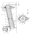
- the starting substance SA to be de-oiled passes through a Feed 1 in the reactor 2.
- the feeder 1 is one Assigned heating unit 3, in which the starting substance to a temperature in the range of approx. 100 ° C to 150 ° C is heated. Then at the feeder 1 also a drain 4 for the water vapor produced provided, which then goes into the liquid phase is transferred.
- the starting substance is SA moved forward by a screw conveyor 5 and circulated and to a temperature in the range of 280 ° C. heated to 400 ° C. Due to the high temperature oils and fats present in the starting substance SA transferred the gaseous state of matter. With a Suction device 6, the resulting oil and Fat vapors are suctioned off and arranged on the reactor 2 Combustion and heating unit 7 supplied. At the other At the end the degreased substances SE over a Exhaust 8 removed.
- the reactor 2 has an outer wall W, in which the transport screw 5 in the associated screw jacket tube M is arranged. Between the outer wall of the Screw jacket tube M and the outer wall W becomes a Boiler room 10 formed. At one end of the rector 2 is the feed line 9 for the heating medium Boiler room 10 and at the other end the derivative 11 for that Heating medium. In the illustrated embodiment according to 1 is the feed line 9 at the end of the reactor 2 arranged, on which the feed 1 for the Starting substance SA is located. At the opposite end of the reactor 2 is the derivative 11 for the Heating medium, the discharge 8 for the deoiled substance SE and the suction device 6. For reliable discharge an overhead opening 12 is provided. Instead of one Opening can also be multiple openings or one Longitudinal slot are introduced.
- the U-profile 13 lies with both ends its parallel legs close to the screw casing tube M on. Between the connecting web of the parallel legs and the screw casing tube M is provided with a clearance, the unhindered flow of oil and gas vapors guaranteed.
- a further opening 14 is in the profile 13 provided, on which the exhaust pipe 20 is sealed is attached, which is the connection to the suction device 6 manufactures. Since the inner wall of the screw jacketed pipe M is exposed to high wear, A replaceable inner bushing 16 can be provided become. This also has an overhead Longitudinal slot on the under the longitudinal slot in Snail jacketed pipe. If the inner socket is worn out, can be easily replaced.
- the boiler room 10 are preferably used as start-up energy the exhaust gases from an industrial facility, e.g. a blast furnace or a rolling mill. This Pushing energy can be reduced to the extent that additional energy by burning the generated Oil and fat vapors are made available. Standing on Place of installation of the plant no industrial exhaust gases for the Push-off energy available can also be another Type of heating z. B. used an additional oil burner become.
- Each screw jacket tube M has a feed opening at one end and a discharge opening at the other end.
- the downstream screw casing tube M is hermetically sealed at its feed opening with the discharge opening of the upstream screw casing pipe M.
- the first screw jacket pipe M is also connected hermetically with its feed opening to the feed 1 of the starting substance SA and the screw jacket pipe M arranged last in series with its discharge opening with the discharge 8 for the deoiled substance SE.
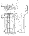
- FIG. 2 A variant in which three transport screws 5.1, 5.2, 5.3 are arranged one above the other and in a row in an outer wall W of the reactor 2 is shown in FIG. 2.
- Each screw conveyor 5.1, 5.2, 5.3 is located in a screw jacket tube M1, M2, M3, and is supported at its ends on the two side surfaces of the outer wall W of the reactor 2. All three screw conveyors 5.1, 5.2, 5.3 are driven by a common drive unit A.
- the sectional view in FIG. 2a shows the longitudinal section through the system. In the drawing on the left at the top of the reactor 2 is the feed 1 for the starting substances SA to be de-oiled. In this case, no additional heating device 7 is provided for dewatering (for starting substances with a relatively low degree of moisture).
- the tubular feed 1 for the starting substance S is hermetically sealed to the feed opening 17.1 in the first screw casing tube M1 of the first transport screw 5.1.
- the discharge opening 18.1 of the first screw casing tube M1 is hermetically sealed to the feed opening 17.2 of the second screw casing pipe M2 via a first connecting pipe 19.1 and the discharge opening 18.2 of the second screw casing pipe M2 is connected to the supply opening 17.3 of the third screw casing pipe M3 via a second connecting pipe 19.2.
- the discharge 8 for the deoiled substance SE also hermetically adjoins the discharge opening 18.3 of the third screw jacket tube M3.
- the profiles 13, to which the exhaust pipes 20 are connected, are located above each screw jacket pipe M1, M2, M3. In this case, exhaust pipes 20 are connected to each screw jacket pipe (profile) at two positions.
- the exhaust gas lines 20 lead to a common suction 6 and further to an oil condenser 21.
- a cleaning opening 22 can be provided for better cleaning of the interior of the reactor.
- a side view of the system acc. Fig. 2a is shown in Fig. 2b.
- the supply line 9 is located on the rear wall of the outer wall W and the discharge line 11 for the heating medium is located on the front wall.
- the exhaust pipes 20 are passed in front of the screw jacketed pipes M1-M3.
- the starting substance SA enters through the feed 1 in the first screw conveyor 5.1 and is in the direction of the arrow up to derivative 8 on the third screw conveyor 5.3 emotional.
- the heating medium flows through the boiler room 10 and heats the screw jacketed pipes M1-M3 and thus indirectly the starting substance SA.
- the one in the source substance SA oils and fats contained during their passage heated and into the gaseous phase transferred.
- the screw casing tubes M1 to M3 and profiles 13 arranged openings 12 and 14 the oil and fat vapors get through it attached exhaust pipes 20 to the suction device 6 and on to the oil condenser 21.
- the oil and Fat vapors are converted into the liquid phase.
- the resulting Oil condensate can be stored and reused or an internal combustion engine.
- the filter can be cleaned with a filter Oil condensate from any floating particles.
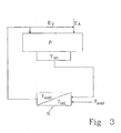
- FIG. 3 shows a possibility of controlling and regulating the plant as a function of the temperatures present in the reactor.
- the supply of the output energy E A in the current process P is carried out as a function of the process temperature T, and to the input as a guidance variable to the control unit S set temperature T.
- Additional process energy E Z which is obtained from the combustion of the extracted gases, can also be fed to the process P as required.
- Another control not shown, influences the feed and circulating movement of the screw conveyors. Depending on the process, this can run continuously or discontinuously. If necessary, after a phase of the feed movement, there can also be a standstill with a defined dwell time or a backward movement of the transport screws and then a forward movement again.
- the solution according to the invention is compared to conventional solutions a simple and inexpensive Variant for deoiling greasy starting substances created. Due to the possibility of using the oil and Grease vapors for heating the system can necessary energy consumption reduced to a minimum become. The arrangement of several transport screws next to and / or one above the other reduces the space required by the Plant essential.
Landscapes
- Chemical & Material Sciences (AREA)
- Engineering & Computer Science (AREA)
- Organic Chemistry (AREA)
- Oil, Petroleum & Natural Gas (AREA)
- General Engineering & Computer Science (AREA)
- Mechanical Engineering (AREA)
- Combustion & Propulsion (AREA)
- Life Sciences & Earth Sciences (AREA)
- Materials Engineering (AREA)
- Sustainable Development (AREA)
- Physics & Mathematics (AREA)
- Thermal Sciences (AREA)
- Soil Sciences (AREA)
- Environmental & Geological Engineering (AREA)
- Physical Or Chemical Processes And Apparatus (AREA)
- Processing Of Solid Wastes (AREA)
Description
- Fig. 1:
- Prinzipdarstellung einer Anlage unter Anwendung einer Transportschnecke
- Fig. 1a:
- Schnittdarstellung entlang der Linie A-A gem. Fig. 1
- Fig. 2a:
- Prinzipdarstellung einer Anlage unter Anwendung von drei Transportschnecken im Längsschnitt
- Fig. 2b:
- Seitenansicht gem. Fig. 2a
- Fig. 2c:
- Draufsicht gem. Fig. 2a
- Fig. 3:
- Steuer- bzw. Regelprozeß
Eine Variante, bei welcher drei Transportschnecken 5.1, 5.2, 5.3 übereinander und in Reihe in einer Außenwandung W des Reaktors 2 angeordnet sind wird in Fig. 2 gezeigt. Jede Transportschnecke 5.1, 5.2, 5.3 befindet sich in einem Schneckenmantelrohr M1, M2, M3, und ist an ihren Enden an den beiden Seitenflächen der Außenwandung W des Reaktors 2 gelagert. Der Antrieb aller drei Transportschnecken 5.1, 5.2, 5.3 erfolgt über eine gemeinsame Antriebseinheit A. Die Schnittdarstellung in Fig. 2a zeigt den Längsschnitt durch die Anlage. In der Zeichnung links befindet sich oben am Reaktor 2 die Zuführung 1 für die zu entölenden Ausgangssubstanzen SA. Dabei ist in diesem Fall keine zusätzliche Heizeinrichtung 7 zur Entwässerung vorgesehen (für Ausgangssubstanzen mit relativ geringem Feuchtigkeitsgrad). Die rohrförmige Zuführung 1 für die Ausgangssubstanz S ist hermetisch dicht mit dem Zuführdurchbruch 17.1 im ersten Schneckenmantelrohr M1 der ersten Transportschnecke 5.1 verbunden. Der Ableitdurchbruch 18.1 des ersten Schneckenmantelrohres M1 ist mit dem Zuführdurchbruch 17.2 des zweiten Schneckenmantelrohres M2 über ein erstes Verbindungsrohr 19.1 und der Ableitdurchbruch 18.2 des zweiten Schneckenmantelrohres M2 ist mit dem Zuführdurchbruch 17.3 des dritten Schneckenmantelrohres M3 über ein zweites Verbindungsrohr 19.2 hermetisch dicht verbunden. An den Ableitdurchbruch 18.3 des dritten Schneckenmantelrohres M3 schließt sich ebenfalls hermetisch dicht die Abführung 8 für die entölte Substanz SE an. Über jedem Schneckenmantelrohr M1, M2, M3 befinden sich die Profile 13, an welche die Abgasleitungen 20 angeschlossen werden. In diesem Fall sind an jedem Schneckenmantelrohr (Profil) an zwei Positionen Abgasleitungen 20 angeschlossen. Die Abgasleitungen 20 führen zu einer gemeinsamen Absaugung 6 und weiter zu einem Ölkondensator 21. Zur besseren Reinigung des Innenraumes des Reaktors kann, wie angedeutet dargestellt, eine Reinigungsöffnung 22 vorgesehen werden. Eine Seitendarstellung der Anlage gem. Fig. 2a wird in Fig. 2b dargestellt. An der Rückwand der Außenwandung W befindet sich dabei die Zuleitung 9 und an der Vorderwand die Ableitung 11 für das Heizmedium. Die Abgasleitungen 20 werden vor den Schneckenmantelrohren M1-M3 vorbeigeführt.
Claims (15)
- Verfahren zur Entölung fettiger Substanzen wie z.B. Walzzunder, Späne, Schlämme und ölkontaminierte Mineralien, wobei die Ausgangssubstanz (SA) durch indirekte Beheizung einer thermischen Behandlung unterzogen wird und die durch die thermische Behandlung entstehenden Gas- und Fettdämpfe abgeleitet werden, wobei die zu entölenden Ausgangssubstanzen (SA) einem Reaktor (2) zugeführt werden, in dem bei einer Temperatur im Bereich von 280°C bis 400°C eine Vorschub- und Umwälzbewegung der zu entölenden Ausgangssubstanz (SA) erzeugt wird,
während der Zuführung zum Reaktor (2) die Ausgangssubstanzen (SA) durch eine Erwärmung auf 100°C bis 150°C entwässert werden,
die durch eine kontinuierliche, diskontinuierliche oder reversierende Vorschub- und Umwälzbewegung und die im Reaktor (2) herrschende Temperatur aus der Ausgangssubstanz (SA) abgespalteten und in die gasförmige Phase überführten Öle und Fette abgesaugt und anschließend die Öl- und Fettdämpfe zur indirekten Beheizung des Reaktors (2) einer Verbrennungs- und Heizeinheit (7) zugeleitet werden, wobei die weitere Beheizung des Reaktors (2) zusätzlich oder ausschließlich mit den abgeschiedenen Öl- und Fettdämpfen erfolgt. - Verfahren nach Anspruch 1, dadurch gekennzeichnet, dass zur anfänglichen indirekten Erwärmung des Reaktors (2) als Anschubenergie die Abgase einer industriellen Einrichtung, insbesondere die in einem Walzwerk bzw. Hochofen anfallenden Abgase, genutzt werden.
- Verfahren nach Anspruch 1 oder 2, dadurch gekennzeichnet, dass nach Anlaufen des Entölungsvorganges die Zufuhr der Energiemenge für die indirekte Beheizung durch die industrielle Einrichtung und die Zufuhr der Energiemenge für die indirekte Beheizung durch die Verbrennung der gewonnenen Öl-Gas-Phase in Abhängigkeit von der im Reaktor (2) vorhandenen Temperatur regel- bzw. steuerbar sind.
- Verfahren nach einem der Ansprüche 1 bis 3, dadurch gekennzeichnet, dass die notwendige Durchlaufzeit entsprechend der Zusammensetzung der Ausgangssubstanz (SA) und der geforderten Bedingungen für die Weiterverwendung der entölten Substanz (SE) festgelegt und vorzugsweise durch Referenzversuche ermittelt wird.
- Anlage zur Entölung fettiger Substanzen wie z.B. Walzzunder, Späne, Schlämme und ölkontaminierte Mineralien mit einer Zuführung (1) für die fettigen Ausgangssubstanzen (SA) und einer Abführung (8) für die entfetteten Substanzen (SE), sowie mit einer indirekten Beheizung, wobei in der Außenwandung (W) eines Reaktors (2) mindestens eine Fördereinrichtung zur Erzeugung einer Vorschub- und Umwälzbewegung der. fettigen Ausgangssubstanzen (SA) angeordnet ist,
die gesamte, eine kontinuierliche, diskontinuierliche oder reversierende Vorschub- und Umwälzbewegung erzeugende Fördereinrichtung von einem Gehäuse ummantelt ist und der Raum zwischen der Außenwandung (W) des Reaktors (2) und dem Gehäuse der Fördereinrichtung von einem Heizmedium durchströmt wird,
am Reaktor (2) eine Absaugeinrichtung (6) für die durch die Beheizung entstandenen Öl- und Fettdämpfe angeordnet ist, die mit einer an der äußeren Reaktorwandung (W) angeordneten, zur Erzeugung des Heizmediums dienenden, Verbrennungs- und Heizeinheit (7) verbunden ist und
an der Zuführung (1) eine der Entwässerung der Ausgangssubstanz (SA) dienende Heizeinheit (3) angeordnet ist. - Anlage nach Anspruch 5, dadurch gekennzeichnet, dass mehrere jeweils von einem Gehäuse ummantelte Fördereinrichtungen in Reihe oder parallel neben- und/oder übereinander im Reaktor (2) angeordnet sind, wobei jede Fördereinrichtung im Gehäuse an einem Ende einen Zuführdurchbruch und am anderen Ende einen Ableitdurchbruch aufweist.
- Anlage nach Anspruch 5 und 6, dadurch gekennzeichnet, dass bei der Reihenanordnung die jeweils nachgeordnete Fördereinrichtung an ihrem zuführdurchbruch mit dem Ableitdurchbruch der vorgelagerten Fördereinrichtung sowie die erste Fördereinrichtung mit ihrem Zuführdurchbruch mit der Zuführung (1) für die Ausgangssubstanz (SE) und die in Reihe zuletzt angeordnete Fördereinrichtung mit ihrem Ableitdurchbruch mit der Abführung (8) für die entölte Substanz (SE) hermetisch dicht verbunden sind.
- Anlage nach einem der Ansprüche 5 bis 7, dadurch gekennzeichnet, dass die Fördereinrichtung als Transportschnecke (5, 5.1, 5.2, 5.3) ausgebildet ist, die von einem als Gehäuse dienenden Schneckenmantelrohr (M, M1, M2, M3) umgeben wird.
- Anlage nach Anspruch 8, dadurch gekennzeichnet, dass zur zuverlässigen Ableitung der Öl- und Gasdämpfe im Schneckenmantelrohr (M, M1, M2, M3) mindestens eine oben liegende Öffnung (12) vorgesehen ist, die mit der Absaugeinrichtung (6) über eine Abgasleitung (20) verbunden ist und dass das Schneckenmantelrohr (M, M1, M2, M3) über seine gesamte Länge eine oder mehrere Öffnungen (12) aufweist, die mit einer profilartigen Abdeckung (14) versehen sind, wobei zur Ableitung der Öl- und Fettdämpfe ein Zwischenraum zwischen Schneckenmantelrohr (M, M1, M2, M3) und Abdeckung (14) vorhanden ist, und dass die Abdeckung (14) mindestens einen Durchbruch (15) aufweist, an welchem die Abgasleitung (20) angeschlossen wird.
- Anlage nach Anspruch 9, dadurch gekennzeichnet, dass die Öffnung (12) im Schneckenmantelrohr (M, M1, M2, M3) als Längsschlitz ausgebildet ist.
- Anlage nach Anspruch 9 oder 10, dadurch gekennzeichnet, dass die profilartige Abdeckung (14) als U-Profil ausgebildet ist und mit den beiden Enden ihrer parallelen Schenkel dicht am Schneckenmantelrohr (M, M1, M2, M3) anliegt und dass zwischen dem Verbindungssteg der parallelen Schenkel und dem Schneckenmantelrohr (M, M1, M2, M3) ein Abstand vorhanden ist, der das ungehinderte Durchströmen der Öl- und Gasdämpfe gewährleistet.
- Anlage nach einem der Ansprüche 8 bis 11, dadurch gekennzeichnet, dass das schneckenmantelrohr (M, M1, M2, M3) eine auswechselbare Innenbuchse (16) aufweist, die über deren gesamte Länge reicht und die ebenfalls nach oben gerichtete Öffnungen aufweist, die im wesentlichen mit den Öffnungen im Schneckenmantelrohr (M, M1, M2, M3) fluchten.
- Anlage nach einem der Ansprüche 5 bis 12, dadurch gekennzeichnet, dass der Reaktor (2) im Bedarfsfall in einen definierten Winkel (α) bringbar ist.
- Anlage nach einem der Ansprüche 5 bis 13, dadurch gekennzeichnet, dass sich die Absaugeinrichtung (6) an dem Ende des Reaktors (2) befindet, welches höher gelegen ist.
- Anlage nach einem der Ansprüche 5 bis 14, dadurch gekennzeichnet, dass die Zuleitung (9) für die Abgase an dem Ende des Reaktors (2) angeordnet ist, an dem sich die zuführung (1) befindet und dass die Ableitung (11) der Abgase am gegenüberliegenden Ende des Reaktors (2) erfolgt.
Priority Applications (4)
| Application Number | Priority Date | Filing Date | Title |
|---|---|---|---|
| DE19614689A DE19614689C2 (de) | 1996-04-13 | 1996-04-13 | Multivalent einsetzbare Anlage zur thermischen Behandlung von Ausgangssubstanzen |
| DE59711599T DE59711599D1 (de) | 1997-07-17 | 1997-07-17 | Verfahren und Anlage zur Entölung fettiger Substanzen |
| EP97112270A EP0891799B1 (de) | 1996-04-13 | 1997-07-17 | Verfahren und Anlage zur Entölung fettiger Substanzen |
| AT97112270T ATE265881T1 (de) | 1997-07-17 | 1997-07-17 | Verfahren und anlage zur entölung fettiger substanzen |
Applications Claiming Priority (2)
| Application Number | Priority Date | Filing Date | Title |
|---|---|---|---|
| DE19614689A DE19614689C2 (de) | 1996-04-13 | 1996-04-13 | Multivalent einsetzbare Anlage zur thermischen Behandlung von Ausgangssubstanzen |
| EP97112270A EP0891799B1 (de) | 1996-04-13 | 1997-07-17 | Verfahren und Anlage zur Entölung fettiger Substanzen |
Publications (2)
| Publication Number | Publication Date |
|---|---|
| EP0891799A1 EP0891799A1 (de) | 1999-01-20 |
| EP0891799B1 true EP0891799B1 (de) | 2004-05-06 |
Family
ID=26024727
Family Applications (1)
| Application Number | Title | Priority Date | Filing Date |
|---|---|---|---|
| EP97112270A Expired - Lifetime EP0891799B1 (de) | 1996-04-13 | 1997-07-17 | Verfahren und Anlage zur Entölung fettiger Substanzen |
Country Status (2)
| Country | Link |
|---|---|
| EP (1) | EP0891799B1 (de) |
| DE (1) | DE19614689C2 (de) |
Cited By (1)
| Publication number | Priority date | Publication date | Assignee | Title |
|---|---|---|---|---|
| CN100436092C (zh) * | 2006-06-13 | 2008-11-26 | 无锡锡通工程机械有限公司 | 加热螺旋输送机 |
Families Citing this family (35)
| Publication number | Priority date | Publication date | Assignee | Title |
|---|---|---|---|---|
| DE29824632U1 (de) | 1997-08-14 | 2001-12-06 | Czetsch, Alexander, 81247 München | Vorrichtung zur Reinigung kontaminierter Materialien |
| US5941468A (en) * | 1998-01-22 | 1999-08-24 | Sterile Technology Industries, Inc. | Waste treatment apparatus and method |
| NL1012372C2 (nl) * | 1999-06-16 | 2000-12-19 | Hildamon B V | Werkwijze en inrichting voor het reinigen van grond. |
| DE19932822C2 (de) * | 1999-07-14 | 2003-11-20 | Johann Hochreiter | Vorrichtung zum Entgasen von organischen Substanzen |
| AT4543U1 (de) * | 2000-04-18 | 2001-08-27 | Voest Alpine Ind Anlagen | Verfahren und vorrichtung zur behandlung von walzzunderschlämmen |
| DE20007206U1 (de) * | 2000-04-18 | 2000-09-21 | Voest-Alpine Industrieanlagenbau Gmbh, Linz | Vorrichtung zur Behandlung von Walzzunderschlämmen |
| CN1188358C (zh) | 2000-06-14 | 2005-02-09 | 沃斯特-阿尔派因工业设备制造股份有限公司 | 处理含烃废料的装置和方法 |
| AT413105B (de) * | 2000-06-23 | 2005-11-15 | Stoeckl Friedrich | Vorrichtung zur erzeugung von schwelgas |
| EP1197543A1 (de) * | 2000-10-13 | 2002-04-17 | Danieli Corus Technical Services BV | Vorrichtung und Verfahren zur Herstellung von Koks aus Kohle |
| WO2002070151A1 (en) * | 2001-03-07 | 2002-09-12 | Earl Gingras | Auger cleaning of solids |
| WO2003048579A2 (en) | 2001-12-04 | 2003-06-12 | Kag Holding A/S | Screw pump for transporting emulsions susceptible to mechanical handling |
| DE102004030368A1 (de) * | 2004-06-23 | 2006-01-12 | Kirchner, Hans Walter, Dipl.-Ing. | Kontinuerlich arbeitender Gleichstrom-Festbettvergaser für Festbrennstoffe mit Mantelrohrwärmetauscher |
| DE202007016421U1 (de) | 2006-11-22 | 2009-04-02 | Morschett, Peter | Anlage zur Behandlung und Aufbereitung von Abfallstoffen aus Verbundmaterialien, insbesondere Verbundkartons (Tetrapacks) |
| DE102007012112C5 (de) * | 2007-03-13 | 2016-08-18 | Loritus Gmbh | Vorrichtung und Verfahren zur hydrothermalen Karbonisierung von Biomasse |
| CA2582801C (en) | 2007-03-26 | 2009-06-02 | Tr3 Energy Inc. | Soil remedying using an enclosed conveyor with air extraction |
| DE102007018875A1 (de) * | 2007-04-19 | 2008-10-23 | COLLISI, Jörg | Vorrichtung zur Verringerung des CO2-Gehalts in der Luft |
| BRPI0911367B1 (pt) * | 2008-04-03 | 2020-01-07 | North Carolina State University | Dispositivo e processo de torrefação autotérmico de biomassa, método para aumentar a efetividade de custo no uso da mesma como combustível e processo para produzir péletes de biomassa torrada |
| US8161663B2 (en) | 2008-10-03 | 2012-04-24 | Wyssmont Co. Inc. | System and method for drying and torrefaction |
| CN101429595B (zh) * | 2008-11-21 | 2010-06-23 | 东莞市松山科技集团有限公司 | 一种密闭式离解脱硫反应器及其系统 |
| WO2010080780A2 (en) * | 2009-01-07 | 2010-07-15 | M-I L.L.C. | Sand decanter |
| DE202009010830U1 (de) * | 2009-02-05 | 2010-02-11 | Eurotherm Technologies Ag | Vorrichtung in Form eines Thermolysereaktors |
| US8276289B2 (en) | 2009-03-27 | 2012-10-02 | Terra Green Energy, Llc | System and method for preparation of solid biomass by torrefaction |
| US8449724B2 (en) | 2009-08-19 | 2013-05-28 | Andritz Technology And Asset Management Gmbh | Method and system for the torrefaction of lignocellulosic material |
| DE102009039629A1 (de) | 2009-09-01 | 2011-03-03 | Daimler Ag | Vorrichtung und Verfahren zur Aufkonzentrierung von Emulsionen |
| EP2536495B1 (de) * | 2010-02-16 | 2019-04-10 | Gim Holding BV | Verfahren und vorrichtung zur gewinnung von brennbaren treibstoffen und gasen aus organischen stoffen |
| DE102010035518A1 (de) * | 2010-08-25 | 2012-03-01 | Guido Pusch | Vorrichtung und Verfahren zur Herstellung von Energieträgern |
| SE536795C2 (sv) * | 2012-09-28 | 2014-08-19 | Cassandra Oil Technology Ab | Reaktor, metod för att öka verkningsgraden i en reaktor ochanvändning av reaktorn |
| DE102012024204B4 (de) | 2012-12-04 | 2018-02-01 | HS TechTransfer UG (haftungsbeschränkt) & Co. KG | Vorrichtung in Form eines Thermolyse-Rotations-Reaktors und Verfahren zum Betreiben eines solchen in einer Anordnung zur thermischen Zersetzung von Abprodukten und Abfällen |
| DE102014216640A1 (de) * | 2014-08-21 | 2016-02-25 | Siemens Aktiengesellschaft | Aufbereitung von festen, Metall aufweisenden Rückständen aus Schlämmen, insbesondere der Magnetproduktion, zur metallurgischen Weiterverarbeitung |
| CN106345791A (zh) * | 2016-09-14 | 2017-01-25 | 霍普科技(天津)股份有限公司 | 一种餐厨垃圾分离回收装置 |
| WO2021016877A1 (zh) * | 2019-07-30 | 2021-02-04 | 李媛媛 | 物料处理设备 |
| CN111533429A (zh) * | 2020-05-29 | 2020-08-14 | 上海泽淦环境技术有限公司 | 热脱釜 |
| ES2930068B2 (es) * | 2021-06-03 | 2023-07-28 | Eco Tecnologias Integrales S L | Equipo para higienización de residuos sólidos urbanos en continuo |
| CN116753712B (zh) * | 2023-08-21 | 2023-10-20 | 山西大地民基生态环境股份有限公司 | 一种用于赤泥回收利用的混合粉末处理装置 |
| CN120463278B (zh) * | 2025-06-30 | 2025-11-04 | 湖南鑫宇盛新材料有限公司 | 一种酚水回收利用装置 |
Family Cites Families (13)
| Publication number | Priority date | Publication date | Assignee | Title |
|---|---|---|---|---|
| DE623180C (de) * | 1932-10-06 | 1935-12-14 | Valorisation Ind Des Combustib | Ununterbrochen wirkender Tieftemperaturverkokungsofen |
| FI753581A7 (de) * | 1975-02-10 | 1976-08-11 | Deco Ind | |
| DE2842126C3 (de) * | 1978-09-28 | 1982-03-04 | Deutsche Anlagen-Leasing Service Gmbh, 6500 Mainz | Pyrolyse-Reaktor zur Umsetzung von Abfall |
| DE3223011A1 (de) * | 1981-12-01 | 1983-07-14 | Thyssen Industrie Ag, 4300 Essen | Verfahren und anlage zur reinigung von mit fettigen substanzen, insbesondere oel, verschmutztem walzzunder und zur gewinnung von erdoel aus oelhaltigen mineralien |
| DE3706684A1 (de) * | 1986-04-08 | 1987-10-15 | Kurt Von Dipl Chem D Beckerath | Verfahren zur entfernung von fluechtigen schadstoffen aus kontaminierten boeden, sanden, schlaemmen und vergleichbaren feststoffaggregaten und rueckstaenden |
| DE3816493A1 (de) * | 1988-05-09 | 1989-11-16 | Hartmann Helmut | Verfahren zur zerlegung eines ausgangsproduktes, vorzugsweise walzzunder, in seine bestandteile |
| DE3842446C1 (de) * | 1988-12-16 | 1990-10-04 | Still Otto Gmbh, 4630 Bochum, De | |
| JPH0775754B2 (ja) * | 1990-03-20 | 1995-08-16 | キュトナー ゲゼルシャフト ミット ベシュレンクテル ハフツング ウント コンパニー コマンディト ゲゼルシャフト | 鋳型用古砂の再生法 |
| AT398129B (de) * | 1991-01-14 | 1994-09-26 | Waagner Biro Ag | Drehrohrwärmebehandlungsanlage, insbesondere drehrohrofen |
| DE4115920C2 (de) * | 1991-05-16 | 1993-12-16 | Thyssen Industrie | Verfahren und Vorrichtung zur Reinigung körniger Materialien von fettigen Substanzen, insbesondere Öl |
| NO172838C (no) * | 1991-06-28 | 1993-09-15 | Norsk Hydro As | Fremgangsmaate og anlegg for behandling av avfallsprodukter |
| DE4237161C2 (de) * | 1992-11-04 | 1995-11-30 | Ellinghaus Umweltschutzanlagen | Vorrichtung zum Aufbereiten von aluminiumhaltigen Materialien |
| DE4332702C2 (de) * | 1993-09-25 | 1995-07-13 | Spelsberg Guenther Gmbh Co Kg | Installationsdose für elektrische Installationsgeräte |
-
1996
- 1996-04-13 DE DE19614689A patent/DE19614689C2/de not_active Expired - Fee Related
-
1997
- 1997-07-17 EP EP97112270A patent/EP0891799B1/de not_active Expired - Lifetime
Cited By (1)
| Publication number | Priority date | Publication date | Assignee | Title |
|---|---|---|---|---|
| CN100436092C (zh) * | 2006-06-13 | 2008-11-26 | 无锡锡通工程机械有限公司 | 加热螺旋输送机 |
Also Published As
| Publication number | Publication date |
|---|---|
| DE19614689A1 (de) | 1997-10-16 |
| EP0891799A1 (de) | 1999-01-20 |
| DE19614689C2 (de) | 1999-11-04 |
Similar Documents
| Publication | Publication Date | Title |
|---|---|---|
| EP0891799B1 (de) | Verfahren und Anlage zur Entölung fettiger Substanzen | |
| EP0343431B1 (de) | Verfahren und Einrichtung zum Trocknen von Klärschlamm | |
| DE2928693A1 (de) | Abfallverarbeitungsanlage | |
| DE3939344C2 (de) | Verfahren zum behandeln von rueckstaenden einer abfallverbrennungsanlage und abfallverbrennungsanlage zur durchfuehrung des verfahrens | |
| DE3347448C2 (de) | ||
| EP0241657B1 (de) | Abfallbeseitigungseinrichtung für Problemstoffe | |
| DE3039159A1 (de) | Verfahren und vorrichtung zum erwaermen und trocknen von koernigem feststoff-gut | |
| DE19713714C2 (de) | Verfahren und Anlage zur Entölung fettiger Substanzen | |
| DE3513541A1 (de) | Verfahren und anlage zur thermischen behandlung von organischen schlaemmen | |
| DE3702318C1 (en) | Rotary drum for the carbonisation of wastes with exclusion of air | |
| DE102005000768A1 (de) | Vorrichtung und Verfahren zur Erzeugung von Pyrolysegas | |
| DE4305543C2 (de) | Verfahren zur Trocknung eines auf einem Band geführten Produktes, insbesondere eines Schüttgutes, und Anlage zur Durchführung des Verfahrens | |
| DE2535683A1 (de) | Verfahren und vorrichtung zur verbrennung von schlaemmen mit hilfe rekuperativer schlammtrocknung | |
| EP0417343B1 (de) | Verfahren und Vorrichtung zur Pyrolyse von Klärschlamm und/oder anderen organischen Abfällen | |
| DE3803234C2 (de) | ||
| DE1658041B1 (de) | Verfahren zur Trocknung von Klaerschlamm aus gewerblichen und haeuslichen Abwaessern sowie Vorrichtung zur Durchfuehrung des Verfahrens | |
| DE3315557A1 (de) | Verfahren und einrichtung zum reinigen feinstueckigen gutes von oeligen oder fettigen verunreinigungen, insbesondere zum reinigen mit schneidoel verunreinigter metallspaene | |
| DE2724271A1 (de) | Verfahren und anlage zum regenerieren von insbesondere durch oel verseuchter erde | |
| DE2735913C2 (de) | Verfahren zur Wärmebehandlung von Abfallmaterial | |
| DE4215530C2 (de) | Verfahren zum Betrieb einer Anlage zum Trocknen von Faulschlamm und für das Verfahren geeignete Anlage | |
| DE4328151C2 (de) | Vorrichtung und Verfahren zur Aufbereitung verschmutzter, insbesondere öl- und emulsionsbehafteter Stoffe | |
| DE10259309B4 (de) | Verfahren und Anlage zur kontinuierlichen Trocknung von verunreinigten Metallspänen | |
| WO2003052166A1 (de) | Verfahren und vorrichtung zum entfernen von anhaftungen, insbesondere öl- bzw. fettartigen anhaftungen, die sich auf der oberfläche von metallteilen befinden | |
| DE4215933A1 (de) | Verfahren und Anlage zum kontinuierlichen Trocknen von Faulschlamm | |
| CH673467A5 (de) |
Legal Events
| Date | Code | Title | Description |
|---|---|---|---|
| PUAI | Public reference made under article 153(3) epc to a published international application that has entered the european phase |
Free format text: ORIGINAL CODE: 0009012 |
|
| AK | Designated contracting states |
Kind code of ref document: A1 Designated state(s): AT BE DE ES FR GB IT LU SE |
|
| AX | Request for extension of the european patent |
Free format text: AL;LT;LV;RO;SI |
|
| 17P | Request for examination filed |
Effective date: 19990607 |
|
| AKX | Designation fees paid |
Free format text: AT BE DE ES FR GB IT LU SE |
|
| 17Q | First examination report despatched |
Effective date: 20020111 |
|
| GRAP | Despatch of communication of intention to grant a patent |
Free format text: ORIGINAL CODE: EPIDOSNIGR1 |
|
| GRAS | Grant fee paid |
Free format text: ORIGINAL CODE: EPIDOSNIGR3 |
|
| GRAA | (expected) grant |
Free format text: ORIGINAL CODE: 0009210 |
|
| AK | Designated contracting states |
Kind code of ref document: B1 Designated state(s): AT BE DE ES FR GB IT LU SE |
|
| PG25 | Lapsed in a contracting state [announced via postgrant information from national office to epo] |
Ref country code: IT Free format text: LAPSE BECAUSE OF FAILURE TO SUBMIT A TRANSLATION OF THE DESCRIPTION OR TO PAY THE FEE WITHIN THE PRESCRIBED TIME-LIMIT;WARNING: LAPSES OF ITALIAN PATENTS WITH EFFECTIVE DATE BEFORE 2007 MAY HAVE OCCURRED AT ANY TIME BEFORE 2007. THE CORRECT EFFECTIVE DATE MAY BE DIFFERENT FROM THE ONE RECORDED. Effective date: 20040506 Ref country code: GB Free format text: LAPSE BECAUSE OF FAILURE TO SUBMIT A TRANSLATION OF THE DESCRIPTION OR TO PAY THE FEE WITHIN THE PRESCRIBED TIME-LIMIT Effective date: 20040506 Ref country code: FR Free format text: LAPSE BECAUSE OF FAILURE TO SUBMIT A TRANSLATION OF THE DESCRIPTION OR TO PAY THE FEE WITHIN THE PRESCRIBED TIME-LIMIT Effective date: 20040506 |
|
| REG | Reference to a national code |
Ref country code: GB Ref legal event code: FG4D Free format text: NOT ENGLISH |
|
| REF | Corresponds to: |
Ref document number: 59711599 Country of ref document: DE Date of ref document: 20040609 Kind code of ref document: P |
|
| PG25 | Lapsed in a contracting state [announced via postgrant information from national office to epo] |
Ref country code: LU Free format text: LAPSE BECAUSE OF NON-PAYMENT OF DUE FEES Effective date: 20040717 |
|
| PGFP | Annual fee paid to national office [announced via postgrant information from national office to epo] |
Ref country code: AT Payment date: 20040730 Year of fee payment: 8 |
|
| PG25 | Lapsed in a contracting state [announced via postgrant information from national office to epo] |
Ref country code: BE Free format text: LAPSE BECAUSE OF NON-PAYMENT OF DUE FEES Effective date: 20040731 |
|
| PG25 | Lapsed in a contracting state [announced via postgrant information from national office to epo] |
Ref country code: SE Free format text: LAPSE BECAUSE OF FAILURE TO SUBMIT A TRANSLATION OF THE DESCRIPTION OR TO PAY THE FEE WITHIN THE PRESCRIBED TIME-LIMIT Effective date: 20040806 |
|
| PG25 | Lapsed in a contracting state [announced via postgrant information from national office to epo] |
Ref country code: ES Free format text: LAPSE BECAUSE OF FAILURE TO SUBMIT A TRANSLATION OF THE DESCRIPTION OR TO PAY THE FEE WITHIN THE PRESCRIBED TIME-LIMIT Effective date: 20040817 |
|
| GBV | Gb: ep patent (uk) treated as always having been void in accordance with gb section 77(7)/1977 [no translation filed] |
Effective date: 20040506 |
|
| BERE | Be: lapsed |
Owner name: MORSCHETT, PETER Effective date: 20040731 Owner name: BAUKNECHT, MAXIMILLIAN Effective date: 20040731 |
|
| PLBE | No opposition filed within time limit |
Free format text: ORIGINAL CODE: 0009261 |
|
| STAA | Information on the status of an ep patent application or granted ep patent |
Free format text: STATUS: NO OPPOSITION FILED WITHIN TIME LIMIT |
|
| EN | Fr: translation not filed | ||
| 26N | No opposition filed |
Effective date: 20050208 |
|
| PG25 | Lapsed in a contracting state [announced via postgrant information from national office to epo] |
Ref country code: AT Free format text: LAPSE BECAUSE OF NON-PAYMENT OF DUE FEES Effective date: 20050717 |
|
| PGFP | Annual fee paid to national office [announced via postgrant information from national office to epo] |
Ref country code: DE Payment date: 20060616 Year of fee payment: 10 |
|
| BERE | Be: lapsed |
Owner name: *MORSCHETT PETER Effective date: 20040731 Owner name: *BAUKNECHT MAXIMILLIAN Effective date: 20040731 |
|
| PG25 | Lapsed in a contracting state [announced via postgrant information from national office to epo] |
Ref country code: DE Free format text: LAPSE BECAUSE OF NON-PAYMENT OF DUE FEES Effective date: 20080201 |