EP0891808B1 - Tambour pour recevoir un produit en particule, dispositif contenant un tambour et procédé pour la fabrication du tambour - Google Patents
Tambour pour recevoir un produit en particule, dispositif contenant un tambour et procédé pour la fabrication du tambour Download PDFInfo
- Publication number
- EP0891808B1 EP0891808B1 EP98810614A EP98810614A EP0891808B1 EP 0891808 B1 EP0891808 B1 EP 0891808B1 EP 98810614 A EP98810614 A EP 98810614A EP 98810614 A EP98810614 A EP 98810614A EP 0891808 B1 EP0891808 B1 EP 0891808B1
- Authority
- EP
- European Patent Office
- Prior art keywords
- drum
- wall
- wire mesh
- wire fabric
- fabric
- Prior art date
- Legal status (The legal status is an assumption and is not a legal conclusion. Google has not performed a legal analysis and makes no representation as to the accuracy of the status listed.)
- Expired - Lifetime
Links
- 238000000034 method Methods 0.000 title claims description 4
- 239000002184 metal Substances 0.000 claims description 24
- 239000004744 fabric Substances 0.000 claims description 22
- 238000004519 manufacturing process Methods 0.000 claims description 8
- 238000005245 sintering Methods 0.000 claims description 5
- 239000011236 particulate material Substances 0.000 claims description 4
- 239000010410 layer Substances 0.000 description 41
- 239000007789 gas Substances 0.000 description 34
- 239000002245 particle Substances 0.000 description 29
- 239000000463 material Substances 0.000 description 14
- 210000003739 neck Anatomy 0.000 description 12
- 239000007921 spray Substances 0.000 description 11
- 239000011148 porous material Substances 0.000 description 7
- 238000004140 cleaning Methods 0.000 description 6
- 238000000576 coating method Methods 0.000 description 6
- 230000005540 biological transmission Effects 0.000 description 5
- 239000011248 coating agent Substances 0.000 description 5
- 239000003814 drug Substances 0.000 description 4
- 229940079593 drug Drugs 0.000 description 4
- 239000004753 textile Substances 0.000 description 4
- 239000007788 liquid Substances 0.000 description 3
- 239000002356 single layer Substances 0.000 description 3
- IJGRMHOSHXDMSA-UHFFFAOYSA-N Atomic nitrogen Chemical compound N#N IJGRMHOSHXDMSA-UHFFFAOYSA-N 0.000 description 2
- 238000005299 abrasion Methods 0.000 description 2
- 238000005520 cutting process Methods 0.000 description 2
- 239000010419 fine particle Substances 0.000 description 2
- 238000010438 heat treatment Methods 0.000 description 2
- 230000000717 retained effect Effects 0.000 description 2
- 238000005507 spraying Methods 0.000 description 2
- 229910001220 stainless steel Inorganic materials 0.000 description 2
- 239000010935 stainless steel Substances 0.000 description 2
- 238000003466 welding Methods 0.000 description 2
- 241000512259 Ascophyllum nodosum Species 0.000 description 1
- 241001474374 Blennius Species 0.000 description 1
- 206010061307 Neck deformity Diseases 0.000 description 1
- 238000005054 agglomeration Methods 0.000 description 1
- 230000002776 aggregation Effects 0.000 description 1
- 238000005452 bending Methods 0.000 description 1
- 239000011230 binding agent Substances 0.000 description 1
- 230000015572 biosynthetic process Effects 0.000 description 1
- 230000001419 dependent effect Effects 0.000 description 1
- 239000006185 dispersion Substances 0.000 description 1
- 239000000834 fixative Substances 0.000 description 1
- 239000012530 fluid Substances 0.000 description 1
- 210000001035 gastrointestinal tract Anatomy 0.000 description 1
- 239000008187 granular material Substances 0.000 description 1
- 239000007769 metal material Substances 0.000 description 1
- 229910052757 nitrogen Inorganic materials 0.000 description 1
- 239000008188 pellet Substances 0.000 description 1
- 238000005453 pelletization Methods 0.000 description 1
- 230000001681 protective effect Effects 0.000 description 1
- 239000002893 slag Substances 0.000 description 1
- 238000011282 treatment Methods 0.000 description 1
Images

Classifications
-
- A—HUMAN NECESSITIES
- A23—FOODS OR FOODSTUFFS; TREATMENT THEREOF, NOT COVERED BY OTHER CLASSES
- A23G—COCOA; COCOA PRODUCTS, e.g. CHOCOLATE; SUBSTITUTES FOR COCOA OR COCOA PRODUCTS; CONFECTIONERY; CHEWING GUM; ICE-CREAM; PREPARATION THEREOF
- A23G3/00—Sweetmeats; Confectionery; Marzipan; Coated or filled products
- A23G3/02—Apparatus specially adapted for manufacture or treatment of sweetmeats or confectionery; Accessories therefor
- A23G3/20—Apparatus for coating or filling sweetmeats or confectionery
- A23G3/26—Apparatus for coating by tumbling with a liquid or powder, spraying device-associated, drum, rotating pan
Definitions
- the invention relates to a drum for recording and Moving a particulate good, in particular for Formation of a drug is used.
- One from EP 0 137 151 A and the corresponding one US 4,543,906 A known device for coating Particle has a drum that can be rotated about an axis Picking up and moving a particulate good.
- the Drum has a cylindrical wall section with Perforations. These have at well-known on the market trained approximately according to the mentioned patent specifications Facilities clear widths of about 2.5 mm to 4 mm. In the Manufacturing drugs, however, are often too particles process whose diameter is less than 2.5 mm and Example are approximately 0.2 mm to 1 mm. So small Particles do not pass through the perforation holes If the drum falls out, at least one textile Tissue is detachably fastened in the drum with holders.
- a device known from SU 1 257 065 A for Granulating slag has an inclined, perforated Drum covered by a net. From the quoted Document does not reveal what the network is made of and where as well as how the net is attached. It therefore seems plausible that this granulating device has disadvantages similar to that previously described facilities where a textile Fabric is releasably attached with brackets.
- From JP 59 091 865 A is a device for Manufacture of seaweed granules known.
- the facility has a drum with a perforated wall and one on the inside of which is arranged, corrugated screen aperture. This is made of a mesh plate with holes. Since the Grid screen is wavy, it can at most Wave crests lie against the wall of the drum. Between the There are spaces between the wall and the grid panel, in which processed material, i.e. Kelp and any other material added for processing can accumulate. Cleaning the drum is therefore difficult complex and time-consuming. Otherwise goes from the English Summary does not emerge from what material the Grid screen exists and where and how it is attached.
- the invention is therefore based on the object To create drum, the disadvantages of the known drums avoids, especially for recording, moving and Treating a good with fine particles is usable and nevertheless cleaned well and with little effort can become and is permanent.
- the invention further relates to a device with a Drum according to claim 8 and a method for Production of the drum according to claim 10.
- the or each arranged on the inside of the wall of the drum Wire mesh can be single or multi-layer. If that Wire mesh is multilayer and two or three or possibly has even more wire mesh layers, at least two Wire mesh layers with different clear mesh sizes exhibit. The finest, the smallest clear mesh size wire mesh layer is then, for example, outside by at least one coarser, between her and the perforated wall of the drum arranged support wire mesh layer supported. The finest wire mesh layer can be used Example on the inside of a larger one Protection wire mesh layer to be protected or the innermost Form wire mesh layer. If a wire mesh two or more Has layers with different clear mesh sizes, the finest wire mesh layer determines the clear width of the Pores or openings of the entire multi-layer wire mesh.
- wire mesh has a clear mesh size, which is smaller than the clear width of the perforation holes, and therefore also retains particles in the drum that are smaller than the clear width of the perforation holes.
- the Clear mesh size can be used in the manufacture of the drum varies widely and according to the size of the finest particles of a particulate to be processed Good things to be determined.
- the perforated wall namely, preferably without additional material, on the perforated Sintered on the wall.
- That or every wire mesh should be essentially all of its exterior surface defining and not exactly in the area of a Perforated hole wire sections on the wall fit and attached, namely sintered. Then when treating a particulate good practically no good particles, no abrasion material of the good and no spray material and / or other material between get to the wall and the wire mesh. That or everyone Wire mesh can be shared with the rest of the drum inside of this for example by spraying with a Cleaning liquid from the outside of the drum and / or quickly and well cleaned from the inside of the drum become.
- the metallic material of the or each wire mesh has a higher strength than the materials of the known, textile fabric.
- each wire mesh also essentially directly over its entire outer surface firmly attached to the inside surface of the drum wall, namely, preferably sintered on this, the Stability and durability of the wire mesh still additionally enlarged. That or each on the wall of the drum attached wire mesh therefore has a long service life.
- the wires of the or each wire mesh are with the Places where they cross and touch each other, preferably sintered together. This increases the Strength of the wire mesh and prevents particles of the Good at crossing points between wires crossing each other get there and be pinched there.
- the mesh limited openings or pores of a single-layer wire mesh or at least the finest wire mesh layer one multilayer wire mesh may be on the inner surface of the tissue or the tissue layer at most as far as in middle range or even narrower than this.
- the Wire mesh or the mentioned wire mesh layer then holds the Particles of the particulate material already on the inner surface and not only in the middle area of the wire mesh or mentioned wire mesh layer back. This will make the Cleanability of the drum improved.
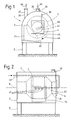
- the device 1 shown in FIGS. 1 and 2 serves to move and treat a particulate material, for example for agglomeration and pelletizing and / or Coating good particles to form a drug.
- the device 1 has a frame 2 and one on this attached housing 3. Its wall has a vertical Front wall with an opening. This is by a Locking element 4 closed, that of a door with two Wings.
- the housing 3 has other openings, those with not drawn, adjustable and / or detachable fastened closure elements are closed.
- the housing 3 encloses an interior of the housing on all sides at least dust-tight and, for example, also gas-tight against the environment is complete.
- a drum 7 is arranged in the interior of the housing.
- the Drum 7 is essentially rotationally symmetrical to one horizontal axis 8 and still separately in Fig. 3 as well partially drawn in Fig. 4.
- the drum 7 has a Axis 8 and a drum interior in cross section enclosing wall 10.
- This has a cross section generally circular, namely essentially cylindrical wall 11 or a cylindrical shell.
- the cylindrical wall 11 has an inner and an outer surface and consists, like preferably also the remaining parts of the Wall 10, made of a metallic, weldable material, for example stainless steel.
- the cylindrical wall is out a square, i.e. rectangular or possibly formed square piece of sheet metal.
- each Perforation hole 14 has one in the inner surface according to FIG. 4 the wall 12 opening, cylindrical hole portion 15 and a conical widening outwards from this Hole section 16.
- the perforation holes 14 are in generally evenly along and around axis 8 spread around.
- the middle one, generally perforated Wall section 13 of the cylindrical wall 11 has, however, in the to the axis 8 parallel weld 12 on both sides of this one along this, strip-shaped, narrow, compact, i.e. hole-free Wall section 18.
- the cylindrical wall 11 has two circular edges and between these and the middle, perforated wall section 13 each have an annular, compact, i.e. hole-free wall section 17.
- the wall 10 also has two at the two ends of the cylindrical wall 11 adjoining, away from this tapered, conical walls 19. Each of these is on its own further end by a weld 20 firm, non-detachable and tightly connected to the cylindrical wall 11.
- the narrower end the conical on the left in Figures 1 and 2 Wall 19 is welded to a cylindrical neck 21.
- the conical walls 19 and the necks 21, 22 are compact - i.e. hole-free - and gas-tight.
- the neck 21 is on its end facing away from the walls 11, 19 with an im general, flat, radial, radial over it protruding disk 23 connected, namely welded.
- the Disk 23 closes the interior of the drum at the end of Neck 21 close to the environment.
- the neck 21 still with one enclosing it over its entire length Sleeve reinforced at its ends with the neck 21 and / or with the disk 23 and the closer to this located, conical wall 19 is welded.
- the other, short neck 22 is open at its free end.
- Wire mesh 27 has, for example, stainless steel existing, crossing wires. These are with the Crossing points firmly and immovably connected to each other, namely sintered.
- the wire mesh 27 has two to each other parallel edges 28 and two mutually parallel edges 29.
- the wires of the wire mesh are at these edges 28, 29 welded together and fused together.
- the Wire mesh lies in a rotationally symmetrical axis 8 Surface, has the shape of a not completely self-contained, the axis 8 approximately enclosing cylinder has one Inner surface and an outer surface and lies with the the latter directly on the inner surface of the cylindrical Wall 11 on.
- Each of the two edges 28 of the wire mesh 27 forms almost a circle and is located at the Inner surface of one of the hole-free, ring-shaped Wall sections 17.
- Each of the two edges 29 of the wire mesh is straight and is on the inside of one of the hole-free, strip-shaped wall sections 18. Die Edge areas of the wire mesh therefore protrude slightly on all sides beyond the perforation of the wall 11 so that the Wire mesh covered all perforation holes 14.
- the Wire mesh 27 lies essentially with its whole Outside surface - namely with the exception of the Perforation holes 14 outer surface sections immediately on the inner surface of the cylindrical wall 11.
- the wire mesh is also essentially all of it Outer surface directly and insolubly on the wall 11 attached, namely at the contact points of the wires of the Wire mesh and the wall 11 sintered to it.
- the For example, wires of the wire mesh were originally in Cross-section circular everywhere. At the finished and on the wall 11 attached wire mesh, the wires are for example in Cross-section still roughly circular in places, however flattened at least at the sintered points.
- the Wire mesh has openings or pores whose light Mesh size or pore size is significantly smaller than that clear width of the perforation holes 14, i.e. as the Diameter of the cylindrical hole sections 15.
- FIGS. 3 and 4 are sometimes not to scale. 3 are in particular the perforation holes compared to the drum dimensions with exaggerated sizes and distances from each other drawn. Furthermore, the wires of the wire mesh 27 in Fig. 4 compared to the thickness of the wall 11 with exaggerated thicknesses drawn. In addition, the wire mesh is simplified, schematically and represented with round wires.
- the maximum diameter the drum 7, i.e. the outer diameter of the cylindrical Wall 11 or the cylindrical shell is, for example 400 mm to 2,000 mm.
- the thickness measured radially to axis 8 the cylindrical wall 11 is preferably in the range of 2 mm to 5 mm and is, for example, about 3 mm to 4 mm.
- the clear width of the perforation holes 14, i.e. the diameter the cylindrical hole section is preferably in the range from 2 mm to 4 mm and is, for example, approximately 2.5 mm to 3 mm.
- the clear mesh size or pore size of the wire mesh can depend on the particle sizes of the processed Goods are specified, is typically at most 1 mm and for example about 0.1 mm to 0.5 mm.
- the diameter and / or other characteristic thicknesses of the wires are preferably about 0.05 mm to 0.3 mm.
- the drum 7 is at the neck 21 enclosing Sleeve with bearing means, not shown, about axis 8 rotatably mounted and with a likewise not shown Drive device connected.
- a drawn in FIG. hollow cylindrical, open at both ends sleeve 31 is in Housing 3 fixed coaxially to axis 8.
- One open end the sleeve 31 is sealed by the closure element 4 completed when this is in the in Figures 1 and 2 drawn closed position.
- the other open The end of the sleeve 31 is in and / or in the hollow neck 22 of the drum 7, so that the drum interior with the Interior of the sleeve 31 is connected, the connection possibly sealed with a gasket.
- the frame 2 is indicated in FIG. 1 Guide means 32 provided.
- gas guide means 33 present to gas - for example air - through the drum interior and at least a portion of the gas permeable To direct wall section 13 of the drum 7.
- the gas guide 33 have a gas transmission shoe 34 which for example roughly the same as the one already quoted EP 0 137 151 A disclosed gas transmission shoe.
- the gas transfer shoe 34 is of the guide means 32 slidably guided that it is horizontal or easy inclined direction against the axis 8 and moved away from this and from a closable opening in the housing 3 this can be removed. Also fixatives present to the gas transfer shoe 34 in different Positions and in particular in that in FIGS. 1 and 2 to fix the drawn operating position.
- the gas transfer shoe 34 is in the operating position in one of the lower quadrants of the drum at least to some extent close to the cylindrical wall 11 of the drum 7 and covers an area of wall 11. That of the gas transfer shoe 34 covered area of the wall 11 extends over the entire axial extent of the gas permeable Wall section 13 and a circumferential sector of this.
- the Gas transfer shoe 34 consists of a hollow box and delimits a chamber. The gas transfer shoe has on his an opening on the wall 11 of the drum, so that the chamber is open towards the drum.
- the gas guide 33 also have two gas lines 36 and 37.
- the Gas line 36 opens into the interior of the sleeve 31 or in the between the wall of the housing 3 and the drum 7 existing, free area of the housing interior and is So either through the sleeve 31 or through the gas transmission shoe covered area of the gas permeable Wall section 13 through with the drum interior connected.
- the gas line 37 is connected to the chamber of the gas transfer shoe 34 connected.
- the gas guide means 33 have also various, not shown, with the lines 36 and 37 connected elements, namely filters, at least one Pump with a blower and for example at least one more Dosing device with a flap and a heating device for Heating the supplied air or other supplied Gases on.
- a spray device 39 with a through the closure member 4 into the drum interior protruding spray member 40 connected, some along the Axis 8 has distributed spray nozzles.
- the cylindrical wall 11 serving as a flat quadrangular, i.e. Rectangular or possibly square-shaped piece of sheet metal provided, for example with the necessary Cut off dimensions from a larger sheet of metal.
- a wire mesh 27 is also provided, for example unrolled from a wound wire mesh supply and opened cut the desired size. The wires of the Wire mesh is cut before or possibly after cutting of the wire mesh pressed against each other and with each other sintered. After sintering the wires and after Cutting the wire mesh 27, the wires in the Edges 28, 29 of the wire mesh 27 welded together.
- the above wire ends melted and welded to other wires to prevent afterwards when operating the facility at the Edges of the wire mesh break off pieces of wire and into a with the goods treated at the facility.
- the wire mesh edges becomes flat Wire mesh in a sintering furnace to form the wall 11 serving, still flat piece of sheet metal pressed and essentially for the entire surface facing the sheet metal piece Wire mesh is firmly connected to the piece of sheet metal by sintering.
- the piece of sheet metal and the attached to it Wire mesh bent together into a cylinder and the abutting edges of the sheet metal piece with each other welded so that the weld seam 12 is formed and that Sheet metal piece forms the cylindrical wall 11.
- the two conical walls 19 are also made by bending originally flat sheet metal pieces and by welding abutting edges of the sheet metal pieces formed and then welded to the cylindrical wall 11, the Weld seams 20 arise.
- the two necks 21, 22 is at least the longer neck 21 also from one originally formed flat piece of sheet metal and with the rest Wall 10 welded.
- the closure element 4 temporarily opened and a batch of the particulate to be treated in introduced the drum interior.
- the drum 7 in the direction of rotation indicated by arrow 43 in FIG. 1 turned.
- the particles abutting the wall 11 of the drum of the goods are lifted up by the rotating drum lifted and then slide or roll further inside down so that a particle bed 44 with moving particles arises.
- the particle bed 44 covers an area of the gas-permeable wall section 13, this area over the entire opening of the gas transmission shoe 34 extends.
- Air is also passed through with the gas guide means 33 the gas line 36 is supplied and through the gas line 37 aspirated, as is shown in FIG. 1 by arrows 45 and 46 is indicated.
- the Spray material can for example be a binder for Agglomerate and pelletize the particles or Contain coating material for coating the particles. in the the rest of the time there is the possibility of the particles first to agglomerate larger particles - for example pellets and then cover it with a coating.
- the particles can continue for a certain period of time without Spraying in the drum moves and with that through the Particle bed air to be dried.
- the supplied air can be heated at least temporarily become. If the particles are dry, for example open the closure element 4 and the particles through the Closure element 4 existing opening of the housing 3 through take out of the drum.
- the drum 7 partially shown in FIG. 5 has one cylindrical wall 11, the central wall portion 13 is the same or is perforated similarly to that previously described Drum. 5, however, instead of single-layer wire mesh 27 on a multi-layer rotary fabric 51.
- This has at least two wire mesh layers, namely for example a first wire mesh layer 52, a second one Wire mesh layer 53 and a third wire mesh layer 54.
- Each Wire mesh layer 52, 53, 54 consists of one another sintered wires.
- the three wire mesh layers are also at the contact points of their wires also with each other sintered.
- the first wire mesh layer 52 lies on the Inner surface of the wall 12 and consists of relatively coarse Wires.
- the second, middle wire mesh layer 53 has finer Wires and narrower pores or smaller mesh sizes than the first wire mesh layer.
- the third wire mesh layer 54 borders on the free drum interior and has thicker ones Wires as well as further pores or larger clear mesh sizes than the second wire mesh layer 53.
- the innermost wire mesh layer 52 and the outermost wire mesh layer 54 can be the same or different wire thicknesses and the same or different have clear mesh sizes.
- the second, middle wire mesh layer 53 therefore sets the minimum size of that of the multilayer Wire mesh 51 retained particles.
- the first Wire mesh layer 52 serves as a support wire mesh layer to the second, finer wire mesh layer 53 at the openings of the Support perforation holes 14.
- the third, the free one Wire mesh layer 54 adjacent to the drum interior serves as Protective wire mesh layer to protect the finer wire mesh layer 53.
- the clear mesh size can be at least at second, the smallest mesh size wire mesh layer 53 the same as for the single-layer wire mesh 27 at most 1 mm and for example about 0.1 mm to 0.5 mm or even be less than 0.1 mm.
- the wire mesh 51 has four Edges, one of which can be seen in FIG. 5 and with 55 is designated. The wires of the three wire mesh layers are included welded together on the four edges of the wire mesh. Unless otherwise stated, the 5 partially identical or similar drum shown in FIG be designed like that with reference to FIGS. 1 to 4 described drum.
- the setup can be changed in other ways become.
- the wire mesh could, for example, be two wire mesh layers have, the one of which is the minimum size of the retained particles and the other thicker Has wires as well as larger clear mesh sizes and either abuts the inner surface of the perforated wall or against the adjoining the free interior of the drum.
- the wire mesh may possibly be disrupted during manufacture the cylindrical wall 11 up to directly to each other abutting, in the finished drum through the weld 12 interconnected edges of the wall 11 forming Extend piece of sheet metal.
- the wire mesh then extends in the finished drum along the entire circumference of the perforated wall.
- the cylindrical wall can also have a removal opening have, which with an adjustable closure member, for example one can be pivoted on the rest of the wall held flap, either closed or removable of the material contained in the drum can be released.
- the closure member can, for example, with one on the Adjusted drum-mounted pneumatic actuator which is similar to the one already developed cited EP 0 137 151 A and the corresponding US 4,543,906 A. That used to form the cylindrical wall serving sheet metal piece can then be used to form the Hole serving opening or at least one of its two later welded edges one Have incision.
- the cylindrical wall can, however, take place which are also formed from two pieces of sheet metal, of which the one, bigger over most of the scope stretches and the other, smaller, strip-shaped the Removal opening limited, at least then the larger one Sheet metal piece is perforated. In this case they are axial edges of the larger, perforated piece of sheet metal at least partly no longer directly, but only indirectly connected to each other via the smaller piece of sheet metal. Possibly two or more wire mesh can then be used be present on different, perforated Wall sections are attached and together all Perforation holes against the free interior of the drum cover.
- the closure element for closing the removal opening can be compact and hole-free, for example.
- the Wire mesh is then dimensioned so that it is in the wall Area of the closable opening not covered. It is however also possible, the closure member also as gas permeable, perforated wall section with Form perforation holes and the latter on the Inside of the closure member with one on it attached, separate wire mesh to cover.
- the drum can also be in its interior arranged blades attached to the conical walls 19 or other conveyor elements to be provided for particles of a good in the drum when turning the Also move the drum in the axial direction and the To improve the mixing of the product.
- gas-permeable wall section and the wire mesh arranged on it instead of cylindrical possibly at least partially conical his.
Landscapes
- Life Sciences & Earth Sciences (AREA)
- Chemical & Material Sciences (AREA)
- Engineering & Computer Science (AREA)
- Food Science & Technology (AREA)
- Polymers & Plastics (AREA)
- Combined Means For Separation Of Solids (AREA)
- Glanulating (AREA)
- Medical Preparation Storing Or Oral Administration Devices (AREA)
- Powder Metallurgy (AREA)
- Crushing And Grinding (AREA)
Claims (10)
- Tambour comprenant un espace intérieur destiné à recevoir et à déplacer une matière en fines particules, un axe (8), une paroi métallique (11) entourant ce dernier et présentant des perforations (14) et une surface intérieure, les perforations (14) étant séparées de l'espace intérieur par au moins un tissu et le ou chaque tissu comportant une surface extérieure et une largeur de mailles qui soit inférieure à une largeur des perforations (14), caractérisé en ce que le ou chaque tissu est une toile métallique (27, 51) dont essentiellement l'ensemble de sa surface extérieure est appliquée contre la surface intérieure de la paroi (11) et qui est fixée à la paroi (11) par frittage essentiellement avec la totalité de sa surface extérieure.
- Tambour selon la revendication 1, caractérisé en ce que la ou chaque toile métallique (27, 51) présente des fils métalliques frittés entre eux.
- Tambour selon la revendication 1 ou 2, caractérisé en ce que la ou chaque toile métallique (27, 51) présente des bords (28, 29, 55) et des fils métalliques qui sont soudés entre eux au niveau des bords.
- Tambour selon l'une des revendications 1 à 3, caractérisé en ce que la ou au moins une toile métallique (27) est monocouche.
- Tambour selon la revendication 4, caractérisé en ce que la ou chaque toile métallique (27) présente une largeur de mailles de 1 mm au maximum.
- Tambour selon l'une des revendications 1 à 3, caractérisé en ce que la ou au moins une toile métallique (51) présente au moins deux couches de toile métallique superposées (52, 53, 54).
- Tambour selon la revendication 6, caractérisé en ce qu'au moins une couche de toile métallique (53) présente une largeur de mailles de 1 mm au maximum.
- Dispositif comprenant un tambour (7) selon l'une des revendications 1 à 7, caractérisé en ce que le tambour (7) est monté dans un bâti (2) de manière à pouvoir tourner autour de l'axe (8), et en ce que des moyens pour amener du gaz (33) sont prévus pour injecter du gaz à travers les perforations (14) et la toile métallique (27, 51) dans au moins une partie de la paroi (11) lorsque le tambour (7) tourne.
- Dispositif selon la revendication 8, caractérisé en ce que les moyens pour amener du gaz (33) présentent un diffuseur de gaz (34) et des moyens pour maintenir ce dernier sur le bâti (2) pendant que le tambour (7) tourne, de telle manière qu'il soit appliqué contre une partie de la surface extérieure de la paroi (11) afin de laisser le gaz passer à travers des perforations (14) de la paroi (11) et à travers la ou au moins une toile métallique (27, 51).
- Procédé pour fabriquer un tambour selon l'une des revendications 1 à 7, sachant que l'on fabrique au moins une pièce de tôle essentiellement plane présentant des perforations (14) et servant à former la paroi (11), caractérisé en ce que l'on fabrique une toile métallique (28, 51) essentiellement plane et qu'on l'applique avec une surface constituant la surface extérieure de la toile métallique (27, 51) du tambour fini contre une surface de la pièce de tôle représentant ultérieurement, sur le tambour achevé, la surface intérieure de la paroi (11), avant de la fixer par frittage, essentiellement avec l'ensemble de sa surface extérieure, sur la pièce de tôle, en ce que la pièce de tôle avec la ou chaque toile métallique (27, 51) qui y est fixée est cintrée, et en ce que les bords de la pièce de tôle sont reliés entre eux directement et/ou indirectement.
Applications Claiming Priority (3)
| Application Number | Priority Date | Filing Date | Title |
|---|---|---|---|
| CH175597 | 1997-07-17 | ||
| CH1755/97 | 1997-07-17 | ||
| CH175597 | 1997-07-17 |
Publications (2)
| Publication Number | Publication Date |
|---|---|
| EP0891808A1 EP0891808A1 (fr) | 1999-01-20 |
| EP0891808B1 true EP0891808B1 (fr) | 2002-03-27 |
Family
ID=4217812
Family Applications (1)
| Application Number | Title | Priority Date | Filing Date |
|---|---|---|---|
| EP98810614A Expired - Lifetime EP0891808B1 (fr) | 1997-07-17 | 1998-07-02 | Tambour pour recevoir un produit en particule, dispositif contenant un tambour et procédé pour la fabrication du tambour |
Country Status (6)
| Country | Link |
|---|---|
| US (1) | US6105533A (fr) |
| EP (1) | EP0891808B1 (fr) |
| JP (1) | JPH1191870A (fr) |
| DE (1) | DE59803485D1 (fr) |
| DK (1) | DK0891808T3 (fr) |
| ES (1) | ES2172108T3 (fr) |
Families Citing this family (10)
| Publication number | Priority date | Publication date | Assignee | Title |
|---|---|---|---|---|
| US8844160B2 (en) | 1997-04-29 | 2014-09-30 | Whirlpool Corporation | Modular fabric revitalizing system |
| KR100446758B1 (ko) * | 2001-08-22 | 2004-09-01 | 엘지전자 주식회사 | 의류 건조기 |
| KR101093878B1 (ko) * | 2004-06-05 | 2011-12-13 | 엘지전자 주식회사 | 건조기의 드럼 장치 |
| DE102005019443B4 (de) * | 2005-04-21 | 2007-08-16 | Glatt Maschinen- Und Apparatebau Ag | Trommel zum Beschichten von körnigen Substraten |
| US7735345B2 (en) | 2005-12-30 | 2010-06-15 | Whirlpool Corporation | Automatic fabric treatment appliance with a manual fabric treatment station |
| US7665227B2 (en) | 2005-12-30 | 2010-02-23 | Whirlpool Corporation | Fabric revitalizing method using low absorbency pads |
| US7921578B2 (en) * | 2005-12-30 | 2011-04-12 | Whirlpool Corporation | Nebulizer system for a fabric treatment appliance |
| DE102006023389A1 (de) * | 2006-05-17 | 2007-11-22 | Herbert Kannegiesser Gmbh | Verfahren und Vorrichtung zum Behandeln, vorzugsweise Waschen, Schleudern und/oder Trocknen, von Wäsche |
| ES2369166T3 (es) * | 2007-09-03 | 2011-11-28 | Arçelik Anonim Sirketi | Secadora. |
| CN103040621A (zh) * | 2011-10-15 | 2013-04-17 | 四川制药制剂有限公司 | 一种封闭式易清洗包衣机 |
Family Cites Families (7)
| Publication number | Priority date | Publication date | Assignee | Title |
|---|---|---|---|---|
| GB1284722A (en) * | 1968-08-10 | 1972-08-09 | Simon Ratowsky | Processing of photographic material |
| FR2065417A5 (en) * | 1969-10-14 | 1971-07-23 | Unilever Nv | Granulating device |
| US3952757A (en) * | 1974-03-19 | 1976-04-27 | Huey John A | Rotary processing apparatus |
| ZA774339B (en) * | 1976-07-28 | 1979-02-28 | Dravo Corp | Two concentric tandem rotating drums |
| EP0137150B1 (fr) * | 1981-05-22 | 1987-08-26 | Glatt Maschinen- und Apparatebau AG | Dispositif pour recouvrir des particules, notamment des médicaments sous forme de particules telles que des comprimés |
| JPS5991865A (ja) * | 1982-11-18 | 1984-05-26 | Kumeta Seisakusho:Kk | 粒状ワカメの製造法 |
| SU1257065A1 (ru) * | 1984-11-05 | 1986-09-15 | Уральский научно-исследовательский и проектный институт строительных материалов | Устройство дл производства гранулированного шлака |
-
1998
- 1998-07-02 DE DE59803485T patent/DE59803485D1/de not_active Expired - Lifetime
- 1998-07-02 DK DK98810614T patent/DK0891808T3/da active
- 1998-07-02 ES ES98810614T patent/ES2172108T3/es not_active Expired - Lifetime
- 1998-07-02 EP EP98810614A patent/EP0891808B1/fr not_active Expired - Lifetime
- 1998-07-14 US US09/114,919 patent/US6105533A/en not_active Expired - Lifetime
- 1998-07-15 JP JP10200530A patent/JPH1191870A/ja active Pending
Also Published As
| Publication number | Publication date |
|---|---|
| DK0891808T3 (da) | 2002-07-22 |
| JPH1191870A (ja) | 1999-04-06 |
| EP0891808A1 (fr) | 1999-01-20 |
| ES2172108T3 (es) | 2002-09-16 |
| DE59803485D1 (de) | 2002-05-02 |
| US6105533A (en) | 2000-08-22 |
Similar Documents
| Publication | Publication Date | Title |
|---|---|---|
| DE2741710C2 (de) | Vorrichtung zum Trennen von Feststoffen und Flüssigkeiten aus einer Suspension | |
| DE3687143T2 (de) | Vorrichtung und verfahren fuer die erzeugung eines faservlieses. | |
| EP0781585B1 (fr) | Dispositif de dépoussièrage d'un gaz | |
| EP0891808B1 (fr) | Tambour pour recevoir un produit en particule, dispositif contenant un tambour et procédé pour la fabrication du tambour | |
| DE2405854C3 (de) | Filterpresse | |
| EP0103900A1 (fr) | Dispositif à lit fluidifié | |
| DE19819980B4 (de) | Filtereinrichtung für eine Prozeßapparatur | |
| DD200216A5 (de) | Schlauchfilter fuer die reinigung von gasen | |
| DE69525055T2 (de) | Siebsystem für eine ionenaustauscherkolonne | |
| DE2436543A1 (de) | Anlage zur verarbeitung von muell | |
| CH646614A5 (de) | Wirbelschichtapparatur. | |
| DE524795C (de) | Vorrichtung zum Verteilen von Tabak | |
| AT384562B (de) | Siebtrommel | |
| DE19543976C2 (de) | Siebtrommel zum Konditionieren und Klassieren von körnigem Gut | |
| DE4100575C2 (fr) | ||
| DE8800891U1 (de) | Vorrichtung zum künstlichen Altern und Aufhellen von Jeansstoffen | |
| DE69512536T2 (de) | Trenneinrichtung | |
| AT392300B (de) | Eindicker | |
| DE3939645C3 (de) | Staubabscheider mit schlauchförmigen Filterelementen und Verfahren zum Wechseln derselben | |
| DE60306063T2 (de) | Siebvorrichtung | |
| DE9206445U1 (de) | Kompostierer | |
| DE29912585U1 (de) | Sichtanlage für fasrige Produkte, insbesondere für expandierten Schnittabak | |
| DE3742911C2 (de) | Verfahren und Vorrichtung zur Expandierung von Tabakmaterial | |
| DE3246198C2 (de) | Verfahren und Trommel zum Trocknen von feuchten Schüttgütern | |
| EP0096192B1 (fr) | Procédé et installation de traitement à l'eau de matières textiles sans fin |
Legal Events
| Date | Code | Title | Description |
|---|---|---|---|
| PUAI | Public reference made under article 153(3) epc to a published international application that has entered the european phase |
Free format text: ORIGINAL CODE: 0009012 |
|
| AK | Designated contracting states |
Kind code of ref document: A1 Designated state(s): BE CH DE DK ES FR GB IE IT LI NL SE |
|
| AX | Request for extension of the european patent |
Free format text: AL;LT;LV;MK;RO;SI |
|
| 17P | Request for examination filed |
Effective date: 19990205 |
|
| AKX | Designation fees paid |
Free format text: BE CH DE DK ES FR GB IE IT LI NL SE |
|
| 17Q | First examination report despatched |
Effective date: 20000516 |
|
| GRAG | Despatch of communication of intention to grant |
Free format text: ORIGINAL CODE: EPIDOS AGRA |
|
| GRAG | Despatch of communication of intention to grant |
Free format text: ORIGINAL CODE: EPIDOS AGRA |
|
| GRAH | Despatch of communication of intention to grant a patent |
Free format text: ORIGINAL CODE: EPIDOS IGRA |
|
| REG | Reference to a national code |
Ref country code: GB Ref legal event code: IF02 |
|
| GRAH | Despatch of communication of intention to grant a patent |
Free format text: ORIGINAL CODE: EPIDOS IGRA |
|
| GRAA | (expected) grant |
Free format text: ORIGINAL CODE: 0009210 |
|
| AK | Designated contracting states |
Kind code of ref document: B1 Designated state(s): BE CH DE DK ES FR GB IE IT LI NL SE |
|
| REG | Reference to a national code |
Ref country code: CH Ref legal event code: NV Representative=s name: PATENTANWALTSBUERO EDER AG Ref country code: CH Ref legal event code: EP |
|
| GBT | Gb: translation of ep patent filed (gb section 77(6)(a)/1977) |
Effective date: 20020403 |
|
| REF | Corresponds to: |
Ref document number: 59803485 Country of ref document: DE Date of ref document: 20020502 |
|
| REG | Reference to a national code |
Ref country code: IE Ref legal event code: FG4D Free format text: GERMAN |
|
| ET | Fr: translation filed | ||
| REG | Reference to a national code |
Ref country code: DK Ref legal event code: T3 |
|
| REG | Reference to a national code |
Ref country code: ES Ref legal event code: FG2A Ref document number: 2172108 Country of ref document: ES Kind code of ref document: T3 |
|
| PLBE | No opposition filed within time limit |
Free format text: ORIGINAL CODE: 0009261 |
|
| STAA | Information on the status of an ep patent application or granted ep patent |
Free format text: STATUS: NO OPPOSITION FILED WITHIN TIME LIMIT |
|
| 26N | No opposition filed |
Effective date: 20021230 |
|
| REG | Reference to a national code |
Ref country code: FR Ref legal event code: PLFP Year of fee payment: 19 |
|
| PGFP | Annual fee paid to national office [announced via postgrant information from national office to epo] |
Ref country code: ES Payment date: 20160628 Year of fee payment: 19 |
|
| PGFP | Annual fee paid to national office [announced via postgrant information from national office to epo] |
Ref country code: NL Payment date: 20160711 Year of fee payment: 19 |
|
| PGFP | Annual fee paid to national office [announced via postgrant information from national office to epo] |
Ref country code: DK Payment date: 20160712 Year of fee payment: 19 Ref country code: IE Payment date: 20160711 Year of fee payment: 19 |
|
| PGFP | Annual fee paid to national office [announced via postgrant information from national office to epo] |
Ref country code: SE Payment date: 20160712 Year of fee payment: 19 Ref country code: FR Payment date: 20160712 Year of fee payment: 19 |
|
| PGFP | Annual fee paid to national office [announced via postgrant information from national office to epo] |
Ref country code: BE Payment date: 20160624 Year of fee payment: 19 |
|
| PGFP | Annual fee paid to national office [announced via postgrant information from national office to epo] |
Ref country code: GB Payment date: 20170628 Year of fee payment: 20 |
|
| PGFP | Annual fee paid to national office [announced via postgrant information from national office to epo] |
Ref country code: CH Payment date: 20170726 Year of fee payment: 20 Ref country code: IT Payment date: 20170720 Year of fee payment: 20 Ref country code: DE Payment date: 20170627 Year of fee payment: 20 |
|
| REG | Reference to a national code |
Ref country code: DK Ref legal event code: EBP Effective date: 20170731 |
|
| REG | Reference to a national code |
Ref country code: NL Ref legal event code: MM Effective date: 20170801 |
|
| REG | Reference to a national code |
Ref country code: SE Ref legal event code: EUG |
|
| REG | Reference to a national code |
Ref country code: IE Ref legal event code: MM4A |
|
| REG | Reference to a national code |
Ref country code: FR Ref legal event code: ST Effective date: 20180330 |
|
| PG25 | Lapsed in a contracting state [announced via postgrant information from national office to epo] |
Ref country code: SE Free format text: LAPSE BECAUSE OF NON-PAYMENT OF DUE FEES Effective date: 20170703 Ref country code: NL Free format text: LAPSE BECAUSE OF NON-PAYMENT OF DUE FEES Effective date: 20170801 Ref country code: IE Free format text: LAPSE BECAUSE OF NON-PAYMENT OF DUE FEES Effective date: 20170702 |
|
| REG | Reference to a national code |
Ref country code: CH Ref legal event code: PCAR Free format text: NEW ADDRESS: HOLEESTRASSE 87, 4054 BASEL (CH) |
|
| PG25 | Lapsed in a contracting state [announced via postgrant information from national office to epo] |
Ref country code: FR Free format text: LAPSE BECAUSE OF NON-PAYMENT OF DUE FEES Effective date: 20170731 |
|
| REG | Reference to a national code |
Ref country code: BE Ref legal event code: MM Effective date: 20170731 |
|
| REG | Reference to a national code |
Ref country code: DE Ref legal event code: R071 Ref document number: 59803485 Country of ref document: DE |
|
| REG | Reference to a national code |
Ref country code: GB Ref legal event code: PE20 Expiry date: 20180701 |
|
| PG25 | Lapsed in a contracting state [announced via postgrant information from national office to epo] |
Ref country code: DK Free format text: LAPSE BECAUSE OF NON-PAYMENT OF DUE FEES Effective date: 20170731 |
|
| REG | Reference to a national code |
Ref country code: CH Ref legal event code: PL |
|
| PG25 | Lapsed in a contracting state [announced via postgrant information from national office to epo] |
Ref country code: BE Free format text: LAPSE BECAUSE OF NON-PAYMENT OF DUE FEES Effective date: 20170731 |
|
| REG | Reference to a national code |
Ref country code: ES Ref legal event code: FD2A Effective date: 20181102 |
|
| PG25 | Lapsed in a contracting state [announced via postgrant information from national office to epo] |
Ref country code: GB Free format text: LAPSE BECAUSE OF EXPIRATION OF PROTECTION Effective date: 20180701 |
|
| PG25 | Lapsed in a contracting state [announced via postgrant information from national office to epo] |
Ref country code: ES Free format text: LAPSE BECAUSE OF NON-PAYMENT OF DUE FEES Effective date: 20170703 |