EP0891897A1 - Flexible Schutzhülle zur SIcherung der Durchfuhr eines elektrischen Kabelbundes zwischen zwei Teilen einer Installation wie einem Kraftfahrzeug - Google Patents
Flexible Schutzhülle zur SIcherung der Durchfuhr eines elektrischen Kabelbundes zwischen zwei Teilen einer Installation wie einem Kraftfahrzeug Download PDFInfo
- Publication number
- EP0891897A1 EP0891897A1 EP98401710A EP98401710A EP0891897A1 EP 0891897 A1 EP0891897 A1 EP 0891897A1 EP 98401710 A EP98401710 A EP 98401710A EP 98401710 A EP98401710 A EP 98401710A EP 0891897 A1 EP0891897 A1 EP 0891897A1
- Authority
- EP
- European Patent Office
- Prior art keywords
- opening
- end piece
- engagement
- protective sheath
- sheath
- Prior art date
- Legal status (The legal status is an assumption and is not a legal conclusion. Google has not performed a legal analysis and makes no representation as to the accuracy of the status listed.)
- Granted
Links
Images


Classifications
-
- B—PERFORMING OPERATIONS; TRANSPORTING
- B60—VEHICLES IN GENERAL
- B60R—VEHICLES, VEHICLE FITTINGS, OR VEHICLE PARTS, NOT OTHERWISE PROVIDED FOR
- B60R16/00—Electric or fluid circuits specially adapted for vehicles and not otherwise provided for; Arrangement of elements of electric or fluid circuits specially adapted for vehicles and not otherwise provided for
- B60R16/02—Electric or fluid circuits specially adapted for vehicles and not otherwise provided for; Arrangement of elements of electric or fluid circuits specially adapted for vehicles and not otherwise provided for electric constitutive elements
- B60R16/0207—Wire harnesses
- B60R16/0215—Protecting, fastening and routing means therefor
- B60R16/0222—Grommets
Definitions
- the invention relates to a flexible protective sheath made of a material elastomer to ensure the passage between two parts of an installation such as a motor vehicle, at least one electric harness.
- the electrical harnesses In certain parts of their journey inside the vehicle, the electrical harnesses must be protected by an elastomer sheath, waterproof and resistant to wear and / or soiling.
- the sheath is fixed to one of its ends, on a first part of the vehicle body and, at its second end, on a second part of the body.
- the parts of the vehicle body between which the sheaths for the passage of electrical harnesses may be fixed parts such as the vehicle body or moving parts such as the doors, the rear flap or the trunk of the vehicle.
- the inner diameter of the protective elastomer sheaths of motor vehicle is designed to allow passage with little play one or more electrical harnesses or conduits.
- Electric harnesses of motor vehicles generally have at their ends connection parts made of plastic or metallic material, the dimensions of which can be much larger than the diameter of the conductors of the beam.
- Protective elastomer sheaths have at their ends end caps allowing their fixing by clipping in openings formed in parts of the vehicle body.
- the connector must be inserted into the nozzle, when the beam is put in place in the sheath. Due to the high value of the coefficient of friction between the rubber of the sheath and of the end-piece and the plastic material constituting usually the body of wiring harness connectors, and deformability reduction of the tip, the placement of connectors in the tips protective sheaths is a difficult operation.
- the end of the sheath in which the connector is inserted lack of rigidity, so that it is liable to deform, at the moment where the attachment is carried out on the vehicle body automotive, thereby engaging and fixing the nozzle in the opening bodywork is a difficult operation.
- such an embodiment of the tip of a sheath of material elastomer does not facilitate the introduction and fixing of a connector harness inside the end cap.
- the connector introduced inside the end of the sheath which is male or female, must be connected to a connector of the opposite type accessible inside the opening of the bodywork in which we put and fix the nozzle sheath.
- the connector disposed in the end piece is held by simple contact against the inner surface of the nozzle, immobilization of the connector in the end cap is not effectively secured, which can complicate the operations to be carried out when connecting the male and female connectors.
- the connector which is not maintained from firm way inside the mouthpiece can be moved. In some In this case, the retention of the beam (s) inside the sheath may be defective.
- the object of the invention is therefore to propose a protective sheath flexible in an elastomeric material to ensure the passage between two parts of an installation such as a motor vehicle, of at least one beam electric comprising a connecting element to at least one from its ends, the sheath having at least one end-piece for fixing it in an opening of part of the installation, at at least one of its ends, in which the connection element of the electrical harness is engaged, this protective sheath being produced in such a way that the fixing of the nozzle in the opening is facilitated and that the maintenance of the element connection of the harness in the end cap is ensured efficient manner.
- the protective sheath according to the invention comprises at less an element of engagement favoring the sliding and ensuring the fixing of the nozzle in the opening fixed to the outer periphery of the nozzle and comprising, in a radially inwardly projecting arrangement, at least a removable fixing means for the harness connection element electric.
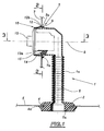
- FIG. 1 is a view in axial section along 1-1 of FIG. 2, of a sheath according to the invention and according to a first embodiment.
- Figure 2 is a partial sectional view in elevation along 2-2 of Figure 1 of the sheath.
- Figure 3 is a sectional view along 3-3 of Figure 1.
- Figure 4 is a perspective view of the engagement element of the sheath shown in Figures 1 to 3.
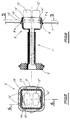
- Figure 5 is a sectional view along 5-5 of Figure 6 of a sheath according to the invention and according to a second embodiment.
- Figure 6 is a sectional view along 6-6 of Figure 5.
- FIGS 1, 2 and 3 there is shown a sheath designated so general by reference 1 intended to ensure the protection of a beam electric vehicle and the sealed passage of the beam between a door and the vehicle body.
- the sheath 1 comprises a tubular central body 1a produced in the form wavy or ringed, so that the body inside which passes the electric harness (not shown) can be deformed, by bending, by extension or compression between two parts of a motor vehicle such as a vehicle door and part of the vehicle body located the interior of the passenger compartment.
- the sheath 1 comprises, at the ends of the corrugated central body 1a, a first end piece 2 and a second end piece 3 intended to secure the ends of the sheath on the door and on the body of the motor vehicle, respectively.
- the first nozzle 2 intended to ensure the fixing of a first end of the sheath 1 inside an opening passing through a sheet metal of the door of the motor vehicle, is produced in the form of a disc made of elastomer material made of material with the corrugated body the of the sheath, during the production of the sheath by molding. Tip 2 in shape of disc and the body 1a of the sheath are coaxial and of revolution around a common axis 6.
- the end piece 2 has a groove 4 having the axis as an axis 6 which is delimited externally by an annular lip 4a intended to come to rest against a face of the sheet 5 of the motor vehicle door around the opening 5a of the sheet 5 in which a part is engaged of the nozzle 2 for fixing one end of the sheath 1 to the door plate 5.
- the end piece 2 is engaged inside the opening 5a and pushed into place in the direction of axis 6, so that the edge of the opening 5a whose diameter is substantially equal to the diameter internal minimum of the throat 4 comes to be housed in a part set back towards inside the groove 4.
- the lip 4a then comes to bear against the face of the sheet 5 opposite the engagement face of the end piece, around the opening 5a. This ensures sealing and secure attachment of the end piece 2 in the sheet 5 of the door of the motor vehicle.
- the tip 3 which is arranged at the end of the body opposite the tip 2, allows the fixing of the second end of the sheath 1 in an opening 7a of a sheet metal 7 of the body of the accessible motor vehicle inside the passenger compartment of the vehicle.
- the end piece 3 comprises a tubular part made of elastomeric material integrally with the body 1a and the end piece 2 of the sheath, during molding of the sheath, having an axis 8 perpendicular to the axis 6 of the body 1a and the end piece 2 of the sheath.
- the tubular part of elastomeric material of the end piece 3 is connected to the end of the corrugated body 1a of the sheath 1 by a bent part sheath 1 made in one piece with the body 1a, the nozzle 2 and the tubular part of the end piece 3, during the molding of the sheath 1.
- the tubular part made of elastomeric material of the end piece 3 comprises a groove 9 having for axis the axis 8 and delimited externally by a lip 9a annular radially projecting towards the outside of the tubular part elastomeric material of the tip 3.
- the edge of the opening 7a engages in the groove 9 and the annular lip 9a constitutes a sealing lip coming to bear against a surface of the sheet 7 around the opening 7a.
- the end piece 3 of the sheath 1 further comprises an element engagement 10 in a plastic material of generally annular shape.
- FIG 4 there is shown the engagement element 10 separated from the tubular part of elastomeric material of the end piece.
- the element of engagement 10 can be made in one piece, by molding, in one plastic material such as polyamide.
- the engagement element 10 comprises an annular body 10a, the internal surface is cylindrical and has a substantially equal diameter or slightly less than the diameter of the end section of the tubular part made of elastomer of end piece 3 and a slightly outer surface tapered flared in the direction from front to rear in the figure 4.
- the body 10a of the engagement element in plastic 10 has four notches 11 in each of which a finger 12 is placed made in one piece with the body 10a of item 10.
- Each of the fingers 12 has an external surface 12a inclined towards outward and backward relative to the frustoconical outer surface of the body 10a of element 10 as well as a rear end portion 12b comprising a notch facing outward and a heel inward, that is to say on the side of the finger 12 opposite the inclined external surface 12a.
- the element 10 comprises, projecting radially inwards relative to the internal surface of the body 10a, a means 14 for fixing a connector 13 of the electrical harness passing through the sheath 1 shown in the figures 1, 2 and 3.
- the fixing means 14, which is made in one piece with the body 10a of element 10, has a base 14a and a pallet 15 of fixing the connector 13.
- the pallet 15 has two lateral edges 15a, 15b of reduced thickness intended to come to engage in slides of the support surface 13a of connector 13, when fixing the connector to inside the end piece 3.
- the pallet 15 of the fixing element 14 has an end portion 15c located towards the front of the engagement element 10 through an opening 16.
- the connector 13 has on its bearing face 13 has a lug which engages in the opening 16, at the end of the sliding movement of the connector 13 on the pallet 15, making thus the fixing by clipping of the connector 13 on the fixing means 14.
- the engagement element 10 of the end piece is mounted on the end section of the tubular part made of material elastomer of the end piece 3.
- the element 10 is engaged, by its rear part on the end section of the end piece 3, until the edge front (in FIG. 4) of the body 10a of the engagement element 10 comes in abutment on a heel 17 (see FIGS. 2 and 3) of the tubular part made of material elastomer of the end piece 3.
- the engagement element is then blocked axially between the heels 17 and 17 '.
- the end portions 12b of the fingers 12 are then placed inside the groove 9.
- the base 14a of the means attachment is engaged in a slot in the tubular part of the end piece 3.
- the fingers 12 ensure the locking of the nozzle 3 on the sheet 7 by clamping a part of the sheet 7, at the periphery of the opening 7a, between the annular lip 9a of the nozzle 3 and the parts end 12b of the fingers 12.
- the connector 13 can be easily set up and fixed inside the nozzle 3, via the fixing means 14. The connector 13 is then held in a position perfectly defined inside the nozzle 3.
- the connector 13 fixed inside the end piece 3 can be easily connected to a connector opposite type (male or female) accessible inside the opening 7a.
- the connector 13 is perfectly maintained inside the end piece 3 because clipping on the plate 15 of the fixing means 14.
- the device according to the invention therefore makes it possible to ensure fixing perfect connector and facilitate the fitting and fixing of the connector sheath.
- the sheath 1 ' comprises at one of its ends a tip 2 ', identical to the tip 2 of the sheath 1 according to the first embodiment, and, at its second end, a 3 'end piece comprising an engagement element 10 'comprising fixing means 14' and 14 "for securing two connectors 13 'and 13".
- 1 'sheath can be used to pass two electrical harnesses each comprising a connector 13 'or 13 "engaged in the end piece 3'.
- the tubular end portion of elastomeric material made of material with the body of the sheath 1 ′ as well as the element 10 'engagement plastics have a square section with rounded corners, as shown in Figure 6.
- each side of the square section of the engagement element 10 'made of plastic are provided with two substantially similar fingers 12' on finger 12 of the engagement element of the end piece of the sheath according to the first embodiment.
- the tubular part made of elastomeric material of the tip 3 ′ has slots in which the support bases of the removable fixing means are engaged 14 'and 14 ".
- the assembly and disassembly of the 13 'and 13 "connectors can be made as described above with regard to connector 13 engaged in the end piece 3 of the sheath according to the first embodiment.
- the engagement and fixing of the end piece 3 ′ in the opening 7 ′ has a sheet 7 'can be produced as described above by pushing on the nozzle 3 ′ which is introduced into the opening 7 ′ a with square section. Because the connectors 13 'and 13 "are perfectly maintained inside the end piece 3 ', we can make their connection and subsequent attachment of the tip 3 'in the opening of the sheet 7' without risk of displacement of the connectors 13 'and 13 ". As in the case of the first embodiment, the engagement and the attachment of the nozzle 3 'in the opening of the sheet 7' is facilitated by the shape and the material of the engagement element 10 '.
- sheaths according to the invention having a terminal nozzle for receiving and ensuring the fixing of a number any of connectors.
- the end part made of elastomeric material of the end piece and the element engagement mounted on this end section may have a cross section of any shape.
- the end section of the end piece and the engagement element can be assembled in any way different from a commitment in force and resting on stops provided on the section end of the elastomeric material of the end piece.
- the engagement element can be produced in the form of an insert which is partially embedded in the elastomeric material of the nozzle at the time of the production of the protective sheath by molding.
- the engagement element which is generally made of plastic or metal can be made in one or in several parts. In the case where the engagement element is made in several parts and for example in two parts, these parts can be engaged separately around of the nozzle and assembled together by clipping or via mechanical elements.
- Each part of the engagement element may include a removable fixing means for a connector or, only one part of the engagement element may include a means of fixing a connector.
- the engagement element may have a number of flexible fingers different from four. However, the engagement element must include minus three flexible fingers.
- the sheath and the end piece comprising the engagement element can be obtained by a process of bi-injection, simultaneous or not, of two plastics of different hardness.
- the protective sheath according to the invention applies not only in the case of motor vehicles but also in the case of any type of vehicle or in the case of fixed installations requiring passage of electric cables between different points of the installation, with connection of electrical cable connection elements to others cable connection elements carried by the installation.
Landscapes
- Engineering & Computer Science (AREA)
- Mechanical Engineering (AREA)
- Insulating Bodies (AREA)
- Details Of Indoor Wiring (AREA)
Applications Claiming Priority (2)
| Application Number | Priority Date | Filing Date | Title |
|---|---|---|---|
| FR9708901 | 1997-07-11 | ||
| FR9708901A FR2766023B1 (fr) | 1997-07-11 | 1997-07-11 | Gaine de protection souple pour assurer le passage d'un faisceau electrique entre deux parties d'une installation telle qu'un vehicule automobile |
Publications (2)
| Publication Number | Publication Date |
|---|---|
| EP0891897A1 true EP0891897A1 (de) | 1999-01-20 |
| EP0891897B1 EP0891897B1 (de) | 2003-05-07 |
Family
ID=9509183
Family Applications (1)
| Application Number | Title | Priority Date | Filing Date |
|---|---|---|---|
| EP98401710A Expired - Lifetime EP0891897B1 (de) | 1997-07-11 | 1998-07-06 | Flexible Schutzhülle zur Sicherung der Durchfuhr eines elektrischen Kabelbundes zwischen zwei Teilen einer Installation wie einem Kraftfahrzeug |
Country Status (4)
| Country | Link |
|---|---|
| EP (1) | EP0891897B1 (de) |
| DE (1) | DE69814251T2 (de) |
| ES (1) | ES2197432T3 (de) |
| FR (1) | FR2766023B1 (de) |
Cited By (5)
| Publication number | Priority date | Publication date | Assignee | Title |
|---|---|---|---|---|
| WO2002101897A3 (de) * | 2001-06-08 | 2003-02-20 | Fritz Richard Gmbh & Co Kg | Abdichteinrichtung für eine leitungsverbindung |
| DE10101013B4 (de) * | 2000-09-18 | 2013-09-12 | Volkswagen Ag | Dichtungsanordnung für eine Leitungsdurchführung an einer Karosserieteilwandung |
| FR3048203A1 (fr) * | 2016-02-29 | 2017-09-01 | Peugeot Citroen Automobiles Sa | Agencement d'un ensemble de gaines de protection sur un vehicule automobile |
| FR3052124A1 (fr) * | 2016-06-01 | 2017-12-08 | Renault Sas | Passe-fil universel pour porte |
| FR3093682A1 (fr) * | 2019-03-11 | 2020-09-18 | Psa Automobiles Sa | Fourreau de passage de câbles et/ou faisceaux électriques pour véhicule automobile |
Families Citing this family (1)
| Publication number | Priority date | Publication date | Assignee | Title |
|---|---|---|---|---|
| ES2926802T3 (es) * | 2019-03-01 | 2022-10-28 | Nexans | Dispositivo de conexión, conexión de enchufe y procedimiento para la fabricación de una conexión de enchufe |
Citations (6)
| Publication number | Priority date | Publication date | Assignee | Title |
|---|---|---|---|---|
| DE8207358U1 (de) * | 1982-03-16 | 1982-09-23 | Simon, Hans, 5463 Unkel | Zugentlastung bewirkende Kabeldurchführung |
| DE3500359C1 (de) * | 1985-01-08 | 1986-02-13 | Daimler-Benz Ag, 7000 Stuttgart | Leitungsdurchführung bei Kraftfahrzeugen |
| DE4109804C1 (de) * | 1991-03-26 | 1992-09-17 | Mercedes-Benz Aktiengesellschaft, 7000 Stuttgart, De | |
| DE4306806A1 (en) * | 1992-03-05 | 1993-09-09 | Whitaker Corp | Electric connector for assembly in partition e.g. of motor vehicle - is secured by locking ring with two-stage rotation culminating in complete locking to housing of connector |
| DE4243557A1 (de) * | 1992-12-22 | 1994-06-23 | Opel Adam Ag | Kabeltülle |
| FR2730785A1 (fr) | 1995-02-17 | 1996-08-23 | Peugeot | Gaine de protection souple en caoutchouc pour assurer le passage d'un faisceau electrique ou d'un conduit |
-
1997
- 1997-07-11 FR FR9708901A patent/FR2766023B1/fr not_active Expired - Fee Related
-
1998
- 1998-07-06 EP EP98401710A patent/EP0891897B1/de not_active Expired - Lifetime
- 1998-07-06 DE DE69814251T patent/DE69814251T2/de not_active Expired - Lifetime
- 1998-07-06 ES ES98401710T patent/ES2197432T3/es not_active Expired - Lifetime
Patent Citations (6)
| Publication number | Priority date | Publication date | Assignee | Title |
|---|---|---|---|---|
| DE8207358U1 (de) * | 1982-03-16 | 1982-09-23 | Simon, Hans, 5463 Unkel | Zugentlastung bewirkende Kabeldurchführung |
| DE3500359C1 (de) * | 1985-01-08 | 1986-02-13 | Daimler-Benz Ag, 7000 Stuttgart | Leitungsdurchführung bei Kraftfahrzeugen |
| DE4109804C1 (de) * | 1991-03-26 | 1992-09-17 | Mercedes-Benz Aktiengesellschaft, 7000 Stuttgart, De | |
| DE4306806A1 (en) * | 1992-03-05 | 1993-09-09 | Whitaker Corp | Electric connector for assembly in partition e.g. of motor vehicle - is secured by locking ring with two-stage rotation culminating in complete locking to housing of connector |
| DE4243557A1 (de) * | 1992-12-22 | 1994-06-23 | Opel Adam Ag | Kabeltülle |
| FR2730785A1 (fr) | 1995-02-17 | 1996-08-23 | Peugeot | Gaine de protection souple en caoutchouc pour assurer le passage d'un faisceau electrique ou d'un conduit |
Cited By (6)
| Publication number | Priority date | Publication date | Assignee | Title |
|---|---|---|---|---|
| DE10101013B4 (de) * | 2000-09-18 | 2013-09-12 | Volkswagen Ag | Dichtungsanordnung für eine Leitungsdurchführung an einer Karosserieteilwandung |
| WO2002101897A3 (de) * | 2001-06-08 | 2003-02-20 | Fritz Richard Gmbh & Co Kg | Abdichteinrichtung für eine leitungsverbindung |
| FR3048203A1 (fr) * | 2016-02-29 | 2017-09-01 | Peugeot Citroen Automobiles Sa | Agencement d'un ensemble de gaines de protection sur un vehicule automobile |
| WO2017149224A1 (fr) * | 2016-02-29 | 2017-09-08 | Psa Automobiles S.A. | Agencement d'un ensemble de gaines de protection sur un vehicule automobile |
| FR3052124A1 (fr) * | 2016-06-01 | 2017-12-08 | Renault Sas | Passe-fil universel pour porte |
| FR3093682A1 (fr) * | 2019-03-11 | 2020-09-18 | Psa Automobiles Sa | Fourreau de passage de câbles et/ou faisceaux électriques pour véhicule automobile |
Also Published As
| Publication number | Publication date |
|---|---|
| DE69814251T2 (de) | 2004-04-08 |
| DE69814251D1 (de) | 2003-06-12 |
| ES2197432T3 (es) | 2004-01-01 |
| FR2766023A1 (fr) | 1999-01-15 |
| EP0891897B1 (de) | 2003-05-07 |
| FR2766023B1 (fr) | 1999-10-01 |
Similar Documents
| Publication | Publication Date | Title |
|---|---|---|
| WO2017168061A1 (fr) | Dispositif d'eclairage comportant un boitier dote d'un fut de reception pour un tronçon cylindrique d'un guide de lumiere | |
| FR2472131A1 (fr) | Dispositif de raccordement et de fixation de tuyaux pour traversees de parois | |
| WO2007003823A2 (fr) | Dispositif de fixation d'un profile enjoliveur sur un cordon profile | |
| EP0970853B1 (de) | Dichte Durchlassvorrichtung eines elektrischen Kabelbaumes durch die Durchführungsöffunug einer Fahrzeugspritzwand und Montageverfahren des elektrischen Kabelbaumes | |
| EP0379392A1 (de) | Kugelgelenk | |
| EP0891897B1 (de) | Flexible Schutzhülle zur Sicherung der Durchfuhr eines elektrischen Kabelbundes zwischen zwei Teilen einer Installation wie einem Kraftfahrzeug | |
| EP1216887A1 (de) | Vorrichtung zur Umhüllung und Befestigung eines elektrischen Kabelbaumes | |
| FR2809877A1 (fr) | Dispositif de traversee etanche d'un faisceau electrique par une ouverture de passage a travers un tablier d'un vehicule automobile et procede de montage du faisceau dans l'ouverture | |
| EP1138963B1 (de) | Haltevorrichtung für eine Bowdenzughülle | |
| FR2922691A1 (fr) | Agrafe pour le maintien de cables ou faisceaux, notamment sur la caisse ou la carrosserie d'un vehicule automobile. | |
| FR2730785A1 (fr) | Gaine de protection souple en caoutchouc pour assurer le passage d'un faisceau electrique ou d'un conduit | |
| EP0673806B1 (de) | Vorrichtung zum Befestigen von Stossstangen an der Karosserie eines Kraftfahrzeuges | |
| FR2734218A1 (fr) | Dispositif de fixation d'un faisceau electrique sur une partie d'un vehicule automobile | |
| FR2857791A1 (fr) | Accessoire pour goulotte a verrouillage automatique | |
| FR2744781A1 (fr) | Dispositif d'obturation d'une ouverture et en particulier d'une ouverture traversant une paroi d'un vehicule automobile | |
| EP1320163B1 (de) | Immobilisierungszubehör für ein elektrisches Installationsgerät mit Direktschnappverbindung in einem Kabelrinnesockel | |
| FR3013524A1 (fr) | Fourreau a embout rotatif pour faisceau electrique apte a etre monte entre le chassis et un ouvrant d'un vehicule automobile | |
| EP3966074B1 (de) | Vorrichtung zum befestigen einer zierkappe an einem hinteren lichtgehäuse für kraftfahrzeuge und verfahren zur montage mittels dieser vorrichtung | |
| FR2527015A1 (fr) | Connecteur verrouillable et deverrouillable pour cables electriques | |
| EP0730997B1 (de) | Dekoratives Teil aus Kunststoff | |
| FR2784955A1 (fr) | Dispositif de fixation d'un element exterieur de carrosserie sur une structure de vehicule, et vehicule comportant un tel dispositif | |
| EP2168811B1 (de) | Lighting or signalling device for an automobile comprising a fixing element equipped with an elastically deformable element | |
| FR2976645A1 (fr) | Douille d'etancheite destinee a un passe-cable | |
| FR2882198A1 (fr) | Dispositif de connexion pour le passage et la protection de cables electriques, ou analogues | |
| FR2826091A1 (fr) | Piece d'etancheite pour la traversee d'un faisceau electrique a travers l'ouverture d'une paroi |
Legal Events
| Date | Code | Title | Description |
|---|---|---|---|
| PUAI | Public reference made under article 153(3) epc to a published international application that has entered the european phase |
Free format text: ORIGINAL CODE: 0009012 |
|
| AK | Designated contracting states |
Kind code of ref document: A1 Designated state(s): CH DE ES GB IT LI PT SE |
|
| AX | Request for extension of the european patent |
Free format text: AL;LT;LV;MK;RO;SI |
|
| 17P | Request for examination filed |
Effective date: 19981201 |
|
| AKX | Designation fees paid |
Free format text: CH DE ES GB IT LI PT SE |
|
| GRAH | Despatch of communication of intention to grant a patent |
Free format text: ORIGINAL CODE: EPIDOS IGRA |
|
| GRAH | Despatch of communication of intention to grant a patent |
Free format text: ORIGINAL CODE: EPIDOS IGRA |
|
| GRAA | (expected) grant |
Free format text: ORIGINAL CODE: 0009210 |
|
| AK | Designated contracting states |
Designated state(s): CH DE ES GB IT LI PT SE |
|
| REG | Reference to a national code |
Ref country code: GB Ref legal event code: FG4D Free format text: NOT ENGLISH |
|
| REG | Reference to a national code |
Ref country code: CH Ref legal event code: EP |
|
| REF | Corresponds to: |
Ref document number: 69814251 Country of ref document: DE Date of ref document: 20030612 Kind code of ref document: P |
|
| PG25 | Lapsed in a contracting state [announced via postgrant information from national office to epo] |
Ref country code: LI Free format text: LAPSE BECAUSE OF NON-PAYMENT OF DUE FEES Effective date: 20030731 Ref country code: CH Free format text: LAPSE BECAUSE OF NON-PAYMENT OF DUE FEES Effective date: 20030731 |
|
| PG25 | Lapsed in a contracting state [announced via postgrant information from national office to epo] |
Ref country code: SE Free format text: LAPSE BECAUSE OF FAILURE TO SUBMIT A TRANSLATION OF THE DESCRIPTION OR TO PAY THE FEE WITHIN THE PRESCRIBED TIME-LIMIT Effective date: 20030807 Ref country code: PT Free format text: LAPSE BECAUSE OF FAILURE TO SUBMIT A TRANSLATION OF THE DESCRIPTION OR TO PAY THE FEE WITHIN THE PRESCRIBED TIME-LIMIT Effective date: 20030807 |
|
| GBT | Gb: translation of ep patent filed (gb section 77(6)(a)/1977) | ||
| REG | Reference to a national code |
Ref country code: ES Ref legal event code: FG2A Ref document number: 2197432 Country of ref document: ES Kind code of ref document: T3 |
|
| PLBE | No opposition filed within time limit |
Free format text: ORIGINAL CODE: 0009261 |
|
| REG | Reference to a national code |
Ref country code: CH Ref legal event code: PL |
|
| 26N | No opposition filed |
Effective date: 20040210 |
|
| REG | Reference to a national code |
Ref country code: GB Ref legal event code: 746 Effective date: 20070118 |
|
| PGFP | Annual fee paid to national office [announced via postgrant information from national office to epo] |
Ref country code: ES Payment date: 20080718 Year of fee payment: 11 |
|
| PGFP | Annual fee paid to national office [announced via postgrant information from national office to epo] |
Ref country code: GB Payment date: 20080630 Year of fee payment: 11 |
|
| GBPC | Gb: european patent ceased through non-payment of renewal fee |
Effective date: 20090706 |
|
| PGFP | Annual fee paid to national office [announced via postgrant information from national office to epo] |
Ref country code: IT Payment date: 20090728 Year of fee payment: 12 |
|
| PG25 | Lapsed in a contracting state [announced via postgrant information from national office to epo] |
Ref country code: GB Free format text: LAPSE BECAUSE OF NON-PAYMENT OF DUE FEES Effective date: 20090706 |
|
| REG | Reference to a national code |
Ref country code: ES Ref legal event code: FD2A Effective date: 20090707 |
|
| PG25 | Lapsed in a contracting state [announced via postgrant information from national office to epo] |
Ref country code: ES Free format text: LAPSE BECAUSE OF NON-PAYMENT OF DUE FEES Effective date: 20090707 |
|
| PG25 | Lapsed in a contracting state [announced via postgrant information from national office to epo] |
Ref country code: IT Free format text: LAPSE BECAUSE OF NON-PAYMENT OF DUE FEES Effective date: 20100706 |
|
| PGFP | Annual fee paid to national office [announced via postgrant information from national office to epo] |
Ref country code: DE Payment date: 20110708 Year of fee payment: 14 |
|
| PG25 | Lapsed in a contracting state [announced via postgrant information from national office to epo] |
Ref country code: DE Free format text: LAPSE BECAUSE OF NON-PAYMENT OF DUE FEES Effective date: 20130201 |
|
| REG | Reference to a national code |
Ref country code: DE Ref legal event code: R119 Ref document number: 69814251 Country of ref document: DE Effective date: 20130201 |