EP0891898A1 - Méthode et appareillage d' enregistrement de différents paramètres d' une personne assise sur un support - Google Patents
Méthode et appareillage d' enregistrement de différents paramètres d' une personne assise sur un support Download PDFInfo
- Publication number
- EP0891898A1 EP0891898A1 EP98109150A EP98109150A EP0891898A1 EP 0891898 A1 EP0891898 A1 EP 0891898A1 EP 98109150 A EP98109150 A EP 98109150A EP 98109150 A EP98109150 A EP 98109150A EP 0891898 A1 EP0891898 A1 EP 0891898A1
- Authority
- EP
- European Patent Office
- Prior art keywords
- resistance
- occupied
- contact
- switching element
- elements
- Prior art date
- Legal status (The legal status is an assumption and is not a legal conclusion. Google has not performed a legal analysis and makes no representation as to the accuracy of the status listed.)
- Granted
Links
- 238000000034 method Methods 0.000 title claims abstract description 23
- 238000005314 correlation function Methods 0.000 claims abstract description 4
- 239000000463 material Substances 0.000 claims description 24
- 230000032683 aging Effects 0.000 claims description 10
- 238000004519 manufacturing process Methods 0.000 claims description 8
- 238000005259 measurement Methods 0.000 claims description 8
- 125000006850 spacer group Chemical group 0.000 claims description 8
- 238000009826 distribution Methods 0.000 claims description 6
- 239000011888 foil Substances 0.000 claims description 3
- 230000001960 triggered effect Effects 0.000 description 20
- OKTJSMMVPCPJKN-UHFFFAOYSA-N Carbon Chemical compound [C] OKTJSMMVPCPJKN-UHFFFAOYSA-N 0.000 description 4
- 229910002804 graphite Inorganic materials 0.000 description 4
- 239000010439 graphite Substances 0.000 description 4
- 239000004020 conductor Substances 0.000 description 3
- 230000001419 dependent effect Effects 0.000 description 3
- 238000011156 evaluation Methods 0.000 description 3
- 238000007639 printing Methods 0.000 description 3
- BQCADISMDOOEFD-UHFFFAOYSA-N Silver Chemical compound [Ag] BQCADISMDOOEFD-UHFFFAOYSA-N 0.000 description 2
- 230000002950 deficient Effects 0.000 description 2
- 238000013461 design Methods 0.000 description 2
- 238000001514 detection method Methods 0.000 description 2
- 230000007613 environmental effect Effects 0.000 description 2
- 229910052751 metal Inorganic materials 0.000 description 2
- 239000002184 metal Substances 0.000 description 2
- 238000007650 screen-printing Methods 0.000 description 2
- 229910052709 silver Inorganic materials 0.000 description 2
- 239000004332 silver Substances 0.000 description 2
- 206010039203 Road traffic accident Diseases 0.000 description 1
- 208000027418 Wounds and injury Diseases 0.000 description 1
- 239000002313 adhesive film Substances 0.000 description 1
- 230000037396 body weight Effects 0.000 description 1
- 238000010276 construction Methods 0.000 description 1
- 230000006378 damage Effects 0.000 description 1
- 230000007547 defect Effects 0.000 description 1
- -1 e.g. Silver Chemical compound 0.000 description 1
- 238000005516 engineering process Methods 0.000 description 1
- 208000014674 injury Diseases 0.000 description 1
- 239000011159 matrix material Substances 0.000 description 1
- 238000000691 measurement method Methods 0.000 description 1
- 238000012544 monitoring process Methods 0.000 description 1
- 238000010606 normalization Methods 0.000 description 1
- 230000003647 oxidation Effects 0.000 description 1
- 238000007254 oxidation reaction Methods 0.000 description 1
- 238000003825 pressing Methods 0.000 description 1
- 239000004065 semiconductor Substances 0.000 description 1
- 238000013179 statistical model Methods 0.000 description 1
- 230000008646 thermal stress Effects 0.000 description 1
- 238000012546 transfer Methods 0.000 description 1
Images

Classifications
-
- B—PERFORMING OPERATIONS; TRANSPORTING
- B60—VEHICLES IN GENERAL
- B60R—VEHICLES, VEHICLE FITTINGS, OR VEHICLE PARTS, NOT OTHERWISE PROVIDED FOR
- B60R21/00—Arrangements or fittings on vehicles for protecting or preventing injuries to occupants or pedestrians in case of accidents or other traffic risks
- B60R21/01—Electrical circuits for triggering passive safety arrangements, e.g. airbags, safety belt tighteners, in case of vehicle accidents or impending vehicle accidents
- B60R21/015—Electrical circuits for triggering passive safety arrangements, e.g. airbags, safety belt tighteners, in case of vehicle accidents or impending vehicle accidents including means for detecting the presence or position of passengers, passenger seats or child seats, and the related safety parameters therefor, e.g. speed or timing of airbag inflation in relation to occupant position or seat belt use
- B60R21/01512—Passenger detection systems
- B60R21/01516—Passenger detection systems using force or pressure sensing means
-
- B—PERFORMING OPERATIONS; TRANSPORTING
- B60—VEHICLES IN GENERAL
- B60N—SEATS SPECIALLY ADAPTED FOR VEHICLES; VEHICLE PASSENGER ACCOMMODATION NOT OTHERWISE PROVIDED FOR
- B60N2/00—Seats specially adapted for vehicles; Arrangement or mounting of seats in vehicles
- B60N2/002—Seats provided with an occupancy detection means mounted therein or thereon
- B60N2/0021—Seats provided with an occupancy detection means mounted therein or thereon characterised by the type of sensor or measurement
- B60N2/0035—Seats provided with an occupancy detection means mounted therein or thereon characterised by the type of sensor or measurement characterised by the sensor data transmission, e.g. wired connections or wireless transmitters therefor; characterised by the sensor data processing, e.g. seat sensor signal amplification or electric circuits for providing seat sensor information
-
- B—PERFORMING OPERATIONS; TRANSPORTING
- B60—VEHICLES IN GENERAL
- B60N—SEATS SPECIALLY ADAPTED FOR VEHICLES; VEHICLE PASSENGER ACCOMMODATION NOT OTHERWISE PROVIDED FOR
- B60N2/00—Seats specially adapted for vehicles; Arrangement or mounting of seats in vehicles
- B60N2/002—Seats provided with an occupancy detection means mounted therein or thereon
- B60N2/0021—Seats provided with an occupancy detection means mounted therein or thereon characterised by the type of sensor or measurement
- B60N2/0024—Seats provided with an occupancy detection means mounted therein or thereon characterised by the type of sensor or measurement for identifying, categorising or investigation of the occupant or object on the seat
- B60N2/0027—Seats provided with an occupancy detection means mounted therein or thereon characterised by the type of sensor or measurement for identifying, categorising or investigation of the occupant or object on the seat for detecting the position of the occupant or of occupant's body part
-
- G—PHYSICS
- G01—MEASURING; TESTING
- G01G—WEIGHING
- G01G19/00—Weighing apparatus or methods adapted for special purposes not provided for in the preceding groups
- G01G19/40—Weighing apparatus or methods adapted for special purposes not provided for in the preceding groups with provisions for indicating, recording, or computing price or other quantities dependent on the weight
- G01G19/413—Weighing apparatus or methods adapted for special purposes not provided for in the preceding groups with provisions for indicating, recording, or computing price or other quantities dependent on the weight using electromechanical or electronic computing means
- G01G19/414—Weighing apparatus or methods adapted for special purposes not provided for in the preceding groups with provisions for indicating, recording, or computing price or other quantities dependent on the weight using electromechanical or electronic computing means using electronic computing means only
- G01G19/4142—Weighing apparatus or methods adapted for special purposes not provided for in the preceding groups with provisions for indicating, recording, or computing price or other quantities dependent on the weight using electromechanical or electronic computing means using electronic computing means only for controlling activation of safety devices, e.g. airbag systems
-
- B—PERFORMING OPERATIONS; TRANSPORTING
- B60—VEHICLES IN GENERAL
- B60N—SEATS SPECIALLY ADAPTED FOR VEHICLES; VEHICLE PASSENGER ACCOMMODATION NOT OTHERWISE PROVIDED FOR
- B60N2/00—Seats specially adapted for vehicles; Arrangement or mounting of seats in vehicles
- B60N2/002—Seats provided with an occupancy detection means mounted therein or thereon
- B60N2/0021—Seats provided with an occupancy detection means mounted therein or thereon characterised by the type of sensor or measurement
- B60N2/0024—Seats provided with an occupancy detection means mounted therein or thereon characterised by the type of sensor or measurement for identifying, categorising or investigation of the occupant or object on the seat
- B60N2/0025—Seats provided with an occupancy detection means mounted therein or thereon characterised by the type of sensor or measurement for identifying, categorising or investigation of the occupant or object on the seat by using weight measurement
-
- B—PERFORMING OPERATIONS; TRANSPORTING
- B60—VEHICLES IN GENERAL
- B60N—SEATS SPECIALLY ADAPTED FOR VEHICLES; VEHICLE PASSENGER ACCOMMODATION NOT OTHERWISE PROVIDED FOR
- B60N2/00—Seats specially adapted for vehicles; Arrangement or mounting of seats in vehicles
- B60N2/002—Seats provided with an occupancy detection means mounted therein or thereon
- B60N2/0021—Seats provided with an occupancy detection means mounted therein or thereon characterised by the type of sensor or measurement
- B60N2/0024—Seats provided with an occupancy detection means mounted therein or thereon characterised by the type of sensor or measurement for identifying, categorising or investigation of the occupant or object on the seat
- B60N2/0026—Seats provided with an occupancy detection means mounted therein or thereon characterised by the type of sensor or measurement for identifying, categorising or investigation of the occupant or object on the seat for distinguishing between humans, animals or objects
-
- B—PERFORMING OPERATIONS; TRANSPORTING
- B60—VEHICLES IN GENERAL
- B60N—SEATS SPECIALLY ADAPTED FOR VEHICLES; VEHICLE PASSENGER ACCOMMODATION NOT OTHERWISE PROVIDED FOR
- B60N2/00—Seats specially adapted for vehicles; Arrangement or mounting of seats in vehicles
- B60N2/002—Seats provided with an occupancy detection means mounted therein or thereon
- B60N2/0021—Seats provided with an occupancy detection means mounted therein or thereon characterised by the type of sensor or measurement
- B60N2/003—Seats provided with an occupancy detection means mounted therein or thereon characterised by the type of sensor or measurement characterised by the sensor mounting location in or on the seat
- B60N2/0033—Seats provided with an occupancy detection means mounted therein or thereon characterised by the type of sensor or measurement characterised by the sensor mounting location in or on the seat mounted on or in the foam cushion
-
- B—PERFORMING OPERATIONS; TRANSPORTING
- B60—VEHICLES IN GENERAL
- B60N—SEATS SPECIALLY ADAPTED FOR VEHICLES; VEHICLE PASSENGER ACCOMMODATION NOT OTHERWISE PROVIDED FOR
- B60N2230/00—Communication or electronic aspects
- B60N2230/30—Signal processing of sensor data
-
- H—ELECTRICITY
- H01—ELECTRIC ELEMENTS
- H01H—ELECTRIC SWITCHES; RELAYS; SELECTORS; EMERGENCY PROTECTIVE DEVICES
- H01H3/00—Mechanisms for operating contacts
- H01H3/02—Operating parts, i.e. for operating driving mechanism by a mechanical force external to the switch
- H01H3/14—Operating parts, i.e. for operating driving mechanism by a mechanical force external to the switch adapted for operation by a part of the human body other than the hand, e.g. by foot
- H01H3/141—Cushion or mat switches
Definitions
- the present invention relates to a method and an apparatus for Acquisition of various parameters of a person sitting on a pad.
- the parameters recorded are e.g. about size and / or that Weight of the person, or about the position of the person with respect to the pad.
- Such a method or device is used especially in the automotive sector when controlling a passenger restraint system, such as. an airbag.
- Such an active passenger restraint system generally includes one or more airbags that are deployed upon impact of the vehicle can be inflated at lightning speed and that by the Passenger should absorb released energy during the impact, as well if necessary belt tensioner or similar
- a disadvantage of this method of measurement lies in the dependence of the measured Total force from the properties of the upholstery material of the vehicle seat, which in turn are very temperature dependent. So this upholstery material shows generally very high rigidity at very low ambient temperatures on why the forces measured by the individual film pressure sensors at low temperatures are significantly smaller than actually through the Passenger forces. On the other hand, the upholstery material expands very high ambient temperatures and thereby exerts an additional Force on the individual force sensors, so that the measured individual forces in this case clearly above that actually exercised by the passenger Forces lie. The measured value of the total force is accordingly strong depending on environmental influences, which is why such a detection device the high demands on a modern passenger restraint system can not suffice.
- the method according to the invention is also characterized by an extensive Independent from the position of the passenger in the vehicle seat.
- This is direct in the method described in US-A-5,232,243 Weight measurement is not the case.
- this direct measurement method is namely to consider that not the entire body weight of the passenger acts on the seat of the vehicle seat because part of the weight over the Legs of the passenger directly on the vehicle floor and another part of the weight acts on the back of the seat. That changes Ratio between the weight proportions acting on the different areas depending on the position of the passenger in the vehicle seat. So enlarged e.g. the part of the weight supported by the legs when the Passenger leans forward while the backrest leans back of the seat is more heavily loaded. In both cases, accordingly the proportion of the weight exerted on the device described, so that the total force measured strongly depends on the attitude of the passenger is on the seat.
- the various parameters of the Passenger can be determined.
- the sizes of the contact surface e.g. based on statistical correlation functions in the required parameters converted by the passenger.
- the determination of the occupied Contact surface include determining the extent of the occupied contact surface, where the parameter determined from this is a weight or size class the person is. It is clear here that a determination of the parameters using a human model, no exact values for e.g. can deliver the weight or size of the passenger. In view of the limited number (e.g. 3) different operating modes of the passenger restraint system, are the requirements for the absolute accuracy of the determined Weight or the determined size rather secondary. In the end it is enough the different passengers a limited number of different Assign classes and the operating mode corresponding to the respective class of the restraint system.
- Operating modes of the restraint system mean, for example, that the passengers have to be divided into three different classes that go together cover a range from 0 to over 100 kg, i.e. that each of the classes must cover an area of approximately 30 kg. It is clear that with such rough subdivision, the values determined using the statistical model are sufficiently accurate.
- the determination of the occupied documents is determined Support area the determination of the position of the occupied support area with regard to the base, the parameter determined from it the sitting position of the person regarding the document.
- the occupied contact area e.g. the extent of the documented Include support surface, the pad in a variety of seating areas divided by a certain extent and the number of Person occupied seating areas is determined.
- the pad can be advantageous can also be divided into different zones, with each zone having several Contains seating areas and the number of occupied seating areas for each zone of the document can be determined separately. Based on the distribution of the occupied Seating areas in the different zones of the underlay can then be easily the seating position of the person can be determined with respect to the pad.
- the shape of the occupied support surface can be determined. Based on the determined shape of the contact surface can with a sufficiently fine lateral resolution of the occupancy sensor be decided whether the seat by a person or by an object is occupied. In the latter case, the airbag can then optionally be deactivated.
- a device for recording various parameters on a support seated person accordingly comprises a device for determining the contact area occupied by the person on the pad.
- the device to determine the occupied contact surface includes e.g. a device to determine the extent of the occupied contact surface and / or a device to determine the position of the occupied contact surface with respect to the Document.
- the device comprises an occupancy sensor assigned to the support for determining the contact surface.
- the occupancy sensor preferably has a large number of active areas on, which are so spatially distributed over the base that the base technically divided into a variety of seating areas of a certain size is, each seating area each an active area of the occupancy sensor assigned.
- the determination of the occupied contact surface on the determination of the individual return occupied seating areas By subtly dividing the Document, i.e. by a sufficiently high number of active areas of the Occupancy sensor, it can be quasi any high resolution achieve. In practice, the number of active areas becomes a compromise between necessary resolution and low manufacturing costs of the sensor.
- the occupancy sensor is both placed on the pad can be as well below, e.g. with a resilient pad, or is integrated into it.
- the person sits directly on the Occupancy sensor on, in the second case the contact force is from the compliant Transfer the surface of the pad to the occupancy sensor.
- the occupancy sensor is advantageously divided into different zones, whereby each zone contains several active areas of the occupancy sensor, and the active areas of the different zones of the occupancy sensor separately are evaluable.
- the number of occupied seating areas for the different zones can be determined individually and based on their distribution the seating position of the person can be determined with respect to the pad.
- the occupancy sensor has a large number of switching elements, each switching element having an active area of the Occupancy sensor trains.
- Each switching element is preferred designed such that it has a first resistance value when the the seating area assigned to the corresponding active area is not occupied, i.e. if the switching element is not triggered and a second resistance value if the corresponding seating area is occupied, i.e. if the switching element is triggered, the first resistance value being essential is greater than the second resistance value.
- it includes, for example Resistance element with a finite electrical resistance and a low-resistance trigger element, the trigger element the resistance element is connected in parallel when the switching element is actuated, so that the Total resistance of the switching element is significantly reduced.
- This configuration of the switching elements with a finite and consequent measurable resistance in the non-triggered state enables control the functionality of the switching element and the integrity of its connection through a simple resistance measurement.
- Such control is with conventional switching elements that have a non-triggered state have infinitely large electrical resistance, not possible.
- this advantageous embodiment of the switching elements allows to switch several switching elements of the occupancy sensor in series, so that they form a resistor chain, even with non-assigned switching elements has a measurable finite resistance.
- the total resistance such a resistor chain corresponds to the sum of the individual resistors of the individual switching elements.
- An occupancy sensor constructed in this way only comprises a single resistor chain, the switching elements of which over the entire base are distributed. Consequently, only two connections are required via the on the one hand the total resistance of the resistance chain is measured and on the other hand controls the integrity of the switching elements and the wiring can be.
- each switching element comprises a first contact element and a second contact element, which in one are arranged at a certain distance from each other and by a layer Resistor material are electrically contacted.
- a low impedance Tripping element is, to a certain extent, when the switching element is not actuated Distance to the contact elements arranged and contacted the two Contact elements when actuating the switching element electrically, the electrical conductivity of the contact through the resistance material is significantly smaller than the conductivity of the contacting by the actuating element.
- the two contact elements and the layer are made of Resistance material preferably applied to a first carrier film, while the trigger element is applied to a second carrier film, the is assigned to the first carrier film spaced apart by means of spacers. At the When the switching element is actuated, the two carrier foils become active Area and the low-resistance trigger element with the Contact elements contacted.
- any electrically conductive material is suitable as a resistance material, which has a sufficiently high specific electrical resistance, such as e.g. high-resistance graphite or a semiconductor material such as in the production of film pressure sensors is used.
- the trigger element on the other hand, preferably has an electrically highly conductive material, e.g. low-resistance graphite, or a metal such as e.g. Silver, which prefers against Oxidation is coated.
- Materials that relate to the carrier films are advantageous have it printed, e.g. by means of a screen printing process, and this allow a very simple manufacture of the occupancy sensor.
- the Combination of materials for the resistance layer and the trigger element is preferably chosen so that there is a resistance ratio V results from triggered switching element to non-triggered switching element, with V ⁇ 1/100.
- Another factor in choosing the right materials is for example the temperature or aging behavior of the occupancy sensor.
- materials with a very low temperature coefficient switching elements can be produced, their resistance values are essentially independent of the ambient temperature.
- this can be the temperature or aging behavior of the occupancy sensor can be compensated for by using a compensation circuit.
- production tolerances can also be achieved e.g. compensate for the thickness of the different layers.
- the contacting of the contact elements by the Trigger element can also take place through the resistance layer, i.e. substantially perpendicular to the resistive layer if this is the Contact elements e.g. completely covered.
- the layer identifies Resistance material generally has a small thickness, so that in connection with relatively large contact areas, which is effective in contacting electrical resistance becomes negligible.
- the present invention accordingly also relates to a controllable switching element with two resistance states for building an occupancy sensor, with a first contact element and a second contact element, which in a certain distance apart, and a low resistance Tripping element that the two contact elements when pressing the Switching element electrically contacted.
- the switching element comprises a resistance element with a finite resistance that is electrically between that first and second contact element is connected, the electrical conductivity the contacting by the resistance element is significantly smaller than the conductivity of the contacting by the trigger element.
- the resistance element preferably comprises a layer of resistance material, which electrically interconnect the first and second contact elements contacted.
- the switching element comprises a first carrier film, on the the two contact elements and the resistance element are arranged, a second carrier film on which the low-resistance trigger element is arranged, and a spacer between the first and the second carrier film is arranged so that the contact elements and the trigger element face at a certain distance, wherein the spacer has cutouts in the area of the contact elements, so that the two contact elements when compressing the two carrier films be contacted electrically by the trigger element.
- the device according to the invention for recognizing various parameters is used, for example, to control a passenger restraint system in a vehicle, the vehicle seat being the base.
- the actual sensor is integrated into the vehicle seat and the signals generated are used to control the passenger restraint system fed.
- the control system evaluates the generated signals and makes a decision depending on the determined size class of the passenger or depending on its position with respect to the vehicle seat via the best possible operating mode of the passenger restraint system.
- the device according to the invention essentially comprises a device to determine the occupied contact area on the vehicle seat.
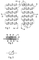
- Such Device is shown in Fig. 1.
- This is preferred as an occupancy sensor 10 formed by known techniques such as e.g. lathering in the upholstery of a vehicle seat can be integrated.
- the occupancy sensor 10 is used by a passenger sitting on the vehicle seat to determine the occupied seat.
- the occupancy sensor 10 has a Variety of active areas 12, which are generally so regularly above the Seating area to be distributed that the seating area in a variety of adjacent Seating areas of a certain size is divided. Is the vehicle seat occupied by a passenger are those below the occupied surface arranged active areas 12 of the occupancy sensor 10 and by determining the number of these stressed active areas e.g. determine the extent of the occupied contact surface.
- the occupancy sensor 10 points in each active area, a switching element 14 which, when the respective assigned seating area is triggered.
- Each switching element 14 is preferred designed such that it has two finite resistance states, i.e. that it has a first finite resistance value if that Switching element 14 is not triggered, and a second resistance value, when the switching element 14 is triggered, the first resistance value is significantly greater than the second resistance value.
- This configuration of the Switching elements 14 with a finite and consequently measurable resistance in non-triggered state enables the switching elements 14 of the occupancy sensor 10 to be connected in series so that they form a resistor chain, which has a measurable finite even when switching elements 14 are not used Exhibits resistance.
- the first and second resistance values the different switching elements 14, the total resistance changes identically the resistance chain linear with the number of triggered switching elements 14, and thus represents a measure of the number of occupied seating areas.
- the Control of the passenger restraint system is then, for example, in one Standard mode switched and the defect of the occupancy sensor 10 possibly indicated by an LED in the dashboard of the vehicle.
- the series connection of the individual switching elements 14 reduces advantageously the number of electrical connections required for the occupancy sensor 10.
- the occupancy sensor 10 only two electrical connections 16 and 18, on the one hand the Total resistance of the resistance chain is measured and on the other hand the Integrity of the switching elements and the wiring can be checked.
- the occupancy sensor 10 shown in FIG. 1 also has three more Connections 20, 22, 24, which divide the resistor chain into four sub-chains, each sub-chain located in a zone of the occupancy sensor 10 is.
- the occupancy sensor 10 is thereby metrologically in four zones divided in which the occupied contact surface by measuring the resistances of the respective partial chains can be determined separately. This enables the distribution of the occupied contact area over the different zones calculate and thus the position of the passenger with respect to the vehicle seat to determine.
- the occupancy sensor 10 is divided into four Zones represent only one possible configuration.
- the occupancy sensor 10 can be made by attaching any number of connections to any number different zones can be divided.
- the subdivision can be divided into Transverse direction as well as in the longitudinal direction of the vehicle seat, or how in both directions in the case shown. The finer the division of the Vehicle seat in one direction, the better the resolution in this direction, the higher the number of needed ones Connections. In practice, the number of different zones of the Vehicle seat a compromise between sufficient resolution and represent the minimum number of connections.
- FIG. 2 shows an advantageous switching element 14 with two resistance states shown in section. It essentially comprises two contact elements 26 and 28, which are arranged at a certain distance from each other.
- the two Contact elements 26 and 28 are formed by a layer 30 made of a resistance material, such as. high-resistance graphite, contacted with each other.
- This Resistor layer 30 determines the resistance of the non-triggered Switching element 14.
- the switching element 14 comprises a low-resistance Tripping element 32, which in a non-triggered switching element 14 in one certain distance from the two contact elements 26, 28 and the resistance layer 30 is arranged.
- the trigger element 32 is electrical highly conductive material such as low-resistance graphite, or a metal such as. Silver made so that its electrical resistance is clear is smaller than the resistance of the resistance layer 30.
- the trigger element 32 When triggering the switching element 14, the trigger element 32 is against the Resistance layer 30 and the contact elements 26 and 28 pressed, the contacted the two contact elements 26 and 28 by the trigger element 32 become.
- the resistance layer 30 is consequently caused by the trigger element 32 bridged and the resistance of the switching element significantly reduced.
- the contacting of the contact elements 26 and 28 by the trigger element 32 does not necessarily have to take place directly, i.e. by direct contact between the contact elements and the trigger element, but that the contacting also through the resistance layer 30 can take place, i.e. substantially perpendicular to the resistance layer 30, if these contact elements 26, 28 e.g. completely covered.
- the layer of resistive material 30 is generally small Thickness (e.g. d ⁇ 25 ⁇ m), so that in connection with relatively large contact areas, the electrical resistance effective when making contact is negligible becomes.
- the switching element 14 sets in principle Component with a variable electrical resistance, however only two discrete resistance values can be assumed.
- the circuit symbol for a variable resistor see Fig. 3).
- the respective contact elements 26, 28 and the resistance layer 30 all Switching elements 14 of the occupancy sensor 10 are preferably on a first one Carrier film 34 of the occupancy sensor 10 applied while the respective Tripping elements 32 are applied to a second carrier film 36, which the is assigned to the first carrier film 34 at a certain distance.
- the application the individual elements are preferably carried out on the respective carrier foils in a screen printing process, with the connecting lines in a first stage between the contact elements 26, 28 simultaneously with the Contact elements are printed.
- the two carrier films 26, 28 by means of a spacer arranged between them 38 glued so that they are arranged at a suitable distance from each other are.
- the spacer 38 can, for example, be double-sided Be made of adhesive film, being in the areas of the actual switching elements 14 each have a recess 40.
- an occupancy sensor 10 have up to 100 or more switching elements 14, for example, each switching element 14 in the non-triggered state has a resistance of about 1 k ⁇ to 5 k ⁇ .
- the resistance ratio V from triggered switching element to non-triggered switching element can depending on the choice of material for the trigger element 32 between 1/1000 ⁇ V ⁇ 1/10.
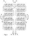
- FIG. 4 shows a second embodiment of an occupancy sensor 10.
- the resistor chain comprising switching elements 14, it comprises a compensation circuit to compensate for the temperature behavior of the switching elements 14.
- the very high temperature fluctuations especially in winter inside the vehicle generally cause significant changes the resistance of the resistance layer 30 of the switching elements 14 while the temperature-related fluctuations of the highly conductive release element 32 are negligible. This means that, above all, the temperature behavior the unoccupied switching elements 14 in the event of temperature fluctuations can lead to falsification of the measurement results. It is consequently advantageous to compensate for the temperature behavior of the resistance layers 30 to be provided.
- Such a compensation circuit then allows also advantageous a compensation of aging-related changes in resistance or of production tolerances such as Tolerances in the layer thickness of the resistance layer 30.
- the occupancy sensor 10 has a compensation circuit, with who performed a resistance reference measurement of the resistance material becomes.
- a compensation circuit has a reference element made of resistance material, its temperature-dependent resistance measured separately and from the evaluation circuit for normalization of the total resistance measured at the respective connections 16-24 of the resistance chain is used.
- the compensation circuit comprises a plurality of reference elements 42, each of which assigned to a corresponding switching element 14 in such a way adjacent is that in each seating area of the vehicle seat there is a switching element 14 and a reference element 42 is arranged.
- the reference elements 42 By arranging the reference elements 42 in the immediate vicinity of the assigned switching elements 14 it is guaranteed that the mechanical and thermal stresses of switching element 14 and associated reference element 42 almost are identical, so that the best possible compensation can take place. Since the resistance layer 48 of the reference element 42 in the immediate Proximity of the resistance layer 30 of the switching element 14 can be printed moreover, the influence of the varying printing thickness of the layers can be eliminated.
- the reference elements are preferred, except for the trigger element 32 are of the same construction as the switching elements 14 (see FIG. 5). Every reference element accordingly comprises two contact elements 44, 46 on the carrier film 34 are arranged at a certain distance from each other and by a layer of resistance material 48 is electrically contacted with one another are.
- the dimensions of the contact elements 44, 46 and the resistance layer 48 correspond to the dimensions of the contact elements 26, 28 or the resistance layer 30, so that the electrical resistance of the reference element 42 the electrical resistance of the non-triggered switching element 14 corresponds.
- the switching elements 14 have the reference elements 42, however, no trigger element 32 on the second Carrier film 36, i.e. the resistance layer 48 cannot pass through a trigger element 32 can be bridged.
- the reference elements 42 are accordingly are designed as simple reference resistors and are indicated by the circuit symbol shown for a resistor (see Fig. 6). It should be noted that due to the absence of the trigger element 32 of the spacer 38 in Area of the reference elements 42 does not necessarily have a cutout 40 must have. Such a cutout 40 is preferably provided, however, so that similar to the switching elements 14, a ventilated cavity is formed and the resistance layer 48 under the same conditions as the resistive layer 30 is exposed.
- the contact elements 26, 28 of the switching elements 14 and the contact elements 44, 46 of the reference elements 42 preferably in the same operation and from the same Material printed on the carrier film 34.
- the resistance layers 30 and 48 made in one operation from the same material. This ensures that the resistance values of the switching elements 14 and the reference elements 42 are the same and the same temperature behavior and have aging behavior.
- the individual reference elements 42 are in series switched and form a reference resistor chain corresponding to the resistor chain out.
- This reference resistance chain preferably has the same number of connections 50-58 as the resistor chain, the Reference resistance chain is divided into corresponding sub-chains.
- the Temperature or aging compensation of the occupancy sensor 10 can consequently how the determination of the contact surface is carried out zone by zone, so that the determination of the distribution of the contact surface is corrected accordingly can be.
- the compensation of the temperature or aging behavior is carried out sequentially, ie the resistance values of the resistance chain and the reference chain are first measured in succession at the corresponding connections. The determined values of the resistor chain are then normalized to the reference values in the evaluation circuit.
- each resistance chain is connected to the corresponding reference chain as a voltage divider. Such an interconnection is shown in FIG. 7, only one switching element 14 and one reference element 42 being shown in each case.
- An input voltage U e is applied to the input of the circuit and the resulting output voltage U a is measured at the connection point between the resistor chain and the reference chain.
- the output voltage determined in this way then provides direct information about the compensated resistance of the resistor chain. A subsequent standardization of the measured values is no longer necessary.
- several voltage dividers are advantageously supplied with the same input voltage U e to reduce the number of connections required (see FIG. 8). The number of connections required for the sensor is therefore only two more than the number of resistor chains / reference chain pairs.
Landscapes
- Engineering & Computer Science (AREA)
- Mechanical Engineering (AREA)
- Aviation & Aerospace Engineering (AREA)
- Transportation (AREA)
- Physics & Mathematics (AREA)
- Mathematical Physics (AREA)
- Theoretical Computer Science (AREA)
- Computer Networks & Wireless Communication (AREA)
- General Physics & Mathematics (AREA)
- Seats For Vehicles (AREA)
- Air Bags (AREA)
Applications Claiming Priority (2)
| Application Number | Priority Date | Filing Date | Title |
|---|---|---|---|
| LU90106A LU90106B1 (de) | 1997-07-18 | 1997-07-18 | Verfahren und Vorrichtung zum Erfassen verschiedener Parameter einer auf einer Unterlage sitzenden Person |
| LU90106 | 1997-07-18 |
Publications (2)
| Publication Number | Publication Date |
|---|---|
| EP0891898A1 true EP0891898A1 (fr) | 1999-01-20 |
| EP0891898B1 EP0891898B1 (fr) | 2002-11-06 |
Family
ID=19731701
Family Applications (1)
| Application Number | Title | Priority Date | Filing Date |
|---|---|---|---|
| EP98109150A Expired - Lifetime EP0891898B1 (fr) | 1997-07-18 | 1998-05-20 | Méthode et appareillage d' enregistrement de différents paramètres d' une personne assise sur un support |
Country Status (4)
| Country | Link |
|---|---|
| EP (1) | EP0891898B1 (fr) |
| DE (1) | DE59806152D1 (fr) |
| ES (1) | ES2186942T3 (fr) |
| LU (1) | LU90106B1 (fr) |
Cited By (20)
| Publication number | Priority date | Publication date | Assignee | Title |
|---|---|---|---|---|
| LU90361B1 (de) | 1999-03-02 | 2000-09-05 | Iee Sarl | Vorrichtung zum Erfassen der Sitzposition einer in einem Sitz einsitzenden Person |
| WO2003089276A1 (fr) * | 2002-04-19 | 2003-10-30 | Bayerische Motoren Werke Aktiengesellschaft | Procede de detection de l'occupation d'un siege de vehicule |
| EP1457391A1 (fr) | 2003-03-10 | 2004-09-15 | IEE INTERNATIONAL ELECTRONICS & ENGINEERING S.A. | Système de détection de l'occupation d'un siège |
| EP1470968A1 (fr) * | 2003-04-23 | 2004-10-27 | Delphi Technologies, Inc. | Système de détection d'un occupant pour véhicule |
| EP1492136A1 (fr) * | 2003-06-23 | 2004-12-29 | IEE International Electronics & Engineering S.A.R.L. | Capteur de pression du type à feuilles |
| US6889129B2 (en) | 2002-05-24 | 2005-05-03 | Denso Corporation | Vehicle seat occupant classifying method and apparatus based on a support vector machine |
| DE102004015408A1 (de) * | 2004-03-26 | 2005-10-13 | Bayerische Motoren Werke Ag | Sitzbelegungsdrucksensor |
| WO2006058573A1 (fr) * | 2004-11-29 | 2006-06-08 | Bayerische Motoren Werke Aktiengesellschaft | Capteur de pression d'occupation de siege |
| DE102005003882A1 (de) * | 2005-01-24 | 2006-07-27 | Volkswagen Ag | Anordnung einer Vorrichtung zur Sitzbelegungserkennung in einem Kraftfahrzeugsitz |
| EP1688314A1 (fr) * | 2005-02-04 | 2006-08-09 | IEE INTERNATIONAL ELECTRONICS & ENGINEERING S.A. | Détecteur de pression de type feuille et procédé d'évaluation de la réponse du détecteur |
| DE102006019712A1 (de) * | 2006-04-27 | 2007-11-08 | Siemens Ag | Verfahren und Vorrichtung zur Klassifikation von Insassen in einem Verkehrsmittel |
| DE102006056920A1 (de) * | 2006-12-02 | 2008-06-05 | GM Global Technology Operations, Inc., Detroit | Sensoreinrichtung für den Sitz eines Transportmittels |
| DE102007011277A1 (de) * | 2007-03-08 | 2008-09-11 | Volkswagen Ag | Verfahren und Vorrichtung zur Sitzüberwachung |
| US7708101B2 (en) | 2005-01-24 | 2010-05-04 | F.S. Fehrer Automotive Gmbh | Motor vehicle seat having occupant detector |
| EP1800942A4 (fr) * | 2004-08-27 | 2011-06-08 | Aisin Seiki | Dispositif de detection de l'etat d'un siege et dispositif d'ajustement de direction d'eclairage pour phare de vehicule |
| US8013264B2 (en) | 2003-05-20 | 2011-09-06 | Fujikura Ltd. | Seating detection switch |
| US8049520B2 (en) | 2005-11-22 | 2011-11-01 | Iee International Electronics & Engineering S.A. | System for capacitive detection of a seat occupancy |
| US8115648B2 (en) | 2003-06-23 | 2012-02-14 | Iee International Electronics & Engineering S.A. | Seat occupancy sensor |
| DE102011107008A1 (de) | 2011-07-09 | 2013-01-10 | Volkswagen Aktiengesellschaft | Körpermassenabhängige Sitzheizungsregelung eines Sitzteiles und einer Rückenlehne eines Fahrzeugsitzes |
| EP1833702B2 (fr) † | 2005-01-03 | 2016-08-17 | Iee International Electronics & Engineering S.A. | Tapis de detection comprenant deux niveau de commutation |
Families Citing this family (3)
| Publication number | Priority date | Publication date | Assignee | Title |
|---|---|---|---|---|
| US7641229B2 (en) | 2003-06-25 | 2010-01-05 | Autoliv Asp, Inc. | Seat control structure for occupant classification systems |
| JP2005069968A (ja) * | 2003-08-27 | 2005-03-17 | Aisin Seiki Co Ltd | 着座検出装置 |
| DE102005053744B3 (de) * | 2005-11-10 | 2006-12-28 | Lear Corp., Southfield | Verfahren zur Bestimmung eines äquivalenten Wertes für einen ausgefallenen Sensor in einem Fahrzeugsitz mit einem Besetzungsabfühlsystem |
Citations (4)
| Publication number | Priority date | Publication date | Assignee | Title |
|---|---|---|---|---|
| DE4212018A1 (de) * | 1991-04-09 | 1992-10-15 | Trw Vehicle Safety Systems | Insassenabfuehlvorrichtung |
| US5474327A (en) * | 1995-01-10 | 1995-12-12 | Delco Electronics Corporation | Vehicle occupant restraint with seat pressure sensor |
| WO1997010115A1 (fr) * | 1995-09-12 | 1997-03-20 | I.E.E. International Electronics & Engineering S.A.R.L. | Dispositif de detection pour des sieges de vehicules |
| FR2744548A1 (fr) * | 1996-02-07 | 1997-08-08 | Leteurtre Jean | Systeme et procede de detection de presence d'une personne assise dans un habitacle, notamment un passager d'un vehicule automobile |
Family Cites Families (2)
| Publication number | Priority date | Publication date | Assignee | Title |
|---|---|---|---|---|
| GB2225660A (en) * | 1988-12-05 | 1990-06-06 | Autoliv Dev | A trigger circuit arrangement for a vehicle safety device, eg a crash bag |
| US4958851A (en) * | 1989-05-01 | 1990-09-25 | Automotive Systems Laboratory, Inc. | Air bag firing circuit |
-
1997
- 1997-07-18 LU LU90106A patent/LU90106B1/xx active
-
1998
- 1998-05-20 DE DE59806152T patent/DE59806152D1/de not_active Expired - Fee Related
- 1998-05-20 ES ES98109150T patent/ES2186942T3/es not_active Expired - Lifetime
- 1998-05-20 EP EP98109150A patent/EP0891898B1/fr not_active Expired - Lifetime
Patent Citations (5)
| Publication number | Priority date | Publication date | Assignee | Title |
|---|---|---|---|---|
| DE4212018A1 (de) * | 1991-04-09 | 1992-10-15 | Trw Vehicle Safety Systems | Insassenabfuehlvorrichtung |
| US5232243A (en) | 1991-04-09 | 1993-08-03 | Trw Vehicle Safety Systems Inc. | Occupant sensing apparatus |
| US5474327A (en) * | 1995-01-10 | 1995-12-12 | Delco Electronics Corporation | Vehicle occupant restraint with seat pressure sensor |
| WO1997010115A1 (fr) * | 1995-09-12 | 1997-03-20 | I.E.E. International Electronics & Engineering S.A.R.L. | Dispositif de detection pour des sieges de vehicules |
| FR2744548A1 (fr) * | 1996-02-07 | 1997-08-08 | Leteurtre Jean | Systeme et procede de detection de presence d'une personne assise dans un habitacle, notamment un passager d'un vehicule automobile |
Cited By (36)
| Publication number | Priority date | Publication date | Assignee | Title |
|---|---|---|---|---|
| LU90361B1 (de) | 1999-03-02 | 2000-09-05 | Iee Sarl | Vorrichtung zum Erfassen der Sitzposition einer in einem Sitz einsitzenden Person |
| WO2003089276A1 (fr) * | 2002-04-19 | 2003-10-30 | Bayerische Motoren Werke Aktiengesellschaft | Procede de detection de l'occupation d'un siege de vehicule |
| US7567184B2 (en) | 2002-04-19 | 2009-07-28 | Bayerische Motoren Werke Aktiengesellschaft | Method for establishing the occupation of a vehicle seat |
| CN100402351C (zh) * | 2002-04-19 | 2008-07-16 | 宝马股份公司 | 用于确定车座占用情况的方法 |
| US6889129B2 (en) | 2002-05-24 | 2005-05-03 | Denso Corporation | Vehicle seat occupant classifying method and apparatus based on a support vector machine |
| EP1457391A1 (fr) | 2003-03-10 | 2004-09-15 | IEE INTERNATIONAL ELECTRONICS & ENGINEERING S.A. | Système de détection de l'occupation d'un siège |
| WO2004080766A1 (fr) * | 2003-03-10 | 2004-09-23 | Iee International Electronics & Engineering S.A. | Systeme de detection d'occupation de siege |
| US7181324B2 (en) | 2003-04-23 | 2007-02-20 | Delphi Technologies, Inc. | Occupant recognition system for vehicles |
| EP1470968A1 (fr) * | 2003-04-23 | 2004-10-27 | Delphi Technologies, Inc. | Système de détection d'un occupant pour véhicule |
| US8053692B2 (en) | 2003-05-20 | 2011-11-08 | Fujikura Ltd. | Seating detection switch |
| US8013264B2 (en) | 2003-05-20 | 2011-09-06 | Fujikura Ltd. | Seating detection switch |
| US8258417B2 (en) | 2003-05-20 | 2012-09-04 | Fujikura Ltd. | Seating detection switch |
| US8044311B2 (en) | 2003-05-20 | 2011-10-25 | Fujikura Ltd. | Seating detection switch |
| US8115648B2 (en) | 2003-06-23 | 2012-02-14 | Iee International Electronics & Engineering S.A. | Seat occupancy sensor |
| EP1492136A1 (fr) * | 2003-06-23 | 2004-12-29 | IEE International Electronics & Engineering S.A.R.L. | Capteur de pression du type à feuilles |
| US7343807B2 (en) | 2003-06-23 | 2008-03-18 | Iee International Electronics & Engineering S.A. | Pressure sensor in the form of a film |
| CN100458984C (zh) * | 2003-06-23 | 2009-02-04 | Iee国际电子及工程股份有限公司 | 薄膜形式的压力传感器 |
| WO2005001864A1 (fr) * | 2003-06-23 | 2005-01-06 | Iee International Electronics & Engineering S.A. | Capteur de pression dont la structure comporte des feuilles |
| DE102004015408B4 (de) * | 2004-03-26 | 2015-08-06 | Bayerische Motoren Werke Aktiengesellschaft | Sitzbelegungsdrucksensor |
| DE102004015408A1 (de) * | 2004-03-26 | 2005-10-13 | Bayerische Motoren Werke Ag | Sitzbelegungsdrucksensor |
| EP1800942A4 (fr) * | 2004-08-27 | 2011-06-08 | Aisin Seiki | Dispositif de detection de l'etat d'un siege et dispositif d'ajustement de direction d'eclairage pour phare de vehicule |
| WO2006058573A1 (fr) * | 2004-11-29 | 2006-06-08 | Bayerische Motoren Werke Aktiengesellschaft | Capteur de pression d'occupation de siege |
| EP1833702B2 (fr) † | 2005-01-03 | 2016-08-17 | Iee International Electronics & Engineering S.A. | Tapis de detection comprenant deux niveau de commutation |
| DE102005003882B4 (de) * | 2005-01-24 | 2015-03-05 | Volkswagen Ag | Anordnung einer Vorrichtung zur Sitzbelegungserkennung in einem Kraftfahrzeugsitz |
| US7708101B2 (en) | 2005-01-24 | 2010-05-04 | F.S. Fehrer Automotive Gmbh | Motor vehicle seat having occupant detector |
| DE102005003882A1 (de) * | 2005-01-24 | 2006-07-27 | Volkswagen Ag | Anordnung einer Vorrichtung zur Sitzbelegungserkennung in einem Kraftfahrzeugsitz |
| EP1688314A1 (fr) * | 2005-02-04 | 2006-08-09 | IEE INTERNATIONAL ELECTRONICS & ENGINEERING S.A. | Détecteur de pression de type feuille et procédé d'évaluation de la réponse du détecteur |
| WO2006081882A1 (fr) * | 2005-02-04 | 2006-08-10 | Iee International Electronics & Engineering S.A. | Capteur de pression de type film et procede d'evaluation de la reponse du capteur |
| US8049520B2 (en) | 2005-11-22 | 2011-11-01 | Iee International Electronics & Engineering S.A. | System for capacitive detection of a seat occupancy |
| DE102006019712A1 (de) * | 2006-04-27 | 2007-11-08 | Siemens Ag | Verfahren und Vorrichtung zur Klassifikation von Insassen in einem Verkehrsmittel |
| DE102006019712B4 (de) * | 2006-04-27 | 2008-03-06 | Siemens Ag | Verfahren und Vorrichtung zur Klassifikation von Insassen in einem Verkehrsmittel |
| DE102006056920A1 (de) * | 2006-12-02 | 2008-06-05 | GM Global Technology Operations, Inc., Detroit | Sensoreinrichtung für den Sitz eines Transportmittels |
| DE102006056920B4 (de) * | 2006-12-02 | 2019-07-04 | GM Global Technology Operations LLC (n. d. Ges. d. Staates Delaware) | Sensoreinrichtung für den Sitz eines Transportmittels |
| DE102007011277A1 (de) * | 2007-03-08 | 2008-09-11 | Volkswagen Ag | Verfahren und Vorrichtung zur Sitzüberwachung |
| DE102007011277B4 (de) * | 2007-03-08 | 2019-10-10 | Volkswagen Ag | Verfahren und Vorrichtung zur Sitzüberwachung |
| DE102011107008A1 (de) | 2011-07-09 | 2013-01-10 | Volkswagen Aktiengesellschaft | Körpermassenabhängige Sitzheizungsregelung eines Sitzteiles und einer Rückenlehne eines Fahrzeugsitzes |
Also Published As
| Publication number | Publication date |
|---|---|
| EP0891898B1 (fr) | 2002-11-06 |
| LU90106B1 (de) | 1999-01-19 |
| ES2186942T3 (es) | 2003-05-16 |
| DE59806152D1 (de) | 2002-12-12 |
Similar Documents
| Publication | Publication Date | Title |
|---|---|---|
| EP0891898B1 (fr) | Méthode et appareillage d' enregistrement de différents paramètres d' une personne assise sur un support | |
| DE69707906T2 (de) | Verfahren und Vorrichtung zur Bestimmung von verschiedenen Parametern einer auf einen Sitz sitzenden Person | |
| DE602004006894T2 (de) | Vorrichtung zur klassifizierung von sitzbelegung | |
| DE4406897C1 (de) | Vorrichtung zur Sitzbelegungserkennung für ein Kraftfahrzeug | |
| DE102006002919B4 (de) | Kapazitiver Sensor und Insassenerfassungssystem | |
| DE602004009029T2 (de) | Fahrzeugbelegungserfassungssystem | |
| EP0476356B1 (fr) | Dispositif pour surveiller l'occuparion d'un siège de véhicules automobiles | |
| DE102011006344B4 (de) | Insassenmesssystem | |
| EP1636071B1 (fr) | Capteur permettant de detecter l'occupation d'un siege | |
| DE60029144T2 (de) | Vorrichtung zur Heizung eines Fahrzeugsitzes und Verfahren zur Herstellung einer solchen Vorrichtung | |
| DE60112595T2 (de) | System zur gewichtsklassifizierung | |
| DE10043909A1 (de) | Verfahren zum Bestimmen eines Objekts auf einem Fahrzeugsitz sowie Verfahren zum Bestimmen der Gassackentfaltungsbetriebsweise | |
| EP1704074B1 (fr) | Systeme de commande destine a la reconnaissance de l'occupation d'un siege et a l'avertissement de ceinture d'un vehicule automobile | |
| DE19900842A1 (de) | Insassenerfassungssystem | |
| EP2127957B1 (fr) | Système d'alerte pour ceinture de sécurité | |
| DE20014200U1 (de) | Sensoranordnung | |
| DE69602539T2 (de) | Detektor für fahrzeugsitze | |
| DE112018003062T5 (de) | Kapazitives Insassenerkennungssystem mit verbesserter Isofix-unterscheidung | |
| DE102012025037C5 (de) | Verfahren zur kapazitiven Sitzbelegungserkennung für Fahrzeugsitze | |
| DE102005027041B3 (de) | Vorrichtung und Verfahren zur Sitzbelegungserkennung | |
| EP2535227B1 (fr) | Procédé de détection de l'occupation d'un siège et siège avec un dispositif de détection d'occupation | |
| EP1379849B1 (fr) | Circuit comprenant plusieurs elements de detection a interconnexion matricielle | |
| DE102005001690A1 (de) | Fahrzeuginsassen-Detektionssystem | |
| EP1491408A1 (fr) | Détecteur d'occupation de siège | |
| EP1474669B1 (fr) | Procede permettant de determiner la resistance electrique d'un cable d'alimentation electrique d'elements de detection et ensemble de detection |
Legal Events
| Date | Code | Title | Description |
|---|---|---|---|
| PUAI | Public reference made under article 153(3) epc to a published international application that has entered the european phase |
Free format text: ORIGINAL CODE: 0009012 |
|
| AK | Designated contracting states |
Kind code of ref document: A1 Designated state(s): DE ES FR GB IT SE |
|
| AX | Request for extension of the european patent |
Free format text: AL;LT;LV;MK;RO;SI |
|
| 17P | Request for examination filed |
Effective date: 19990618 |
|
| AKX | Designation fees paid |
Free format text: DE ES FR GB IT SE |
|
| RBV | Designated contracting states (corrected) |
Designated state(s): DE ES FR GB IT SE |
|
| 17Q | First examination report despatched |
Effective date: 20010319 |
|
| GRAG | Despatch of communication of intention to grant |
Free format text: ORIGINAL CODE: EPIDOS AGRA |
|
| GRAG | Despatch of communication of intention to grant |
Free format text: ORIGINAL CODE: EPIDOS AGRA |
|
| GRAH | Despatch of communication of intention to grant a patent |
Free format text: ORIGINAL CODE: EPIDOS IGRA |
|
| GRAH | Despatch of communication of intention to grant a patent |
Free format text: ORIGINAL CODE: EPIDOS IGRA |
|
| GRAA | (expected) grant |
Free format text: ORIGINAL CODE: 0009210 |
|
| AK | Designated contracting states |
Kind code of ref document: B1 Designated state(s): DE ES FR GB IT SE |
|
| REG | Reference to a national code |
Ref country code: GB Ref legal event code: FG4D Free format text: NOT ENGLISH |
|
| REF | Corresponds to: |
Ref document number: 59806152 Country of ref document: DE Date of ref document: 20021212 |
|
| RAP2 | Party data changed (patent owner data changed or rights of a patent transferred) |
Owner name: IEE INTERNATIONAL ELECTRONICS & ENGINEERING S. |
|
| ET | Fr: translation filed | ||
| REG | Reference to a national code |
Ref country code: ES Ref legal event code: FG2A Ref document number: 2186942 Country of ref document: ES Kind code of ref document: T3 |
|
| GBT | Gb: translation of ep patent filed (gb section 77(6)(a)/1977) |
Effective date: 20030424 |
|
| PLBE | No opposition filed within time limit |
Free format text: ORIGINAL CODE: 0009261 |
|
| STAA | Information on the status of an ep patent application or granted ep patent |
Free format text: STATUS: NO OPPOSITION FILED WITHIN TIME LIMIT |
|
| 26N | No opposition filed |
Effective date: 20030807 |
|
| PGFP | Annual fee paid to national office [announced via postgrant information from national office to epo] |
Ref country code: FR Payment date: 20050413 Year of fee payment: 8 |
|
| PGFP | Annual fee paid to national office [announced via postgrant information from national office to epo] |
Ref country code: GB Payment date: 20050420 Year of fee payment: 8 |
|
| PGFP | Annual fee paid to national office [announced via postgrant information from national office to epo] |
Ref country code: SE Payment date: 20050519 Year of fee payment: 8 |
|
| PGFP | Annual fee paid to national office [announced via postgrant information from national office to epo] |
Ref country code: ES Payment date: 20050609 Year of fee payment: 8 |
|
| PG25 | Lapsed in a contracting state [announced via postgrant information from national office to epo] |
Ref country code: GB Free format text: LAPSE BECAUSE OF NON-PAYMENT OF DUE FEES Effective date: 20060520 |
|
| PG25 | Lapsed in a contracting state [announced via postgrant information from national office to epo] |
Ref country code: SE Free format text: LAPSE BECAUSE OF NON-PAYMENT OF DUE FEES Effective date: 20060521 |
|
| PG25 | Lapsed in a contracting state [announced via postgrant information from national office to epo] |
Ref country code: ES Free format text: LAPSE BECAUSE OF NON-PAYMENT OF DUE FEES Effective date: 20060522 |
|
| PGFP | Annual fee paid to national office [announced via postgrant information from national office to epo] |
Ref country code: IT Payment date: 20060531 Year of fee payment: 9 |
|
| EUG | Se: european patent has lapsed | ||
| GBPC | Gb: european patent ceased through non-payment of renewal fee |
Effective date: 20060520 |
|
| REG | Reference to a national code |
Ref country code: FR Ref legal event code: ST Effective date: 20070131 |
|
| REG | Reference to a national code |
Ref country code: ES Ref legal event code: FD2A Effective date: 20060522 |
|
| PG25 | Lapsed in a contracting state [announced via postgrant information from national office to epo] |
Ref country code: FR Free format text: LAPSE BECAUSE OF NON-PAYMENT OF DUE FEES Effective date: 20060531 |
|
| PGFP | Annual fee paid to national office [announced via postgrant information from national office to epo] |
Ref country code: DE Payment date: 20080312 Year of fee payment: 11 |
|
| PG25 | Lapsed in a contracting state [announced via postgrant information from national office to epo] |
Ref country code: IT Free format text: LAPSE BECAUSE OF NON-PAYMENT OF DUE FEES Effective date: 20070520 |
|
| PG25 | Lapsed in a contracting state [announced via postgrant information from national office to epo] |
Ref country code: DE Free format text: LAPSE BECAUSE OF NON-PAYMENT OF DUE FEES Effective date: 20091201 |