EP0892091A1 - Creuset de support en graphite présentant une faible concentration en impurités de calcium et sa mise en oeuvre dans la production de monocristaux de silicium - Google Patents
Creuset de support en graphite présentant une faible concentration en impurités de calcium et sa mise en oeuvre dans la production de monocristaux de silicium Download PDFInfo
- Publication number
- EP0892091A1 EP0892091A1 EP97304874A EP97304874A EP0892091A1 EP 0892091 A1 EP0892091 A1 EP 0892091A1 EP 97304874 A EP97304874 A EP 97304874A EP 97304874 A EP97304874 A EP 97304874A EP 0892091 A1 EP0892091 A1 EP 0892091A1
- Authority
- EP
- European Patent Office
- Prior art keywords
- support vessel
- silica container
- graphite
- silicon
- silica
- Prior art date
- Legal status (The legal status is an assumption and is not a legal conclusion. Google has not performed a legal analysis and makes no representation as to the accuracy of the status listed.)
- Withdrawn
Links
- OKTJSMMVPCPJKN-UHFFFAOYSA-N Carbon Chemical compound [C] OKTJSMMVPCPJKN-UHFFFAOYSA-N 0.000 title claims abstract description 98
- 229910002804 graphite Inorganic materials 0.000 title claims abstract description 91
- 239000010439 graphite Substances 0.000 title claims abstract description 91
- 229910021421 monocrystalline silicon Inorganic materials 0.000 title claims abstract description 45
- 239000011575 calcium Substances 0.000 title claims abstract description 32
- OYPRJOBELJOOCE-UHFFFAOYSA-N Calcium Chemical compound [Ca] OYPRJOBELJOOCE-UHFFFAOYSA-N 0.000 title claims abstract description 31
- 229910052791 calcium Inorganic materials 0.000 title claims abstract description 31
- 238000004519 manufacturing process Methods 0.000 title claims abstract description 20
- 239000012535 impurity Substances 0.000 title abstract description 20
- VYPSYNLAJGMNEJ-UHFFFAOYSA-N Silicium dioxide Chemical compound O=[Si]=O VYPSYNLAJGMNEJ-UHFFFAOYSA-N 0.000 claims abstract description 230
- 239000000377 silicon dioxide Substances 0.000 claims abstract description 102
- 238000000034 method Methods 0.000 claims abstract description 41
- XUIMIQQOPSSXEZ-UHFFFAOYSA-N Silicon Chemical compound [Si] XUIMIQQOPSSXEZ-UHFFFAOYSA-N 0.000 claims abstract description 36
- 229910052710 silicon Inorganic materials 0.000 claims abstract description 35
- 239000010703 silicon Substances 0.000 claims abstract description 35
- 229910052784 alkaline earth metal Inorganic materials 0.000 claims abstract description 23
- 150000001342 alkaline earth metals Chemical class 0.000 claims abstract description 19
- 229910052783 alkali metal Inorganic materials 0.000 claims abstract description 14
- 150000001340 alkali metals Chemical class 0.000 claims abstract description 14
- 229910021420 polycrystalline silicon Inorganic materials 0.000 claims description 29
- 230000001186 cumulative effect Effects 0.000 claims description 9
- 230000015572 biosynthetic process Effects 0.000 claims description 7
- 239000000155 melt Substances 0.000 claims description 5
- 238000013459 approach Methods 0.000 claims description 4
- 239000013078 crystal Substances 0.000 abstract description 31
- 238000004031 devitrification Methods 0.000 abstract description 27
- 238000002425 crystallisation Methods 0.000 abstract description 4
- 230000008025 crystallization Effects 0.000 abstract description 4
- 238000010438 heat treatment Methods 0.000 abstract description 3
- 229910052799 carbon Inorganic materials 0.000 description 11
- 230000007423 decrease Effects 0.000 description 9
- 235000012239 silicon dioxide Nutrition 0.000 description 6
- 239000003513 alkali Substances 0.000 description 5
- 238000000576 coating method Methods 0.000 description 5
- DGAQECJNVWCQMB-PUAWFVPOSA-M Ilexoside XXIX Chemical compound C[C@@H]1CC[C@@]2(CC[C@@]3(C(=CC[C@H]4[C@]3(CC[C@@H]5[C@@]4(CC[C@@H](C5(C)C)OS(=O)(=O)[O-])C)C)[C@@H]2[C@]1(C)O)C)C(=O)O[C@H]6[C@@H]([C@H]([C@@H]([C@H](O6)CO)O)O)O.[Na+] DGAQECJNVWCQMB-PUAWFVPOSA-M 0.000 description 4
- WHXSMMKQMYFTQS-UHFFFAOYSA-N Lithium Chemical compound [Li] WHXSMMKQMYFTQS-UHFFFAOYSA-N 0.000 description 4
- FYYHWMGAXLPEAU-UHFFFAOYSA-N Magnesium Chemical compound [Mg] FYYHWMGAXLPEAU-UHFFFAOYSA-N 0.000 description 4
- ZLMJMSJWJFRBEC-UHFFFAOYSA-N Potassium Chemical compound [K] ZLMJMSJWJFRBEC-UHFFFAOYSA-N 0.000 description 4
- 239000002585 base Substances 0.000 description 4
- 230000002706 hydrostatic effect Effects 0.000 description 4
- 229910052744 lithium Inorganic materials 0.000 description 4
- 229910052749 magnesium Inorganic materials 0.000 description 4
- 239000011777 magnesium Substances 0.000 description 4
- 229910052700 potassium Inorganic materials 0.000 description 4
- 239000011591 potassium Substances 0.000 description 4
- 238000000746 purification Methods 0.000 description 4
- 229910052708 sodium Inorganic materials 0.000 description 4
- 239000011734 sodium Substances 0.000 description 4
- 229910052712 strontium Inorganic materials 0.000 description 4
- CIOAGBVUUVVLOB-UHFFFAOYSA-N strontium atom Chemical compound [Sr] CIOAGBVUUVVLOB-UHFFFAOYSA-N 0.000 description 4
- 238000010923 batch production Methods 0.000 description 3
- 239000011230 binding agent Substances 0.000 description 3
- 229910002026 crystalline silica Inorganic materials 0.000 description 3
- 230000001627 detrimental effect Effects 0.000 description 3
- 230000000694 effects Effects 0.000 description 3
- 239000000945 filler Substances 0.000 description 3
- 238000011065 in-situ storage Methods 0.000 description 3
- 239000000463 material Substances 0.000 description 3
- NJPPVKZQTLUDBO-UHFFFAOYSA-N novaluron Chemical compound C1=C(Cl)C(OC(F)(F)C(OC(F)(F)F)F)=CC=C1NC(=O)NC(=O)C1=C(F)C=CC=C1F NJPPVKZQTLUDBO-UHFFFAOYSA-N 0.000 description 3
- 239000010453 quartz Substances 0.000 description 3
- 238000011282 treatment Methods 0.000 description 3
- XKRFYHLGVUSROY-UHFFFAOYSA-N Argon Chemical compound [Ar] XKRFYHLGVUSROY-UHFFFAOYSA-N 0.000 description 2
- 238000006243 chemical reaction Methods 0.000 description 2
- 230000003749 cleanliness Effects 0.000 description 2
- 238000011109 contamination Methods 0.000 description 2
- 230000004907 flux Effects 0.000 description 2
- 239000005350 fused silica glass Substances 0.000 description 2
- 239000007789 gas Substances 0.000 description 2
- 238000011068 loading method Methods 0.000 description 2
- 238000002844 melting Methods 0.000 description 2
- 230000008018 melting Effects 0.000 description 2
- 229910052751 metal Inorganic materials 0.000 description 2
- 239000002184 metal Substances 0.000 description 2
- 150000002739 metals Chemical class 0.000 description 2
- 230000006911 nucleation Effects 0.000 description 2
- 238000010899 nucleation Methods 0.000 description 2
- 238000010926 purge Methods 0.000 description 2
- 229910052905 tridymite Inorganic materials 0.000 description 2
- 230000001154 acute effect Effects 0.000 description 1
- 230000002411 adverse Effects 0.000 description 1
- 229910052786 argon Inorganic materials 0.000 description 1
- 238000003763 carbonization Methods 0.000 description 1
- 239000005539 carbonized material Substances 0.000 description 1
- 239000011294 coal tar pitch Substances 0.000 description 1
- 239000011248 coating agent Substances 0.000 description 1
- 239000000356 contaminant Substances 0.000 description 1
- 238000010924 continuous production Methods 0.000 description 1
- 229910052906 cristobalite Inorganic materials 0.000 description 1
- 230000003247 decreasing effect Effects 0.000 description 1
- 230000007547 defect Effects 0.000 description 1
- 238000010586 diagram Methods 0.000 description 1
- 238000009792 diffusion process Methods 0.000 description 1
- 238000007598 dipping method Methods 0.000 description 1
- 238000005868 electrolysis reaction Methods 0.000 description 1
- 238000005516 engineering process Methods 0.000 description 1
- 238000001125 extrusion Methods 0.000 description 1
- 239000007770 graphite material Substances 0.000 description 1
- 238000005087 graphitization Methods 0.000 description 1
- 229910052736 halogen Inorganic materials 0.000 description 1
- 150000002367 halogens Chemical class 0.000 description 1
- 239000011261 inert gas Substances 0.000 description 1
- 238000004898 kneading Methods 0.000 description 1
- 239000007788 liquid Substances 0.000 description 1
- 238000004377 microelectronic Methods 0.000 description 1
- 238000002156 mixing Methods 0.000 description 1
- 239000000203 mixture Substances 0.000 description 1
- 238000000465 moulding Methods 0.000 description 1
- 239000002245 particle Substances 0.000 description 1
- 239000002006 petroleum coke Substances 0.000 description 1
- 239000000843 powder Substances 0.000 description 1
- 238000002360 preparation method Methods 0.000 description 1
- 230000001737 promoting effect Effects 0.000 description 1
- 239000002994 raw material Substances 0.000 description 1
- 238000007670 refining Methods 0.000 description 1
- 238000007665 sagging Methods 0.000 description 1
- 230000009466 transformation Effects 0.000 description 1
- 229910052724 xenon Inorganic materials 0.000 description 1
- FHNFHKCVQCLJFQ-UHFFFAOYSA-N xenon atom Chemical compound [Xe] FHNFHKCVQCLJFQ-UHFFFAOYSA-N 0.000 description 1
Images


Classifications
-
- C—CHEMISTRY; METALLURGY
- C30—CRYSTAL GROWTH
- C30B—SINGLE-CRYSTAL GROWTH; UNIDIRECTIONAL SOLIDIFICATION OF EUTECTIC MATERIAL OR UNIDIRECTIONAL DEMIXING OF EUTECTOID MATERIAL; REFINING BY ZONE-MELTING OF MATERIAL; PRODUCTION OF A HOMOGENEOUS POLYCRYSTALLINE MATERIAL WITH DEFINED STRUCTURE; SINGLE CRYSTALS OR HOMOGENEOUS POLYCRYSTALLINE MATERIAL WITH DEFINED STRUCTURE; AFTER-TREATMENT OF SINGLE CRYSTALS OR A HOMOGENEOUS POLYCRYSTALLINE MATERIAL WITH DEFINED STRUCTURE; APPARATUS THEREFOR
- C30B15/00—Single-crystal growth by pulling from a melt, e.g. Czochralski method
- C30B15/10—Crucibles or containers for supporting the melt
-
- C—CHEMISTRY; METALLURGY
- C04—CEMENTS; CONCRETE; ARTIFICIAL STONE; CERAMICS; REFRACTORIES
- C04B—LIME, MAGNESIA; SLAG; CEMENTS; COMPOSITIONS THEREOF, e.g. MORTARS, CONCRETE OR LIKE BUILDING MATERIALS; ARTIFICIAL STONE; CERAMICS; REFRACTORIES; TREATMENT OF NATURAL STONE
- C04B35/00—Shaped ceramic products characterised by their composition; Ceramics compositions; Processing powders of inorganic compounds preparatory to the manufacturing of ceramic products
- C04B35/515—Shaped ceramic products characterised by their composition; Ceramics compositions; Processing powders of inorganic compounds preparatory to the manufacturing of ceramic products based on non-oxide ceramics
- C04B35/52—Shaped ceramic products characterised by their composition; Ceramics compositions; Processing powders of inorganic compounds preparatory to the manufacturing of ceramic products based on non-oxide ceramics based on carbon, e.g. graphite
-
- C—CHEMISTRY; METALLURGY
- C30—CRYSTAL GROWTH
- C30B—SINGLE-CRYSTAL GROWTH; UNIDIRECTIONAL SOLIDIFICATION OF EUTECTIC MATERIAL OR UNIDIRECTIONAL DEMIXING OF EUTECTOID MATERIAL; REFINING BY ZONE-MELTING OF MATERIAL; PRODUCTION OF A HOMOGENEOUS POLYCRYSTALLINE MATERIAL WITH DEFINED STRUCTURE; SINGLE CRYSTALS OR HOMOGENEOUS POLYCRYSTALLINE MATERIAL WITH DEFINED STRUCTURE; AFTER-TREATMENT OF SINGLE CRYSTALS OR A HOMOGENEOUS POLYCRYSTALLINE MATERIAL WITH DEFINED STRUCTURE; APPARATUS THEREFOR
- C30B35/00—Apparatus not otherwise provided for, specially adapted for the growth, production or after-treatment of single crystals or of a homogeneous polycrystalline material with defined structure
- C30B35/002—Crucibles or containers
Definitions
- the present invention generally relates to the production of single crystal silicon, and specifically, to novel graphite susceptors used for supporting silica crucibles during growth of single crystal silicon ingots by the Czochralski method.
- the invention also relates to processes for preparing single crystal silicon using the novel susceptors.
- Most single crystal silicon used for microelectronic circuit fabrication is prepared by the Czochralski (CZ) process.
- CZ Czochralski
- a single crystal silicon ingot is produced by melting polycrystalline silicon in a crucible, dipping a seed crystal into the molten silicon, withdrawing the seed crystal to initiate single crystal growth and growing the single-crystal ingot.
- Polycrystalline silicon is typically melted in vitreous silica (SiO 2 ) crucibles or other silica-lined containers.
- Vitreous silica is the amorphous form of silica, and crucibles made of vitreous silica are commonly referred to as quartz crucibles or fused quartz crucibles.
- Silica also exists in a variety of crystalline forms, including alpha and beta versions of quartz, tridymite and cristobalite.
- silica containers are susceptible to a loss of structural integrity, including sagging and/or other deformation during production of single-crystal silicon.
- graphite support vessels such as susceptors or crucibles are typically used to support the silica crucibles, liners or other containers in which the polycrystalline silicon is melted.
- the graphite support vessels and/or the surfaces of the silica container in contact therewith can be coated, for example with SiC, TiC, NbC, TaC or ZrC (JP 7089789 A), or with glasseous carbon (U.S. Patent No. 5,476,679 to Lewis et al.).
- the inner and/or outer surface of the silica container can include a uniform layer of crystalline silica (U.S. Patent No. 4,429,009 to Pastor et al.; U.S. Patent No. 5,053,359 to Loxley et al.) or be coated with a devitrification promoter to form such a uniform devitrified layer in situ (EP 0753605A).
- Another problem associated with the high-temperature performance of silica containers is the localized transformation of vitreous silica to crystalline form (e.g. ⁇ -crystabolite), referred to as non-uniform devitrification.
- Crystabolite islands formed on the inner surface of the silica container can be released into the silicon melt and become incorporated into the growing crystal, thereby causing defects therein.
- Extensive non-uniform crystabolite growth can also cause a loss of structural integrity of the silica container, including flexing, bulging and other distortions and deformations in the shape of the silica container.
- Non-uniform devitrification of silica is reportedly influenced by the degree of purity of the silica and the level of contamination on the silica surface, with surface contamination promoting nucleation of the crystalline silica (e.g. crystabolite) and acting as a flux to transform the crystalline silica to other forms (e.g. from crystabolite to tridymite).
- Fused Quartz Products General Electric Company General Catalog 7700, pp. 17-18, (January, 1987).
- approaches for minimizing the extent of non-uniform devitrification include improving the purity and surface cleanliness of the silica container. For example, Japanese Kokai No.
- 52/038873 discloses the use of a xenon lamp to irradiate the inner crucible surface in order to remove metallic contaminants electrostatically adhering to the silica surface.
- Japanese Kokai No. 60/137892 describes removal of alkali metals from a silica crucible using electrolysis.
- the present invention is directed to a process for producing a single-crystal silicon ingot from polycrystalline silicon.
- polycrystalline silicon is loaded into a silica container.
- the silica container can be a treated or untreated silica container.
- the container is supported by a graphite support vessel adapted to receive the silica container in a manner such that the container is nested in the graphite support vessel and the outer surface of the container contacts at least a portion of the inner surface of the support vessel.
- the region of contact between the inner surface of the support vessel and the outer surface of the container defines an interface region.
- the graphite support vessel is further adapted for use in a Czochralski-type crystal puller, and can be a treated or an untreated graphite support vessel such as a treated or an untreated graphite susceptor.
- the concentration of calcium present in the graphite support vessel is sufficiently low to prevent substantial non-uniform devitrification of the silica container at the interface region during subsequent process steps.
- the concentration of calcium in the graphite support vessel is not in excess of about 1 ppm by weight.
- the concentration of calcium in the graphite support vessel is, in order of increasing preference, not in excess of about 0.7 ppm by weight, not in excess of about 0.2 ppm by weight, and not in excess of about 0.1 ppm by weight.
- the cumulative concentration of alkaline-earth metals and alkali metals present in the graphite support vessel is not in excess of about 1 ppm by weight.
- the cumulative concentration or metals selected from the group consisting of calcium, magnesium, strontium, lithium, sodium and potassium present in the graphite support vessel are preferably not in excess of about 0.7 ppm by weight.
- the concentration of calcium in the graphite support vessel of this process embodiment is preferably not in excess of about 0.2 ppm by weight.
- the support vessel, container and polycrystalline silicon are heated to melt the polycrystalline silicon and form a silicon melt.
- the graphite support vessel can be heated to obtain a temperature of at least about 1550 °C, preferably at least about 1575 °C, for a period of at least about 2 hours, preferably at least about 4 hours, at a region where the inner surface of a corner portion of the support vessel is in contact with the outer surface of a corner portion of the silica container.
- a single-crystal silicon ingot is drawn from the molten silicon.
- the invention is also directed to a graphite support vessel, such as a susceptor or crucible, for use in nestably supporting a silica container during production of a single-crystal silicon ingot from a silicon melt formed within the container.
- the support vessel comprises a body consisting essentially of graphite.
- the concentration of calcium present in the graphite body is not in excess of about 1 ppm by weight.
- the concentration of calcium present in the graphite body can be, in order of increasing preference, not in excess of about 0.7 ppm by weight, not in excess of about 0.2 ppm by weight and not in excess of about 0.1 ppm by weight.
- the cumulative concentration of alkaline-earth metals and alkali metals present in the graphite body is not in excess of about 1 ppm by weight.
- the cumulative concentration of metals selected from the group consisting of calcium, magnesium, strontium, lithium, sodium and potassium present in the graphite body can be not in excess of about 0.7 ppm by weight. More preferably, the concentration of calcium in the graphite body can be not in excess of about 0.2 ppm by weight.
- the graphite body has an inner surface which defines an open cavity, the shape of such cavity being adapted to nestably receive a silica container with at least a portion of the inner surface of the body contacting an outer surface of the silica container to support the silica container during formation of a silicon melt in the silica container and during production of single crystal silicon from the melt.
- the body is designed to be suitable for use in a Czochralski-type crystal puller.
- the body can consist essentially of graphite or, alternatively, a coating can overly at least a portion of the inner surface of the body.
- the concentration of alkaline earth metal and alkali metal impurities, particularly calcium, present in the bulk and on the surface of a graphite support vessel substantially affects the presence of and extent of non-uniform devitrification of a silica container (e.g. crucible) being supported by the support vessel during production of single-crystal silicon in a Czochralski-type crystal puller.
- a support vessel having a low concentration of alkaline-earth metal and alkali metal impurities reduces the extent of diffusion of the impurities from the support vessel to the outer surface of the silica container, thereby reducing the number of nucleation sites for localized crystallization and reducing the extent of non-uniform devitrification on the silica container.
- Single-crystal silicon can be produced using graphite support vessels having sufficiently low calcium concentration, preferably equal to or less than about 0.7 ppm by weight, even from high-capacity charges, without substantial non-uniform devitrification of the vitreous silica container. Reducing the extent of localized crystallization of the vitreous silica container improves the structural integrity of the silica container and allows for improved silicon crystal quality, including improved zero-defect growth.
- the term “container” is intended to include crucibles, liners or other vessels in which a pool of molten silicon can be formed for use in preparing a single-crystal silicon ingot in a Czochralski-type crystal puller.
- the term “support vessel” is intended to include susceptors, crucibles or other receptacles used to support a container.
- polycrystalline silicon is intended to include polycrystalline silicon without limitation as to shape, form or method of production, including for example "chunk” polycrystalline silicon typically prepared by a Siemens-type process and granular polycrystalline silicon typically prepared by a fluidized-bed reaction process.
- the silica container can be an untreated vitreous silica container consisting essentially of silica, or alternatively, a treated silica container comprising a vitreous silica vessel having inner and outer surfaces where at least a portion of the inner and/or the outer surface of the silica vessel has been treated according to various methods presently known or later developed in the art.
- treatment methods presently include, for example, forming external coatings (e.g. SiN) on the surface or growing such coatings in situ at the surface.
- the formation and use of a uniform devitrified layer on a surface of the silica container is distinguished from the non-uniform devitrification sought to be prevented by the present invention in terms of the degree of control over the devitrifying process and in terms of the uniform and non-localized nature of the resulting devitrified silica layer.
- the bulk of the silica container is preferably substantially free of alkaline-earth metal, alkali metal and other impurities, and the surface of the silica container is preferably substantially free of non-uniformly-distributed alkaline-earth metal and alkali-metal impurities on its inner or outer surfaces.
- Silica containers of suitable quality are commercially available from a variety of sources, including for example, General Electric Co., Quartz Products Department (Cleveland, Ohio).
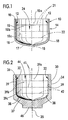
- an exemplary silica container is an untreated silica crucible 10.
- the crucible 10 generally has an inner surface 12, an outer surface 14, a centerline 15 and a top edge 16.
- the inner surface 12 defines an open cavity 24 into which polycrystalline silicon is loaded.
- the crucible 10 includes a bottom portion 17, a corner portion 18 and a side or wall portion 19, referred to hereinafter as the bottom 17, corner 18 and wall 19, respectively of the crucible 10.
- the wall 19 is substantially vertical and the bottom 17 is substantially horizontal.
- the wall 19 defines a substantially vertical circumferential area which includes a top portion 19a, a middle portion 19b and a bottom portion 19c, the top, middle and bottom portions 19a, 19b, 19c each including about 1/3 of the total surface area of the wall 19.
- the approximate divisions between the top, middle and bottom portions 19a, 19b and 19c are generally illustrated by phantom lines 21.
- the bottom 17 is parabolic, having a slope with a substantially greater horizontal component than vertical component.
- the corner 18 is a curved annular boundary region in the vicinity of the intersection of the wall 19 and bottom 17. The corner 18 intersects the wall 19 where the curvature of the corner 18 ceases, illustrated generally as line 22.
- the corner 18 has a radius of curvature which is less than the radius of curvature of the bottom 17 and generally intersects the bottom 17 where the radius of curvature changes.
- the corner 18 has upper and lower halves each of which include about half of the total surface area of the corner 18, with the upper half being closer to the wall 19 and the lower half being closer to the bottom 17.
- the centerline 15 of the crucible 10 is substantially parallel to the wall 19 and intersects a geometric centerpoint of the bottom 17.
- a graphite support vessel supports the silica container during formation of silicon melt therein and during production of single-crystal silicon from the molten silicon.
- the graphite support vessel can be an untreated or treated graphite support vessel.
- An untreated graphite support vessel consists essentially of carbon in its graphite form.
- a treated graphite support vessel comprises a core vessel which consists essentially of graphite and has inner and outer surfaces where at least a portion of the inner and/or the outer surface of the core vessel has been treated (e.g. coated) according to various methods presently known or later developed in the art. Such treatment methods presently include, for example, forming coatings of SiC, TiC, NbC, TaC, ZrC, BN or glasseous carbon on the surface or growing such coatings in situ at the surface of the core vessel.
- the support vessel will generally be cup-shaped and have inner and outer surfaces that define a structure which is adapted to receive a silica container such that the silica container is nested in the graphite support vessel with at least a portion of the inner surface of the support vessel being in contact with at least a portion of the outer surface of the container.
- the region of contact between the inner surface of the support vessel and the outer surface of the container defines an interface region.
- the support vessel is preferably further adapted for use in a Czochralski-type crystal puller.
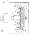
- an exemplary graphite support vessel is an untreated graphite susceptor 30.
- the susceptor 30 has an inner surface 32, an outer surface 34, a centerline 35 and a top edge 36.
- the inner surface 32 of the susceptor 30 defines an open cavity 44 and includes a bottom portion 37, a corner portion 38 and a side or wall portion 39, referred to hereinafter as the bottom 37, corner 38 and wall 39, respectively, of the susceptor 30.
- the susceptor bottom 37 is substantially horizontal and the susceptor wall 39 is substantially vertical. More specifically, the bottom 37 is approximately parabolic and has a slope with a substantially greater horizontal component than vertical component.
- the susceptor wall 39 defines a circumferential area, which includes a top portion 39a, a middle portion 39b and a bottom portion 39c, the top, middle and bottom portions 39a, 39b and 39c each including about 1/3 of the total surface area of the wall 39.
- the approximate divisions between the top, middle and bottom portions 39a, 39b and 39c are generally illustrated by phantom lines 41.
- the susceptor wall 39 is tapered open slightly relative to the true vertical, such that the diameter of the wall 39 at the top edge 36 of the susceptor 30 is slightly greater than the diameter of the wall 39 measured at point lower in the wall 39, for example, at the bottom portion 39b of the wall 39.
- the slightly open-tapered wall 39 facilitates receipt of a silica crucible 10 or other silica container into the open cavity 44.
- the susceptor corner 38 is a curved annular boundary region in the vicinity of the intersection of the wall 39 and bottom 37.
- the corner 38 intersects the wall 39 where the curvature of the corner 38 ceases, illustrated generally as line 42.
- the corner 38 has a radius of curvature which is less than the radius of curvature of the bottom 37 and generally intersects the bottom 37 where the radius of curvature changes.
- the corner 38 has upper and lower halves each of which include about half of the total surface area of the corner 38, with the upper half being closer to the wall 39 and the lower half being closer to the bottom 37.
- the centerline 35 of the susceptor 30 is substantially parallel to the wall 39 and intersects a geometric centerpoint of the bottom 37.
- the susceptor 30 further includes a base 46 located underneath the bottom portion 37 of the inner surface 32.
- the base 46 is adapted for connection to a movable pedestal 52 of a Czochralski-type crystal puller.
- FIG 3 shows crucible 10 situated in and supported by susceptor 30 in a Czochralksi-type crystal puller 50, with the base 46 of the susceptor 30 attached to a movable pedestal 52.
- This configuration is typical for producing single-crystal silicon using a batch Czochralski-type process.
- the portion of the inner surface 32 of the susceptor 30 defined by the bottom 37, corner 38 and bottom portion 39b of the wall 39 is in contact with the outer surface 14 of the corresponding portions 17, 18 and 19b of the crucible 10.
- the interface region for this container-support vessel system is defined by this area of contact between the crucible and the susceptor.
- the extent and specific location of the interface region will depend on the particular designs for the silica container and the graphite support vessel. Such designs are generally based on structural support and heat transfer considerations. Moreover, the area of contact defining the interface region will, for batch processes, vary with time during the crystal-growing process.
- the molten silicon 48 which is below the melt surface 58 exerts a hydrostatic (gravitational) force on the wall 19, corner 18 and bottom 17 of the crucible 10. Because the heated silica container is softened at the melt temperatures, the hydrostatic / gravitational forces operate to force the softened silica container against the graphite support vessel.
- the level of the molten silicon decreases as the silicon ingot forms, and therefore, the hydrostatic pressure exerted on the wall 19, corner 18 and bottom 17 decreases as the single crystal ingot is drawn, thereby allowing the upper portions 19a, 39a of the walls 19 39 to release from each other, and resulting in a decrease in the amount of contact between the outer surface 14 of crucible wall 19 and the inner surface 32 of the support vessel wall 39 as the crystal is pulled.
- subregions of the interface region based upon the time of contact between the walls of the silica container and the support vessel: (1) a no-contact region which is located substantially above the initial melt line (ie, above the initial level of the surface 58 of the molten silicon 48); (2) a temporary-contact region which is located substantially below the initial melt line but substantially above the final melt line; and (3) a continuous-contact region located substantially where the hydrostatic pressure and/or the weight of the silica container forces the softened container against the support vessel during the entire crystal-pulling process.
- the no-contact region correlates roughly with the top one-third of the interface region between the walls of the silica container and the graphite susceptor, illustrated therein as the top portions 19a and 39a, of the container and support vessel walls, respectively.
- the temporary-contact region generally correlates with the bottom two-thirds of the walls and the upper-half of the corner element.
- the temporary contact region may include the wall portions 19b, 19c, 39b, 39c and the upper halves of the corners 18, 38.
- the continuous contact region generally correlates with the bottoms 17, 37 and the lower halves of the corners 18, 38.
- the geometries of the crucible 10 and susceptor 30 illustrated in Figures 1, 2 and 3, respectfully, are exemplary.
- the geometries of the silica container and the graphite support vessel may vary substantially from the illustrated embodiments and still fall within the scope of the invention.
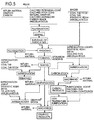
- One alternative design for the silica container and the graphite support vessel is shown in Figure 4.
- a double container system comprising an inner crucible 10' and an outer crucible 10'' situated in and supported by a graphite support vessel (susceptor 30') are configured in a manner which is typical for preparation of single-crystal silicon using a continuous Czochralski-type process.
- the cumulative concentration of alkali metals and/or alkaline-earth metals, particularly calcium, magnesium, strontium, lithium, sodium and potassium, which are present as impurities in bulk of the graphite support vessel and on its surface should generally be sufficiently low to prevent substantial non-uniform devitrification of the silica container at the interface region while the polycrystalline silicon is melted and the single-crystal silicon ingot is drawn from the molten silicon.
- the term "substantial non-uniform devitrification” is intended to mean localized crystallization of the vitreous silica which results in a commercially significant decrease in the structural integrity of the silica container (e.g. cusping, fluxing, pitting, bulging, bowing and/or other deformation) and/or a commercially significant decrease in the zero-dislocation length upon growth of a single-crystal silicon ingot from a silicon melt formed in the silica container.
- the decrease in zero-dislocation length is preferably less than about 10%, more preferably less than about 5%, even more preferably less than about 1% and most preferably less than about 0.5%.
- Substantial non-uniform devitrification is typically characterized by several observable features such as excessive formation of white powder, accompanied by significant pitting, cusping and/or fluxing. Fluxing relates to a localized softening of the silica container and is evidenced by a visually shiny or glossy appearance on the outer surface of the silica container. Fluxing is a particularly relevant indicator of detrimental non-uniform devitrification.
- the cumulative concentration of alkali metals and/or alkaline-earth metals present in the graphite support vessel is preferably low enough to avoid fluxing an area of greater than about 1 cm 2 . More preferably, the cumulative concentration is low enough such that less than about 0.5 cm 2 is fluxed.
- the concentration of the aforementioned impurities, particularly calcium, in an untreated graphite support vessel being used with an untreated silica container is preferably equal to or less than about 1.0 ppm relative to the weight of the graphite material of which graphite support vessel is composed. ( See , for example, Example 1).
- the concentration of the aforementioned impurities present in such a graphite support vessel is, in order of increasing preference, less than about 0.7 ppm by weight, less than about 0.5 ppm by weight, less than about 0.2 ppm by weight and most preferably less than about 0.1 ppm by weight.
- a higher concentration of alkali metal and alkaline-earth metal impurities, particularly Ca, can be tolerated without substantial non-uniform devitrification.
- the exact upper concentration limit of alkali and/or alkaline-earth metal impurities for avoiding substantial, non-uniform devitrification may vary depending on factors which include the cleanliness of the surfaces of the silica container and/or the graphite support vessel, the hot-zone temperature profile (temperature and time) being used for a particular crucible size and charge size, whether the silica container and/or graphite support vessel are treated, etc. Nonetheless, single crystal silicon of improved quality can be obtained according to the guidance and preferred concentration limits set forth above.
- the crucible can be placed in a conventional CZ silicon crystal growth apparatus and the polycrystalline silicon can be heated to melt the polycrystalline silicon until a pool of molten silica forms in the silica container.
- the heating profile is not narrowly critical, and will generally vary depending on the type of loading (ie, chunk, granular or mixed loadings), the size and design of the crucible, the size and type of crystal grower, etc.
- the pedestal 52 supporting the base 46 of the susceptor 30 is positioned such that the bottom 17 of the crucible 10 is near the top of the heater 54.
- the crucible 10 is gradually lowered into the space inside the heater 54.
- the speed at which the crucible 10 is lowered into closer proximity of the heater 54 and the value of other factors affecting melting of the polycrystalline silicon, such as heater power, crucible rotation and system pressure, are generally known in the art.
- the temperature of the region of contact between the crucible 10 and susceptor 30 at corners 18, 38 is at least about 1500 °C for an 18" (about 46 cm) diameter crucible charged with about 60 kg polycrystalline silicon during a meltdown period ranging of about 4 hours and, alternatively, at least about 1550 °C for an 18" (about 46 cm) diameter crucible charged with about 70 kg polycrystalline silicon during a meltdown period ranging from about 4 hours to about 6 hours.
- the temperature of the high heat-flux corner region is preferably at least about 1600 °C for a 22" (about 56 cm) diameter crucible charged with about 100 kg of polycrystalline silicon during a melt-down period ranging from about 7 hours to about 10 hours, or with a larger, 120 kg, charge and a melt-down period of about 10 hours.
- the corner temperature is preferably at least about 1650 °C, and can also be at least about 1675 °C or at least about 1700 °C.
- the meltdown period for such a 24"/140 kg system will vary with temperature, but can typically range from about 10 hours to about 12 hours at about 1650 °C and from about 8 hours to about 10 hours at temperatures ranging from about 1675 °C to about 1700 °C.
- a 32" (about 81 cm) diameter crucible charged with an amount of polycrystalline silicon ranging from about 160 kg to about 200 kg can be heated to a corner temperature of at least about 1650 °C, or more preferably, at least about 1675 °C or at least about 1700 °C. These higher temperatures are preferred to allow for a melt-down period for such a 32"/160-200 kg system which is commercially reasonable -- for example, ranging from about 12 hours to about 15 hours.
- silica container diameters, charge sizes and melt-down periods, and particularly, the combination of such parameters with the various temperatures are recited as being exemplary of the advantages of the present invention, and are not intended to be limiting as to the scope of the invention.
- a person skilled in the art will readily appreciate that the use of the aforedescribed low impurity support vessel allows, in general, for the silica container to be heated to higher temperatures without the detrimental effects on crystal growth which are associated with known systems. The capability of using higher temperatures translates into increased productivity through either larger charge sizes and/or reduced melt-down periods.
- the polycrystalline silicon is typically exposed, while heating, to a purge gas to flush out undesirable gasses such as SiO(g) and CO(g) originating from the reaction of SiO(g) with hot graphite.
- the purge gas is typically an inert gas such as argon and typically flows at a rate ranging from about 10 l/min to about 300 l/min, depending on the type and size of the crystal puller.
- a single-crystal silicon ingot is drawn from the molten silicon according to a Czochralski-type process.
- the single-crystal silicon ingot 55 is drawn in a Czochralski-type crystal puller 50 from a silicon melt formed in a silica crucible 10 supported by a graphite susceptor 30.
- the particular methods and conditions for drawing the single-crystal silicon ingot are known in the art.
- the high temperatures established during melt formation are generally maintained while the single-crystal silicon melt is drawn.
- the high purity graphite support vessels (e.g. susceptor 30) of the present invention are used to support a silica container (e.g.
- the temperature of the portion of the graphite support vessel subjected to the highest heat flux and having the highest temperatures can be maintained at or above about 1500 °C, or if necessary, at or above about 1525 °C, 1550 °C, 1575 °C, 1600 °C, 1625 °C, 1650 °C, 1675 °C or 1700 °C during production of the single-crystal silicon ingot therefrom (typically, for a period of at least about 4 hours or at least about 5 hours) without causing substantial non-uniform devitrification of the silica container in the interface region. While the temperature of the graphite support vessel (e.g.
- concentration and temperature values are to be considered exemplary and instructive only; in general, the most preferred concentration of alkali and alkaline-earth metals for any system or configuration is, as discussed above, a concentration sufficiently low to prevent substantial non-uniform devitrification of the silica container at the interface region while the polycrystalline silicon is melted and the single-crystal silicon ingot is drawn from the molten silicon.
- High purity graphite support vessels having alkaline-earth metal and alkali metal impurities, particularly calcium impurities, present at concentrations suitable for use in the present invention can be prepared in the same general manner in which such support vessels are currently made, with particular attention made to selection of filler and binder raw materials having a lower concentration of such impurities, and with special emphasis on purification steps, to ensure a satisfactorily low level of alkali and alkaline-earth metal impurities.
- a detailed description of the manufacturing process for producing graphite is set forth in T. Ishikawa & T. Nagaoki (English Editor I.C. Lewis) Recent Carbon Technology , especially pp. 22-58, JEC Press, 1983.
- a filler material e.g. calcinated petroleum coke
- a binder e.g. coal tar pitch
- the resulting mixture is formed into the desired shape (e.g. ingot), typically by a molding or extrusion process.
- the formed material is then baked in a carbonization process, and the resulting carbonized material is graphitized, either directly, or following steps during which it is impregnated and rebaked to increase its density and/or following high-temperature purification steps.
- Such purification steps include subjecting either baked carbon and/or graphitized carbon to halogen gasses at temperatures of about 2500 °C for extensive periods of time.
- Alkali and alkaline-earth metal impurities are removed during the graphitization steps, and/or through refining treatments in which impurities are removed using high-temperature purification processes.
- the stock graphite is then machined to form the graphite support vessel of the present invention.
- Commercial manufacturers of graphite support vessels e.g. UCAR, Clarksburg, WVa are capable of achieving the purity levels required for the graphite support vessels of the present invention.
- single-crystal silicon ingots were produced from silicon melts formed in untreated vitreous silica crucibles.
- the silica crucibles were supported by graphite susceptors having varying concentrations of calcium (ranging from about 0.1 ppm to about 1.8 ppm). The number of neck attempts to draw the silicon ingot was recorded.
- the quality of the vitreous quartz crucible used in each run was observed, with particular attention to the level of devitrification, pitting, cusping and fluxing of the crucible wall.
- the crucibles used with the susceptors having a high concentration of calcium were observed to have heavy devitrification, with a significant amount of pitting, cusping and fluxing of the crucible wall.
- silica crucibles used with the graphite susceptors having a low concentration of calcium were observed to have, at most, light devitrification, with a minimum amount of cusping, fluxing and pitting of the crucible wall.
- the data of Figure 6 indicates that for runs in which the silicon crystal was drawn with a low number of neck attempts, zero-dislocation growth was achieved in 100% of cases using the low-calcium-content susceptors, but in only 60% of the cases using the high-calcium-content susceptors.
- zero-dislocation growth was achieved in 72% of the cases using the low-calcium-content susceptors, but in only 40% of the cases using the high-calcium-content susceptors.
- the use of low-calcium-content susceptors clearly impacts the extent to which zero-dislocation growth of single-crystal silicon is achieved.
Landscapes
- Chemical & Material Sciences (AREA)
- Engineering & Computer Science (AREA)
- Materials Engineering (AREA)
- Organic Chemistry (AREA)
- Crystallography & Structural Chemistry (AREA)
- Metallurgy (AREA)
- Ceramic Engineering (AREA)
- Manufacturing & Machinery (AREA)
- Structural Engineering (AREA)
- Crystals, And After-Treatments Of Crystals (AREA)
Priority Applications (1)
| Application Number | Priority Date | Filing Date | Title |
|---|---|---|---|
| EP97304874A EP0892091A1 (fr) | 1997-07-03 | 1997-07-03 | Creuset de support en graphite présentant une faible concentration en impurités de calcium et sa mise en oeuvre dans la production de monocristaux de silicium |
Applications Claiming Priority (1)
| Application Number | Priority Date | Filing Date | Title |
|---|---|---|---|
| EP97304874A EP0892091A1 (fr) | 1997-07-03 | 1997-07-03 | Creuset de support en graphite présentant une faible concentration en impurités de calcium et sa mise en oeuvre dans la production de monocristaux de silicium |
Publications (1)
| Publication Number | Publication Date |
|---|---|
| EP0892091A1 true EP0892091A1 (fr) | 1999-01-20 |
Family
ID=8229396
Family Applications (1)
| Application Number | Title | Priority Date | Filing Date |
|---|---|---|---|
| EP97304874A Withdrawn EP0892091A1 (fr) | 1997-07-03 | 1997-07-03 | Creuset de support en graphite présentant une faible concentration en impurités de calcium et sa mise en oeuvre dans la production de monocristaux de silicium |
Country Status (1)
| Country | Link |
|---|---|
| EP (1) | EP0892091A1 (fr) |
Cited By (3)
| Publication number | Priority date | Publication date | Assignee | Title |
|---|---|---|---|---|
| EP0971054A1 (fr) * | 1998-07-09 | 2000-01-12 | Wacker Siltronic Gesellschaft für Halbleitermaterialien Aktiengesellschaft | Creuset-support pour supporter un creuset à fusion |
| CN101664955B (zh) * | 2009-09-26 | 2012-01-04 | 甘肃郝氏炭纤维有限公司 | 一种单晶炉用硬质复合石墨毡保温隔热桶制作工艺 |
| US10184193B2 (en) | 2015-05-18 | 2019-01-22 | Globalwafers Co., Ltd. | Epitaxy reactor and susceptor system for improved epitaxial wafer flatness |
Citations (6)
| Publication number | Priority date | Publication date | Assignee | Title |
|---|---|---|---|---|
| JPH0489388A (ja) * | 1990-07-27 | 1992-03-23 | Shin Etsu Handotai Co Ltd | チョクラルスキー法によるシリコン単結晶の製造方法 |
| DE4130253A1 (de) * | 1991-09-12 | 1993-03-18 | Ringsdorff Werke Gmbh | Mehrteiliger stuetztiegel |
| JPH0616495A (ja) * | 1992-06-26 | 1994-01-25 | Komatsu Denshi Kinzoku Kk | 高純度シリコン単結晶の製造方法および高純度シリコン単結晶 |
| EP0753605A1 (fr) * | 1995-06-14 | 1997-01-15 | MEMC Electronic Materials, Inc. | Procédé pour augmenter le rendement des monocristaux sans dislocations |
| US5616175A (en) * | 1994-07-22 | 1997-04-01 | Herecules Incorporated | 3-D carbon-carbon composites for crystal pulling furnace hardware |
| WO1998055238A1 (fr) * | 1997-06-03 | 1998-12-10 | Hitco Carbon Composites, Inc. | Composite pur utilise en tant que suscepteur |
-
1997
- 1997-07-03 EP EP97304874A patent/EP0892091A1/fr not_active Withdrawn
Patent Citations (6)
| Publication number | Priority date | Publication date | Assignee | Title |
|---|---|---|---|---|
| JPH0489388A (ja) * | 1990-07-27 | 1992-03-23 | Shin Etsu Handotai Co Ltd | チョクラルスキー法によるシリコン単結晶の製造方法 |
| DE4130253A1 (de) * | 1991-09-12 | 1993-03-18 | Ringsdorff Werke Gmbh | Mehrteiliger stuetztiegel |
| JPH0616495A (ja) * | 1992-06-26 | 1994-01-25 | Komatsu Denshi Kinzoku Kk | 高純度シリコン単結晶の製造方法および高純度シリコン単結晶 |
| US5616175A (en) * | 1994-07-22 | 1997-04-01 | Herecules Incorporated | 3-D carbon-carbon composites for crystal pulling furnace hardware |
| EP0753605A1 (fr) * | 1995-06-14 | 1997-01-15 | MEMC Electronic Materials, Inc. | Procédé pour augmenter le rendement des monocristaux sans dislocations |
| WO1998055238A1 (fr) * | 1997-06-03 | 1998-12-10 | Hitco Carbon Composites, Inc. | Composite pur utilise en tant que suscepteur |
Non-Patent Citations (2)
| Title |
|---|
| DATABASE WPI Section Ch Week 9219, Derwent World Patents Index; Class E36, AN 92-154461, XP002083896 * |
| PATENT ABSTRACTS OF JAPAN vol. 018, no. 222 (C - 1193) 21 April 1994 (1994-04-21) * |
Cited By (3)
| Publication number | Priority date | Publication date | Assignee | Title |
|---|---|---|---|---|
| EP0971054A1 (fr) * | 1998-07-09 | 2000-01-12 | Wacker Siltronic Gesellschaft für Halbleitermaterialien Aktiengesellschaft | Creuset-support pour supporter un creuset à fusion |
| CN101664955B (zh) * | 2009-09-26 | 2012-01-04 | 甘肃郝氏炭纤维有限公司 | 一种单晶炉用硬质复合石墨毡保温隔热桶制作工艺 |
| US10184193B2 (en) | 2015-05-18 | 2019-01-22 | Globalwafers Co., Ltd. | Epitaxy reactor and susceptor system for improved epitaxial wafer flatness |
Similar Documents
| Publication | Publication Date | Title |
|---|---|---|
| US5814148A (en) | Method for preparing molten silicon melt from polycrystalline silicon charge | |
| JP4225688B2 (ja) | ポリシリコン装填物からシリコンメルトを製造する方法 | |
| US5980629A (en) | Methods for improving zero dislocation yield of single crystals | |
| EP0756024A2 (fr) | Méthode pour la préparation de silicium fondu à partir d'une charge de silicium polycristallin | |
| JP4103593B2 (ja) | 固形状多結晶原料のリチャージ管及びそれを用いた単結晶の製造方法 | |
| EP2071059B1 (fr) | Creuset en verre de silice à pureté élevée utilisé pour produire un lingot en silicone monocristallin à large diamètre | |
| US5868835A (en) | Apparatus for recharging of silicon granules in a czochralski single crystal growing operation | |
| US20080289568A1 (en) | Quartz glass crucible, process for producing the same, and use | |
| EP0368586B1 (fr) | Appareillage pour la fabrication de monocristaux de silicium | |
| JPH01148782A (ja) | 単結晶引き上げ用石英ルツボ | |
| JP2004131317A (ja) | 石英ガラス部材の強化方法と強化処理した石英ガラスルツボ | |
| CN102272360A (zh) | 制备用于硅晶体生长的硅粉熔体的方法 | |
| US4936949A (en) | Czochraski process for growing crystals using double wall crucible | |
| EP0294758B1 (fr) | Appareillage pour la croissance de matériaux semi-conducteurs | |
| JP2601411B2 (ja) | 単結晶引上げ方法およびその装置 | |
| KR20230124725A (ko) | 단결정 실리콘 잉곳들의 성장 중의 버퍼 부재들의 사용 | |
| US5932002A (en) | Seed crystals for pulling a single crystal and methods using the same | |
| EP1905872A1 (fr) | Creuset en verre quartzeux d' excursion ascendante de simple cristal de silicium et procédé de fabrication du creuset en verre quartzeux | |
| JP2006124235A (ja) | 石英ガラスルツボとその製造方法および用途 | |
| JPH0692779A (ja) | 単結晶引き上げ用石英るつぼ | |
| WO2002055765A2 (fr) | Dispositif de tirage de cristal et procede de croissance d'un materiau semi-conducteur monocristallin | |
| JPH1129395A (ja) | 低濃度のカルシウム不純物を有するグラファイト支持容器および単結晶シリコンの製造におけるそれの使用 | |
| JPH01148783A (ja) | 単結晶引き上げ用石英ルツボ | |
| JPH09235186A (ja) | 単結晶引き上げ用種結晶及び該種結晶を用いた単結晶の引き上げ方法 | |
| JP7824935B2 (ja) | シリコン充填物を覆うためのカバー部材を有する結晶引上げシステム、及びシリコン溶融物をるつぼアセンブリ内で成長させるための方法 |
Legal Events
| Date | Code | Title | Description |
|---|---|---|---|
| PUAI | Public reference made under article 153(3) epc to a published international application that has entered the european phase |
Free format text: ORIGINAL CODE: 0009012 |
|
| AK | Designated contracting states |
Kind code of ref document: A1 Designated state(s): DE FR GB IT |
|
| AX | Request for extension of the european patent |
Free format text: AL;LT;LV;RO;SI |
|
| RIN1 | Information on inventor provided before grant (corrected) |
Inventor name: HANSEN, RICHARD LEE Inventor name: BANAN, MOHSEN |
|
| 17P | Request for examination filed |
Effective date: 19990522 |
|
| AKX | Designation fees paid |
Free format text: AT BE CH DE LI |
|
| RBV | Designated contracting states (corrected) |
Designated state(s): DE FR GB IT |
|
| 17Q | First examination report despatched |
Effective date: 20010821 |
|
| STAA | Information on the status of an ep patent application or granted ep patent |
Free format text: STATUS: THE APPLICATION IS DEEMED TO BE WITHDRAWN |
|
| 18D | Application deemed to be withdrawn |
Effective date: 20020301 |