EP0892137A2 - Stulpschienenbeschlag für eine Tür, ein Fenster oder dergleichen - Google Patents
Stulpschienenbeschlag für eine Tür, ein Fenster oder dergleichen Download PDFInfo
- Publication number
- EP0892137A2 EP0892137A2 EP98106676A EP98106676A EP0892137A2 EP 0892137 A2 EP0892137 A2 EP 0892137A2 EP 98106676 A EP98106676 A EP 98106676A EP 98106676 A EP98106676 A EP 98106676A EP 0892137 A2 EP0892137 A2 EP 0892137A2
- Authority
- EP
- European Patent Office
- Prior art keywords
- faceplate
- holding element
- support part
- fitting according
- projections
- Prior art date
- Legal status (The legal status is an assumption and is not a legal conclusion. Google has not performed a legal analysis and makes no representation as to the accuracy of the status listed.)
- Granted
Links
- 239000002184 metal Substances 0.000 description 2
- 229910052751 metal Inorganic materials 0.000 description 2
- 229920000642 polymer Polymers 0.000 description 2
- 238000004080 punching Methods 0.000 description 2
- 239000002023 wood Substances 0.000 description 2
- 229910001229 Pot metal Inorganic materials 0.000 description 1
- 229910000639 Spring steel Inorganic materials 0.000 description 1
- 238000005452 bending Methods 0.000 description 1
- 210000000078 claw Anatomy 0.000 description 1
- 210000005069 ears Anatomy 0.000 description 1
- 238000004049 embossing Methods 0.000 description 1
- 239000004744 fabric Substances 0.000 description 1
- 238000003780 insertion Methods 0.000 description 1
- 230000037431 insertion Effects 0.000 description 1
- 239000000463 material Substances 0.000 description 1
- 238000000465 moulding Methods 0.000 description 1
Images

Classifications
-
- E—FIXED CONSTRUCTIONS
- E05—LOCKS; KEYS; WINDOW OR DOOR FITTINGS; SAFES
- E05C—BOLTS OR FASTENING DEVICES FOR WINGS, SPECIALLY FOR DOORS OR WINDOWS
- E05C9/00—Arrangements of simultaneously actuated bolts or other securing devices at well-separated positions on the same wing
- E05C9/004—Faceplates ; Fixing the faceplates to the wing
-
- E—FIXED CONSTRUCTIONS
- E05—LOCKS; KEYS; WINDOW OR DOOR FITTINGS; SAFES
- E05C—BOLTS OR FASTENING DEVICES FOR WINGS, SPECIALLY FOR DOORS OR WINDOWS
- E05C9/00—Arrangements of simultaneously actuated bolts or other securing devices at well-separated positions on the same wing
- E05C9/22—Guides for sliding bars, rods or cables
Definitions
- This task is the beginning of the faceplate mentioned type in that the holding element at least one, in particular two laterally projecting Has projections, which on the side walls of the Attack the hardware groove and the retaining element in the Define the hardware groove.
- the holding element is advantageously U-shaped and the free ends are angled and facing each other. Through the free, angled and facing each other Ends of the holding element, which, for. B. the faceplate overlap, this is captive on the faceplate held.
- the visible surface of the faceplate can be advantageous in the area where they are overlapped by the free ends will be provided with depressions so that the Holding element, or the angled ends sunk in the Face plate can be stored.
- a further training provides that the faceplate with a support part for the fastening screw is provided and that between the faceplate and the support part Holding element is interposed.
- this Embodiment is e.g. B. the support part with the Face plate and the intermediate holding element riveted.
- the spring element can be disc-shaped be formed or it is still U-shaped trained and is open at the bottom.
- the support part is usually used when the faceplate is screwed into the frame with screws and to increase the burglar resistance should be avoided that the Screws bent when pressing on the wing.
- With the support part is the screw shaft in immediate Supported near the groove base of the fitting groove, so that the Screw essentially only shear stressed is, and thereby the screw much higher forces can record.
- This support part is now from the two Flanked legs of the holding element, so that the Face plate in the area where it is with the frame is screwed, is already pre-fixed to the frame.
- the edge is designed as a projection or the edge has protrusions. This edge then digs after inserting the faceplate into the fitting groove in whose side face.
- this is disc-shaped spring element between two spatial shapes snatchable what is achieved by that Spring element has a specific embossing.
- the spring element and the two are curved Side edges protrude from the faceplate. The This allows the faceplate to be easily inserted into the hardware groove be used. However, the spring element then deforms and snaps from the first to the second Jardinform and is now aligned parallel to the faceplate and there are two side edges of the spring element the faceplate. The width of the Spring element enlarged and the side edges dig into the side surfaces of the fitting groove and hold the Faceplate fixed.
- the faceplate is with a support part for the fastening screw provided, the support part as a holding element is trained.
- the support part has projections that attack on the side walls of the hardware groove.
- the Support part and the holding element are thus in one single component, d. H. united in the support part.
- the holding element 6 is also as Spring element 5 formed and between the faceplate 3rd and the support member 14 interposed and is riveted 15 captured.
- the spring element 5 has edges 11, which protrude laterally over the faceplate 3, in preferred embodiment, the faceplate 3 in the area of Edges 11, as shown in FIG. 1b, have recesses 12 having. If the faceplate 3 with this spring element 5th inserted in the fitting groove 2, then dig Edges 11 in the side surfaces 13 of the fitting groove 2 and hold the faceplate 3 in the fitting groove 2.
- FIG. 5 shows another embodiment of the Invention shown, also in this Embodiment, the holding element 6 as a spring element 5th is trained.
- the holding element 6 is essentially U-shaped bent, with this embodiment the free ends 9 over the entire length of the Holding element 6 extend and the legs 8 above the Projections 10 are bent outwards.
- this Embodiment does not have the faceplate 3 with Recesses 12 are provided.
- FIG. 6 shows a further embodiment of the Invention, in which between the faceplate 3 and Support part 14 also a disc-shaped holding element 6 is riveted.
- This holding element 6 is also as Spring element 5 is formed and has edges 11 which into the side surfaces 13 of the fitting groove 2, according to the embodiment according to FIG. 3.
- the cold element 6 is shaped in accordance with FIG. 6 or prepunched that there is a first and a second Can take spatial form.
- Figure 6 is the second Shown spatial shape, which then takes the holding element 6, when the faceplate 3 is inserted into the fitting groove 2 is.
- the side edges of the holding element 6 abut the undersides of the faceplate 3.
- the other spatial form is shown in Figure 6a, in which the holding element 6 a has a curved shape.
- This holding element 6 is essentially U-shaped formed and has angled free ends 9, which face each other.
- the legs 8 are with the Provide projections 10, which are on the side surfaces 13th the hardware groove 2 can deform.
- the free ends are 9 between the faceplate 3 and the support part 14 interposed and jammed there.
Landscapes
- Engineering & Computer Science (AREA)
- Mechanical Engineering (AREA)
- Window Of Vehicle (AREA)
- Wing Frames And Configurations (AREA)
- Special Wing (AREA)
- Connection Of Plates (AREA)
- Measuring Pulse, Heart Rate, Blood Pressure Or Blood Flow (AREA)
Abstract
Description
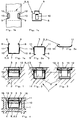
- Figur 1
- einen Schnitt durch einen Rahmen einer Tür, eines Fensters o.dgl. mit in eine Beschlagnut eingesetzter Stulpschiene mit Treibstange und an der Stulpschiene festgelegtem Halteelement gemäß einer ersten Ausführungsform;
- Figur 1a
- das Halteelement gemäß Figur 1 im Querschnitt;
- Figur 1b
- das Halteelement gemäß Figur 1 in der Draufsicht;
- Figur 1c
- das Halteelement gemäß Figur 1 in der Seitenansicht;
- Figuren 2, 3
- zwei weitere Ausführungsformen des erfindungsgemäßen Stulpschienenbeschlages, wobei die Stulpschiene mit einem Abstützteil versehen ist und das Halteelement zwischen der Stulpschiene und dem Abstützteil zwischengeschaltet ist;
- Figuren 2a, 3a
- Schnitte durch die Halteelemente gemäß der Figuren 2 und 3;
- Figur 4
- die Anordnung gemäß Figur 1 jedoch in einem aus Kunststoff bestehenden Rahmen eines Fensters, einer Tür o.dgl.;
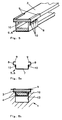
- Figur 5
- eine perspektivische Ansicht einer Stulpschiene mit Treibstange und die Stulpschiene übergreifendem Halteelement gemäß einem weiteren Ausführungsbeispiel;
- Figur 5a
- einen Querschnitt durch das Halteelement gemäß Figur 5;
- Figur 5b
- einen Querschnitt durch das die Stulpschiene mit Treibstange umgreifenden Halterelement, welches in dem Rahmen eingesetzt ist;
- Figur 6
- eine Anordnung gemäß Figur 3, wobei das Halteelement scheibenförmig ausgebildet ist
- Figur 6a
- einen Querschnitt durch das Halteelement gemäß Figur 6;
- Figur 7
- einen Querschnitt durch einen Rahmen einer Tür, eines Fensters o.dgl. mit in eine Beschlagnut eingesetzter Stulpschiene mit Treibstange und angenietetem Abstützteil, wobei das Abstützteil als Halteelement ausgebildet ist;
- Figur 7a
- einen Querschnitt durch das Halteelement gemäß Figur 7;
- Figur 8
- einen Querschnitt durch einen Rahmen einer Tür, eines Fensters o.dgl. mit in eine Beschlagnut eingesetzter Stulpschiene mit Treibstange und angenietetem Abstützteil, wobei das Abstützteil von einem aus Kunststoff bestehenden Halteelement umgriffen ist;
- Figur 8a
- einen Querschnitt durch das Halteelement gemäß Figur 8;
- Figur 9
- einen Querschnitt durch einen Rahmen einer Tür, eines Fensters o.dgl. mit in eine Beschlagnut eingesetzter Stulpschiene mit Treibstange und angenietetem Abstützteil, wobei das Abstützteil als Halteelement ausgebildet ist; und
- Figur 9a
- einen Querschnitt durch das Halteelement gemäß Figur 9.
Claims (12)
- Stulpschienenbeschlag mit einer in eine Beschlagnut (2) einer Tür, eines Fensters o.dgl. einlegbaren Stulpschiene (3), die ein- oder mehrteilig sein kann, und ggf. einen dazugehörigen Beschlag mit Treibstange (4), wobei die Breite der Beschlagnut (2) geringfügig größer ist als die Breite der Stulpschiene (3) und die Stulpschiene (3) mit einem diese in der Beschlagnut (2) fixierenden Halteelement (6) verbunden ist, dadurch gekennzeichnet, dass das Halteelement (6) wenigstens einen, insbesondere zwei seitlich auskragende Vorsprünge (10) aufweist, welche an den Seitenflächen (13) der Beschlagnut (2) angreifen und das Halteelement (6) in der Beschlagnut (2) festlegen.
- Stulpschienenbeschlag nach Anspruch 1, dadurch gekennzeichnet, dass das Halteelement (6) in die Stulpschiene (3), insbesondere in seitliche Ausnehmungen (12) eingehängt ist und die Stulpschiene (3) zumindest teilweise umgreift.
- Stulpschienenbeschlag nach einem der vorhergehenden Ansprüche, dadurch gekennzeichnet, dass das Halteelement (6) ein Federelement (5) ist.
- Stulpschienenbeschlag nach einem der vorhergehenden Ansprüche, dadurch gekennzeichnet, dass das Halteelement (6) U-förmig ausgebildet ist und die freien Enden (9) abgewinkelt und einander zugewandt sind.
- Stulpschienenbeschlag nach einem der vorhergehenden Ansprüche, dadurch gekennzeichnet, dass das Halteelement (6) U-förmig ausgebildet ist und die beiden Schenkel (8) die Vorsprünge (10) aufweisen, die voneinander weg auskragen.
- Stulpschienenbeschlag nach Anspruch 5, dadurch gekennzeichnet, dass die Vorsprünge (10) von ausgebogenen Stanzlappen gebildet werden.
- Stulpschienenbeschlag nach Anspruch 1, dadurch gekennzeichnet, dass die Stulpschiene (3) mit einem Abstützteil (14) für eine Stulpschienen-Befestigungsschraube versehen ist und dass zwischen der Stulpschiene (3) und dem Abstützteil (14) das Halteelement (6) zwischengeschaltet ist.
- Stulpschienenbeschlag nach einem der Ansprüche 3 bis 7, dadurch gekennzeichnet, dass das Federelement (5) scheibenförmig ausgebildet ist und der Rand (11) als Vorsprung (10) ausgebildet ist, bzw. die Vorsprünge (10) aufweist.
- Stulpschienenbeschlag nach Anspruch 8, dadurch gekennzeichnet, dass das an der Stulpschiene (3) anliegende scheibenförmige Federelement (5) in seiner ersten Raumform eine gewölbte Form aufweist, bei welcher die Ränder (11) von der Stulpschine (3) weg ragen und aus dieser ersten Raumform in eine zweite Raumform schnappbar ist, in welche die Ränder (11) zumindest teilweise an der Stulpschiene (3) anliegen.
- Stulpschienenbeschlag nach Anspruch 1, dadurch gekennzeichnet, dass die Stulpschiene (3) mit einem Abstützteil (14) für die Befestigungsschraube versehen ist und dass das Abstützteil (14) als Halteelement (6) ausgebildet ist.
- Stulpschienenbeschlag nach Anspruch 10, dadurch gekennzeichnet, dass das Abstützteil (14) mit Vorsprüngen (10) versehen ist, die an den Seitenwänden (13) der Beschlagnut (2) angreifen.
- Stulpschienenbeschlag nach Anspruch 1, dadurch gekennzeichnet, dass das Halteelement (6) als Kunststoffteil ausgebildet ist und ein an der Stulpschiene (3) befestigtes Abstützteil (14) von unten, d.h. von der der Stulpschiene (3) abgewandten Seite umgreift und mit seinen freien Enden (9) am Abstützteil (14) bzw. zwischen der Stulpschiene (3) und dem Abstützteil (14) festgelegt ist.
Applications Claiming Priority (2)
| Application Number | Priority Date | Filing Date | Title |
|---|---|---|---|
| DE29712614U DE29712614U1 (de) | 1997-07-17 | 1997-07-17 | Stulpschienenbeschlag |
| DE29712614U | 1997-07-17 |
Publications (3)
| Publication Number | Publication Date |
|---|---|
| EP0892137A2 true EP0892137A2 (de) | 1999-01-20 |
| EP0892137A3 EP0892137A3 (de) | 1999-06-30 |
| EP0892137B1 EP0892137B1 (de) | 2002-09-11 |
Family
ID=8043228
Family Applications (1)
| Application Number | Title | Priority Date | Filing Date |
|---|---|---|---|
| EP98106676A Expired - Lifetime EP0892137B1 (de) | 1997-07-17 | 1998-04-11 | Stulpschienenbeschlag für eine Tür, ein Fenster oder dergleichen |
Country Status (4)
| Country | Link |
|---|---|
| EP (1) | EP0892137B1 (de) |
| AT (1) | ATE223994T1 (de) |
| DE (2) | DE29712614U1 (de) |
| ES (1) | ES2179395T3 (de) |
Cited By (2)
| Publication number | Priority date | Publication date | Assignee | Title |
|---|---|---|---|---|
| EP1126110A1 (de) * | 2000-02-17 | 2001-08-22 | Molitor Patent GmbH | Schliessvorrichtung für Türen und Fenster |
| EP1260662A3 (de) * | 2001-05-22 | 2004-02-04 | Siegenia-Aubi Kg | Kupplungsvorrichtung für Treibstangen von Treibstangenbeschlägen |
Families Citing this family (8)
| Publication number | Priority date | Publication date | Assignee | Title |
|---|---|---|---|---|
| DE19820742A1 (de) * | 1998-05-08 | 1999-11-11 | Winkhaus Fa August | Beschlagteil eines an einem Rahmen anzubringenden Beschlagsystems, beispielsweise eines Fenster- oder Türbeschlags |
| DE19834042C2 (de) * | 1998-07-29 | 2002-01-24 | Siegenia Frank Kg | Treibstangenbeschlag mit einer Eckumlenkung |
| DE19913306A1 (de) * | 1999-03-24 | 2000-09-28 | Winkhaus Fa August | Beschlagsystem |
| DE19954723A1 (de) * | 1999-11-12 | 2001-06-07 | Roto Frank Ag | Beschlageinheit zur Montage an einem Fenster, einer Tür oder dergleichen sowie Verfahren zur Herstellung einer derartigen Beschlageinheit |
| DE10008733A1 (de) | 2000-02-24 | 2001-08-30 | Aubi Baubeschlaege Gmbh | Beschlag für ein Fenster oder eine Tür |
| BE1015892A6 (nl) * | 2004-02-05 | 2005-11-08 | Reynaers Aluminium Nv | Constructie voor een raam, deur of dergelijke. |
| DE202007006223U1 (de) * | 2007-04-27 | 2007-06-28 | Siegenia-Aubi Kg | Beschlag |
| DE102010062309A1 (de) * | 2010-12-01 | 2012-06-21 | Aug. Winkhaus Gmbh & Co. Kg | Befestigungseinrichtung einer Stulpschiene eines Treibstangenbeschlages |
Citations (6)
| Publication number | Priority date | Publication date | Assignee | Title |
|---|---|---|---|---|
| DE1559790A1 (de) | 1966-03-02 | 1970-02-19 | Weidtmann Wilhelm | In eine Ausnehmung einsetzbarer,zur Abdeckung von Stangenverschluessen dienender Fensterbeschlag |
| DE7108480U (de) | 1971-06-03 | Hahn F Gmbh | Vorrichtung zum Befestigen und Fuhren einer Schubstange eines Beschlages fur Fenster oder Türen | |
| DE2217458A1 (de) | 1971-04-15 | 1972-11-02 | Mühle, Manfred, 4972 Löhne | Halterung für Betätigungsschienen und ähnliche Beschläge an Fenstern, Türen oder dergleichen |
| FR2414606A1 (fr) | 1978-01-16 | 1979-08-10 | Massard Sa Ets Jean | Dispositif pour la fixation d'une tetiere de cremone ou autre dans une feuillure |
| EP0056484A2 (de) | 1981-01-17 | 1982-07-28 | SCHÜCO Heinz Schürmann GmbH & Co. | Mit einem Stulpschienenbeschlag ausgerüsteter Tür- oder Fensterflügel |
| EP0444405A2 (de) | 1990-02-26 | 1991-09-04 | August Bilstein GmbH & Co. KG | Beschlag für Fenster und Türen |
Family Cites Families (5)
| Publication number | Priority date | Publication date | Assignee | Title |
|---|---|---|---|---|
| BE744166A (nl) * | 1970-01-08 | 1970-06-15 | P V B A Vancraeynest Gebroeder | Grendel. |
| DE2407196C3 (de) * | 1974-02-15 | 1985-11-14 | August Bilstein GmbH & Co KG, 5828 Ennepetal | Treibstangenbeschlag für insbesondere aus Kunststoff oder Holz bestehende Fenster, Türen od.dgl. |
| DE8117338U1 (de) * | 1981-06-11 | 1981-08-20 | Wilh. Frank Gmbh, 7022 Leinfelden-Echterdingen | Vorrichtung zum befestigen einer stulpschiene und zur fuehrung einer treibstange eines ablaengbaren treibstangenbeschlags |
| DE29619198U1 (de) * | 1996-11-05 | 1996-12-19 | Gretsch-Unitas GmbH Baubeschläge, 71254 Ditzingen | Stulpschienenbeschlag |
| DE19646988C5 (de) * | 1996-11-14 | 2014-07-03 | Roto Frank Ag | Beschlag für ein Fenster |
-
1997
- 1997-07-17 DE DE29712614U patent/DE29712614U1/de not_active Expired - Lifetime
-
1998
- 1998-04-11 EP EP98106676A patent/EP0892137B1/de not_active Expired - Lifetime
- 1998-04-11 AT AT98106676T patent/ATE223994T1/de not_active IP Right Cessation
- 1998-04-11 DE DE59805485T patent/DE59805485D1/de not_active Expired - Fee Related
- 1998-04-11 ES ES98106676T patent/ES2179395T3/es not_active Expired - Lifetime
Patent Citations (6)
| Publication number | Priority date | Publication date | Assignee | Title |
|---|---|---|---|---|
| DE7108480U (de) | 1971-06-03 | Hahn F Gmbh | Vorrichtung zum Befestigen und Fuhren einer Schubstange eines Beschlages fur Fenster oder Türen | |
| DE1559790A1 (de) | 1966-03-02 | 1970-02-19 | Weidtmann Wilhelm | In eine Ausnehmung einsetzbarer,zur Abdeckung von Stangenverschluessen dienender Fensterbeschlag |
| DE2217458A1 (de) | 1971-04-15 | 1972-11-02 | Mühle, Manfred, 4972 Löhne | Halterung für Betätigungsschienen und ähnliche Beschläge an Fenstern, Türen oder dergleichen |
| FR2414606A1 (fr) | 1978-01-16 | 1979-08-10 | Massard Sa Ets Jean | Dispositif pour la fixation d'une tetiere de cremone ou autre dans une feuillure |
| EP0056484A2 (de) | 1981-01-17 | 1982-07-28 | SCHÜCO Heinz Schürmann GmbH & Co. | Mit einem Stulpschienenbeschlag ausgerüsteter Tür- oder Fensterflügel |
| EP0444405A2 (de) | 1990-02-26 | 1991-09-04 | August Bilstein GmbH & Co. KG | Beschlag für Fenster und Türen |
Cited By (2)
| Publication number | Priority date | Publication date | Assignee | Title |
|---|---|---|---|---|
| EP1126110A1 (de) * | 2000-02-17 | 2001-08-22 | Molitor Patent GmbH | Schliessvorrichtung für Türen und Fenster |
| EP1260662A3 (de) * | 2001-05-22 | 2004-02-04 | Siegenia-Aubi Kg | Kupplungsvorrichtung für Treibstangen von Treibstangenbeschlägen |
Also Published As
| Publication number | Publication date |
|---|---|
| EP0892137A3 (de) | 1999-06-30 |
| ES2179395T3 (es) | 2003-01-16 |
| DE59805485D1 (de) | 2002-10-17 |
| DE29712614U1 (de) | 1998-03-19 |
| EP0892137B1 (de) | 2002-09-11 |
| ATE223994T1 (de) | 2002-09-15 |
Similar Documents
| Publication | Publication Date | Title |
|---|---|---|
| EP1383967B1 (de) | Abdeckung für eine entwässerungseinrichtung | |
| AT402838B (de) | Dichtungsvorrichtung, insbesondere für türflügel | |
| DE4309088A1 (de) | Ortsfest einbaubare Scheibe für Kraftfahrzeuge | |
| DE3912135C3 (de) | Holz/Metall-Fenster | |
| EP0892137B1 (de) | Stulpschienenbeschlag für eine Tür, ein Fenster oder dergleichen | |
| DE102020105920A1 (de) | Verfahren zur Montage eines Rollladenkastens, Rollladenkasten und Statikteil | |
| EP1743992A2 (de) | Zaunbefestigung mit Zaunpfosten und Halterung | |
| CH663983A5 (de) | Treibstangenbeschlag fuer fenster oder tueren. | |
| DE4108547C1 (de) | ||
| DE60033988T2 (de) | Schliessblech | |
| DE19808847C2 (de) | Tür- oder Fensterbeschlag | |
| DE19740603C2 (de) | Stulpschienenbefestigung | |
| DE102007053340A1 (de) | Eckumlenkung für ein Treibstangenbeschlagsystem für einen Fenster- oder Türflügel | |
| EP1208281A1 (de) | Verriegelungsbeschlag | |
| EP2754803A2 (de) | Riegelstangenbeschlag für ein Fenster oder eine Tür | |
| EP3369946B1 (de) | Flachdübel und verfahren zum anbringen eines flachdübels in einer mauer | |
| DE4443232C1 (de) | Befestigungseinrichtung | |
| EP2132391B1 (de) | Treibstangenanordnung mit mindestens einer treibstange und mindestens einem treibstangenführungselement | |
| EP0964118B1 (de) | Schliessblechanordnung | |
| DE19834042C2 (de) | Treibstangenbeschlag mit einer Eckumlenkung | |
| DE102007051058B4 (de) | Befestigungsklammer und System zum Erstellen von Aufbauten | |
| DE102015216808A1 (de) | Beschlagsystem sowie Fenster, Tür oder dergleichen mit dem Beschlagsystem | |
| DE29507058U1 (de) | Rahmenprofil für feuerhemmende Fenster oder Türen | |
| DE10354310A1 (de) | Dichtung insbesondere selbsttätig absenkende Bodendichtung für Türen | |
| DE60300577T2 (de) | Riegelbeschlag für Schiebeflügel |
Legal Events
| Date | Code | Title | Description |
|---|---|---|---|
| PUAI | Public reference made under article 153(3) epc to a published international application that has entered the european phase |
Free format text: ORIGINAL CODE: 0009012 |
|
| AK | Designated contracting states |
Kind code of ref document: A2 Designated state(s): AT BE CH DE ES FR IT LI NL |
|
| AX | Request for extension of the european patent |
Free format text: AL;LT;LV;MK;RO;SI |
|
| PUAL | Search report despatched |
Free format text: ORIGINAL CODE: 0009013 |
|
| AK | Designated contracting states |
Kind code of ref document: A3 Designated state(s): AT BE CH CY DE DK ES FI FR GB GR IE IT LI LU MC NL PT SE |
|
| AX | Request for extension of the european patent |
Free format text: AL;LT;LV;MK;RO;SI |
|
| 17P | Request for examination filed |
Effective date: 19990630 |
|
| AKX | Designation fees paid |
Free format text: AT BE CH DE ES FR IT LI NL |
|
| 17Q | First examination report despatched |
Effective date: 20010712 |
|
| GRAG | Despatch of communication of intention to grant |
Free format text: ORIGINAL CODE: EPIDOS AGRA |
|
| GRAG | Despatch of communication of intention to grant |
Free format text: ORIGINAL CODE: EPIDOS AGRA |
|
| GRAH | Despatch of communication of intention to grant a patent |
Free format text: ORIGINAL CODE: EPIDOS IGRA |
|
| GRAH | Despatch of communication of intention to grant a patent |
Free format text: ORIGINAL CODE: EPIDOS IGRA |
|
| GRAA | (expected) grant |
Free format text: ORIGINAL CODE: 0009210 |
|
| AK | Designated contracting states |
Kind code of ref document: B1 Designated state(s): AT BE CH DE ES FR IT LI NL |
|
| REF | Corresponds to: |
Ref document number: 223994 Country of ref document: AT Date of ref document: 20020915 Kind code of ref document: T |
|
| REG | Reference to a national code |
Ref country code: CH Ref legal event code: EP |
|
| REG | Reference to a national code |
Ref country code: CH Ref legal event code: NV Representative=s name: TROESCH SCHEIDEGGER WERNER AG |
|
| REF | Corresponds to: |
Ref document number: 59805485 Country of ref document: DE Date of ref document: 20021017 |
|
| REG | Reference to a national code |
Ref country code: ES Ref legal event code: FG2A Ref document number: 2179395 Country of ref document: ES Kind code of ref document: T3 |
|
| ET | Fr: translation filed | ||
| PLBI | Opposition filed |
Free format text: ORIGINAL CODE: 0009260 |
|
| PLAX | Notice of opposition and request to file observation + time limit sent |
Free format text: ORIGINAL CODE: EPIDOSNOBS2 |
|
| PLBP | Opposition withdrawn |
Free format text: ORIGINAL CODE: 0009264 |
|
| 26 | Opposition filed |
Opponent name: SIEGENIA-AUBI KG Effective date: 20030604 |
|
| PLBD | Termination of opposition procedure: decision despatched |
Free format text: ORIGINAL CODE: EPIDOSNOPC1 |
|
| NLR1 | Nl: opposition has been filed with the epo |
Opponent name: SIEGENIA-AUBI KG |
|
| PLBB | Reply of patent proprietor to notice(s) of opposition received |
Free format text: ORIGINAL CODE: EPIDOSNOBS3 |
|
| PLBM | Termination of opposition procedure: date of legal effect published |
Free format text: ORIGINAL CODE: 0009276 |
|
| STAA | Information on the status of an ep patent application or granted ep patent |
Free format text: STATUS: OPPOSITION PROCEDURE CLOSED |
|
| 27C | Opposition proceedings terminated |
Effective date: 20030926 |
|
| NLR2 | Nl: decision of opposition |
Effective date: 20030926 |
|
| PGFP | Annual fee paid to national office [announced via postgrant information from national office to epo] |
Ref country code: NL Payment date: 20050412 Year of fee payment: 8 Ref country code: FR Payment date: 20050412 Year of fee payment: 8 Ref country code: CH Payment date: 20050412 Year of fee payment: 8 |
|
| PGFP | Annual fee paid to national office [announced via postgrant information from national office to epo] |
Ref country code: ES Payment date: 20050418 Year of fee payment: 8 |
|
| PGFP | Annual fee paid to national office [announced via postgrant information from national office to epo] |
Ref country code: BE Payment date: 20050509 Year of fee payment: 8 |
|
| PG25 | Lapsed in a contracting state [announced via postgrant information from national office to epo] |
Ref country code: ES Free format text: LAPSE BECAUSE OF NON-PAYMENT OF DUE FEES Effective date: 20060412 |
|
| PG25 | Lapsed in a contracting state [announced via postgrant information from national office to epo] |
Ref country code: LI Free format text: LAPSE BECAUSE OF NON-PAYMENT OF DUE FEES Effective date: 20060430 Ref country code: CH Free format text: LAPSE BECAUSE OF NON-PAYMENT OF DUE FEES Effective date: 20060430 Ref country code: BE Free format text: LAPSE BECAUSE OF NON-PAYMENT OF DUE FEES Effective date: 20060430 |
|
| PGFP | Annual fee paid to national office [announced via postgrant information from national office to epo] |
Ref country code: IT Payment date: 20060430 Year of fee payment: 9 |
|
| PG25 | Lapsed in a contracting state [announced via postgrant information from national office to epo] |
Ref country code: NL Free format text: LAPSE BECAUSE OF NON-PAYMENT OF DUE FEES Effective date: 20061101 |
|
| REG | Reference to a national code |
Ref country code: CH Ref legal event code: PL |
|
| NLV4 | Nl: lapsed or anulled due to non-payment of the annual fee |
Effective date: 20061101 |
|
| REG | Reference to a national code |
Ref country code: FR Ref legal event code: ST Effective date: 20061230 |
|
| REG | Reference to a national code |
Ref country code: ES Ref legal event code: FD2A Effective date: 20060412 |
|
| BERE | Be: lapsed |
Owner name: *GRETSCH-UNITAS G.M.B.H. BAUBESCHLAGE Effective date: 20060430 |
|
| PG25 | Lapsed in a contracting state [announced via postgrant information from national office to epo] |
Ref country code: FR Free format text: LAPSE BECAUSE OF NON-PAYMENT OF DUE FEES Effective date: 20060502 |
|
| PGFP | Annual fee paid to national office [announced via postgrant information from national office to epo] |
Ref country code: DE Payment date: 20080418 Year of fee payment: 11 |
|
| PGFP | Annual fee paid to national office [announced via postgrant information from national office to epo] |
Ref country code: AT Payment date: 20080415 Year of fee payment: 11 |
|
| PG25 | Lapsed in a contracting state [announced via postgrant information from national office to epo] |
Ref country code: IT Free format text: LAPSE BECAUSE OF NON-PAYMENT OF DUE FEES Effective date: 20070411 |
|
| PG25 | Lapsed in a contracting state [announced via postgrant information from national office to epo] |
Ref country code: DE Free format text: LAPSE BECAUSE OF NON-PAYMENT OF DUE FEES Effective date: 20091103 Ref country code: AT Free format text: LAPSE BECAUSE OF NON-PAYMENT OF DUE FEES Effective date: 20090411 |