EP0892146A2 - Bandes profilées en caoutchuc ou brosses - Google Patents
Bandes profilées en caoutchuc ou brosses Download PDFInfo
- Publication number
- EP0892146A2 EP0892146A2 EP98113028A EP98113028A EP0892146A2 EP 0892146 A2 EP0892146 A2 EP 0892146A2 EP 98113028 A EP98113028 A EP 98113028A EP 98113028 A EP98113028 A EP 98113028A EP 0892146 A2 EP0892146 A2 EP 0892146A2
- Authority
- EP
- European Patent Office
- Prior art keywords
- profile
- damping
- damping profile
- abutment
- roller shutter
- Prior art date
- Legal status (The legal status is an assumption and is not a legal conclusion. Google has not performed a legal analysis and makes no representation as to the accuracy of the status listed.)
- Withdrawn
Links
Images


Classifications
-
- E—FIXED CONSTRUCTIONS
- E06—DOORS, WINDOWS, SHUTTERS, OR ROLLER BLINDS IN GENERAL; LADDERS
- E06B—FIXED OR MOVABLE CLOSURES FOR OPENINGS IN BUILDINGS, VEHICLES, FENCES OR LIKE ENCLOSURES IN GENERAL, e.g. DOORS, WINDOWS, BLINDS, GATES
- E06B9/00—Screening or protective devices for wall or similar openings, with or without operating or securing mechanisms; Closures of similar construction
- E06B9/56—Operating, guiding or securing devices or arrangements for roll-type closures; Spring drums; Tape drums; Counterweighting arrangements therefor
- E06B9/58—Guiding devices
- E06B9/582—Means to increase gliss, light, sound or thermal insulation
Definitions
- the present invention relates to attenuation profiles such as e.g. a brush or rubber profile strip that in roller shutter guide profiles are used, as well as a roller shutter guide profile and a tool for inserting the damping profiles into Roller shutter guide profiles.
- attenuation profiles such as e.g. a brush or rubber profile strip that in roller shutter guide profiles are used, as well as a roller shutter guide profile and a tool for inserting the damping profiles into Roller shutter guide profiles.
- Roller shutter guide profiles made of plastic have a U-shaped Guide groove for roller shutters.
- the front of the roller shutter is adjacent to the bottom of the groove, while the two Leg of the U-shaped profile the front and the roller shutters Reach around on the rear, thus guiding the roller shutter.
- the legs of the U-shaped profile are again provided with T-shaped grooves in which immediately after the manufacture of the profile brush or rubber damping strips be used.
- the damping strips show a carrier in the form of a flat, e.g. fiber-reinforced Plastic strip on the middle and vertically the bristles or the rubber sealing lip is applied.
- the carrier is inserted into the T-shaped groove so that the Bristles protrude through the free opening of the T-slot.
- the roller shutter guide profile is generally provided in offered two price levels, namely once in an inexpensive Level without the damping profile and in a more expensive Price range with the damping profile.
- the cheaper leadership profiles do not wear the brush or rubber strips, but probably have the T-shaped grooves for this that are just empty.
- This task is characterized by a damping profile with the characteristics of claim 1 solved.
- the beam is lateral in the area of at least one edge Incisions and in particular recesses, can Damping profile simply in the designated T-shaped Be clipped in the groove of a roller shutter guide profile.
- the tabs formed between the incisions are for this sufficiently flexible.
- the orientation of the damping profile is irrelevant if the recesses are provided on both edges.
- a good Transverse stiffness results if there are two recesses in each Cross section of the carrier arranged opposite one another are.
- insertion or clipping is encouraged if the recesses of one edge are transverse of the carrier offset from the recesses on the other edge are.
- the width of the Carrier varies in the longitudinal direction. Are easy to make Recesses that are rectangular, triangular or trapezoidal in shape are.
- An advantageous device for retrofitting a is the damping profile on a roller shutter guide profile characterized in that a press jaw and an abutment are provided, which together in a substantially U-shaped Guide channel of a roller shutter guide profile insertable are, wherein lever means are provided for the abutment to be supported on a flank of the guide channel and the Press jaw on the opposite flank of the guide channel to press.
- the Device can in the longitudinal direction of the roller shutter guide profile be pulled over the damping profile when the abutment and / or the press jaw as a roller, in particular as a ball bearing are executed. So the entire damping profile is in one Work step clipped in like a zipper.
- the device has an abutment and has a press jaw as webs or ribs.
- the lever means a lever rod or a lever plate include the abutment at a free end carries, at a short distance from the abutment laterally the press jaw carries and one at a second free end Has grip section, then the required effort be specifically introduced via the press jaw. The The damping profile is then clipped in sections.
- the lever means a Form pliers with two long levers and two short levers
- the two long levers carry handle sections and their use two short levers to support the abutment and the press jaw, being between the long levers and the short levers Bearing provided and arranged so that the abutment and the press jaw are removed from each other when the Handle sections are pressed together.
- the gear ratio can be the required Force to be adjusted.
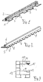
- Figure 1 is a damping profile with a stripe Carrier 1 and arranged in the middle, perpendicular to the carrier Brushes 2 shown.
- the carrier 1 is usually made of a fabric-reinforced strip or tape of about 6 mm Width and 0.4 mm thickness.
- the brushes 2 are in the Tissue of the carrier 1 anchored and stand as individual fibers perpendicularly from the carrier.
- the carrier 1 is regular Clearances laterally provided with rectangular recesses 3, their distance from each other approximately the width of the recesses 3 corresponds to 3 fixed between the recesses Areas 4 of approximately the same length as the recesses 3 form.
- the recesses 3 extend to a small distance to the area in which the brushes 2 in the carrier 1 are anchored.
- Figure 2 shows a damping profile also according to the invention made of rubber with a horizontal, strip-shaped Carrier 5, which is centered on a flat side and perpendicular to this carries a rubber rib 6.
- the carrier 5 is triangular Provide recesses 7, the trapezoidal between them Limit tabs 8 of the carrier 5.
- the carrier 5 and the Rubber rib 6 are in the dimensions of the commercially available Roller shutter guide profiles and in particular their T-shaped grooves customized. In particular, they can have the dimensions which were mentioned in connection with Figure 1.
- FIG. 3 is a roller shutter guide profile in a cross section shown perpendicular to the course of the grooves.
- the Roller shutter guide profile has a substantially U-shaped Groove 10 for the end guidance of the shutters.
- the groove 10 is of two groove flanks 11 with a depth of about 20 mm and one Groove base 12 limited to about 15 mm wide.
- Such roller shutter guide profiles are often cheaper when building a house Variant used in which the grooves 13 are not used stay. If no corresponding damping profile in the grooves 13 is provided, however, this leads to the fact that frequently used, very light aluminum and plastic roller shutters rattle in the guide groove 10 when there is wind pressure.
- the damping profiles according to FIG. 1 and FIG. 1 provide a remedy 2, whose position in the T-shaped groove 13 of Figure 3 with the reference number 15 is indicated.
- Figure 4 shows a tool in the form of a one-armed Lever with a base plate 20, one provided at the end Abutment 21 and one opposite the abutment 21 and from this spaced pressing jaw 22. That the abutment 21 opposite, free end of the lever 20 forms one Handle section 23.
- This tool can be retrofitted Insert the damping profile strips according to Figure 1 and Figure 2 are used so that the abutment 21 to the Groove base 12 is inserted into the groove 10 and the rib 22nd then lies over the open area of the T-shaped groove 13. An obliquely inserted damping profile strip can then pressed into the groove 13 via the lever action by means of the rib 22 become.
- the abutment 21 is supported on the from the groove base 12 adjacent side of the flank 11 and enables a large contact pressure via the lever ratio.
- FIG. 5 shows a pair of pliers 25, the two handle levers 26 and two working levers 27.
- the two parts the pliers are connected to each other via a bearing 28.
- a working lever 27 carries an abutment 29, while the opposite Working lever has a rib 30.
- the pliers geometry is chosen so that a compression of the Handle lever 26 inevitably pushing the working lever apart 27 causes. If the pliers are in the U-shaped groove 10 is inserted, the abutment 29 lies on a flank 11 the groove 10, while the rib 30 opposite in the T-shaped Groove 13 engages and a damping profile to be used there snaps into place.
- the rib 30 has a recess 31 provided that the brushes 2 or the rubber rib 6 during protects the press-in process.
- FIG. 6 shows pliers 35 with grip sections 36 and Working levers 37 articulated to one another via a bearing 38 are.
- the working levers 37 carry two small roles in shape of ball bearings 39. Again, the geometry is chosen so that a compression of the levers 36 separate the lever 37 and thus the rollers 39 causes.
- the roles 39 can in the U-shaped groove 10 of the roller shutter guide profile so that they are introduced in the area of the opening the T-shaped grooves 13 lie. When pushing the Roll 39 then becomes a one-sided damping profile snapped into the groove.
- the roles make it possible that the tool 35 in the longitudinal direction (perpendicular to the drawing plane of Figure 3) through the T-shaped grooves is and the rollers 39 then in the groove 13 and on roll the profile 15. This way it becomes very easy Profile strips pressed into the groove along their entire length.
- the carrier strip is 1, 5 of the damping profile on its brush 2 or the rubber rib 6 side facing away with a pressure sensitive adhesive provided that the damping profile strip slips in the T-shaped groove 13 prevented. This slipping occurs with unsecured damping profile strips due to friction of the roller shutter on the damping profile strip occasionally on.
- FIG. 7 shows a further, simple tool for inserting the damping profile strip according to FIG. 1 and Figure 2. It includes a handle 40 and a single one end roller 41, the axial width of which is somewhat smaller, than the opening of the T-shaped grooves 13. With the roller 41 the damping profile strip to be mounted can be supported without pressed in on the opposite groove flank 11 become. Here, too, the roller 41 enables the Tool on the strip and thus a simple and quick insertion over the entire length.
- the pressure element can also be used for brush profile strips not as a roll but as a non-rotating disc be. A disc slides easily over the brushes, even if it doesn't roll.
Landscapes
- Engineering & Computer Science (AREA)
- Structural Engineering (AREA)
- Architecture (AREA)
- Civil Engineering (AREA)
- Operating, Guiding And Securing Of Roll- Type Closing Members (AREA)
- Registering, Tensioning, Guiding Webs, And Rollers Therefor (AREA)
Applications Claiming Priority (6)
| Application Number | Priority Date | Filing Date | Title |
|---|---|---|---|
| DE19730384 | 1997-07-16 | ||
| DE19730384 | 1997-07-16 | ||
| DE19734953A DE19734953A1 (de) | 1997-07-16 | 1997-08-13 | Bürsten- oder Gummiprofilstreifen |
| DE19734953 | 1997-08-13 | ||
| DE29717014U DE29717014U1 (de) | 1997-09-25 | 1997-09-25 | Rolladenführungsprofil |
| DE29717014U | 1997-09-25 |
Publications (2)
| Publication Number | Publication Date |
|---|---|
| EP0892146A2 true EP0892146A2 (fr) | 1999-01-20 |
| EP0892146A3 EP0892146A3 (fr) | 1999-09-15 |
Family
ID=27217541
Family Applications (1)
| Application Number | Title | Priority Date | Filing Date |
|---|---|---|---|
| EP98113028A Withdrawn EP0892146A3 (fr) | 1997-07-16 | 1998-07-14 | Bandes profilées en caoutchuc ou brosses |
Country Status (1)
| Country | Link |
|---|---|
| EP (1) | EP0892146A3 (fr) |
Family Cites Families (7)
| Publication number | Priority date | Publication date | Assignee | Title |
|---|---|---|---|---|
| DE7517405U (de) * | 1975-10-23 | Gebr Koemmerling Kunststoffwerke Gmbh | Rolladen-Laufschiene | |
| DE6918624U (de) * | 1969-05-07 | 1969-10-30 | Karl Flach | Rolladenschiene |
| US4578851A (en) * | 1982-07-13 | 1986-04-01 | Song In W | Tool |
| DE8400766U1 (de) * | 1984-01-10 | 1984-03-08 | Katrapat AG, 6340 Baar | Vorrichtung zum kontinuierlichen Einbringen eines Fußes eines länglichen elastischen Streifens in einen Aufnahmeraum |
| US4528736A (en) * | 1984-06-04 | 1985-07-16 | Schlegel Canada Inc. | Weatherstrip installation apparatus |
| US5103547A (en) * | 1991-03-01 | 1992-04-14 | Emco Specialties, Inc. | Apparatus and method for placing weather stripping in a channel |
| DE29717014U1 (de) * | 1997-09-25 | 1997-11-13 | Friedrich, Gerhard, 59872 Meschede | Rolladenführungsprofil |
-
1998
- 1998-07-14 EP EP98113028A patent/EP0892146A3/fr not_active Withdrawn
Also Published As
| Publication number | Publication date |
|---|---|
| EP0892146A3 (fr) | 1999-09-15 |
Similar Documents
| Publication | Publication Date | Title |
|---|---|---|
| DE69705662T2 (de) | Rollvorrichtung für Schiebetüren, Fenster oder ähnliches | |
| DE4309088A1 (de) | Ortsfest einbaubare Scheibe für Kraftfahrzeuge | |
| DE2755695C3 (de) | Wärmegedämmtes Verbundprofil für Fenster, Türen u.dgl. | |
| CH654508A5 (de) | Abstreifer sowie werkzeug zur montage dieses abstreifers. | |
| EP2754805B1 (fr) | Tringle de verrouillage pour une crémone | |
| EP0182227A2 (fr) | Parclose | |
| DE4445132C1 (de) | Führungseinrichtung | |
| EP0104340B1 (fr) | Agencement, en particulier pour une cloison de douche | |
| EP0296280A2 (fr) | Longeron pour cadres de fenêtre | |
| EP0421316A2 (fr) | Joint d'étanchéité et de remplissage verrouillable, en particulier pour fenêtre de véhicule automobile | |
| DE29718854U1 (de) | Profilrahmen, insbesondere U-Profilrahmen zur Halterung von Flächenelementen wie Glasscheiben, Kunststoffplatten o.dgl. | |
| EP2754803B1 (fr) | Crémone de fenêtre ou de porte et tringle pour une telle crémone | |
| EP0892146A2 (fr) | Bandes profilées en caoutchuc ou brosses | |
| EP1992779A2 (fr) | Barre de charge pour écran de fenêtre | |
| DE4321466C2 (de) | Zarge für ein Fenster | |
| DE19734953A1 (de) | Bürsten- oder Gummiprofilstreifen | |
| DE8222539U1 (de) | Fenster- oder tuerfluegel | |
| DE20007641U1 (de) | Haltevorrichtung für ein Flächenelement | |
| EP3244001B1 (fr) | Porte comprenant une piece de serrage commandee par ressort et son procede de montage | |
| DE2151144A1 (de) | Dichtleiste fuer Fahrzeugschiebefenster | |
| EP1223350A2 (fr) | Agraffe pour des éléments en forme de plaque | |
| DE9300659U1 (de) | Streifenbürste | |
| DE19804925A1 (de) | Haltevorrichtung für Füllelemente in einer Wandkonstruktion | |
| DE29502101U1 (de) | Verbindung von flächigen, miteinander fluchtenden Planteilen | |
| DE2334881B2 (de) | Verriegelungsvorrichtung fuer fluegel, insbesondere kippschwenkfluegel von fenstern, tueren o.dgl. mit treibstangen, die ueber eine eckumlenkung miteinander verbunden sind |
Legal Events
| Date | Code | Title | Description |
|---|---|---|---|
| PUAI | Public reference made under article 153(3) epc to a published international application that has entered the european phase |
Free format text: ORIGINAL CODE: 0009012 |
|
| AK | Designated contracting states |
Kind code of ref document: A2 Designated state(s): AT BE CH DE DK LI |
|
| AX | Request for extension of the european patent |
Free format text: AL;LT;LV;MK;RO;SI |
|
| PUAL | Search report despatched |
Free format text: ORIGINAL CODE: 0009013 |
|
| AK | Designated contracting states |
Kind code of ref document: A3 Designated state(s): AT BE CH CY DE DK ES FI FR GB GR IE IT LI LU MC NL PT SE |
|
| AX | Request for extension of the european patent |
Free format text: AL;LT;LV;MK;RO;SI |
|
| RIC1 | Information provided on ipc code assigned before grant |
Free format text: 6B 25B 27/00 A, 6E 06B 9/58 B |
|
| AKX | Designation fees paid | ||
| REG | Reference to a national code |
Ref country code: DE Ref legal event code: 8566 |
|
| RBV | Designated contracting states (corrected) |
Designated state(s): AT BE CH DE DK LI |
|
| STAA | Information on the status of an ep patent application or granted ep patent |
Free format text: STATUS: THE APPLICATION IS DEEMED TO BE WITHDRAWN |
|
| 18D | Application deemed to be withdrawn |
Effective date: 20000316 |