EP0892162B1 - Brennkraftmaschine mit doppelter Verdichtung und doppelter Ausdehnung - Google Patents
Brennkraftmaschine mit doppelter Verdichtung und doppelter Ausdehnung Download PDFInfo
- Publication number
- EP0892162B1 EP0892162B1 EP98119735A EP98119735A EP0892162B1 EP 0892162 B1 EP0892162 B1 EP 0892162B1 EP 98119735 A EP98119735 A EP 98119735A EP 98119735 A EP98119735 A EP 98119735A EP 0892162 B1 EP0892162 B1 EP 0892162B1
- Authority
- EP
- European Patent Office
- Prior art keywords
- valve
- scavenge
- internal combustion
- combustion engine
- exhaust valve
- Prior art date
- Legal status (The legal status is an assumption and is not a legal conclusion. Google has not performed a legal analysis and makes no representation as to the accuracy of the status listed.)
- Expired - Lifetime
Links
- 238000002485 combustion reaction Methods 0.000 title claims description 170
- 230000006835 compression Effects 0.000 title description 27
- 238000007906 compression Methods 0.000 title description 27
- 230000009977 dual effect Effects 0.000 title description 8
- 239000000446 fuel Substances 0.000 claims description 139
- 230000006698 induction Effects 0.000 claims description 103
- 238000007789 sealing Methods 0.000 claims description 65
- 230000000712 assembly Effects 0.000 claims description 31
- 238000000429 assembly Methods 0.000 claims description 31
- 239000012530 fluid Substances 0.000 claims description 23
- 230000007246 mechanism Effects 0.000 claims description 10
- 230000008878 coupling Effects 0.000 claims description 7
- 238000010168 coupling process Methods 0.000 claims description 7
- 238000005859 coupling reaction Methods 0.000 claims description 7
- 230000000903 blocking effect Effects 0.000 claims description 6
- 238000004891 communication Methods 0.000 claims description 6
- 238000002347 injection Methods 0.000 claims description 6
- 239000007924 injection Substances 0.000 claims description 6
- 230000004044 response Effects 0.000 claims description 6
- 239000007921 spray Substances 0.000 claims description 4
- 230000004323 axial length Effects 0.000 claims description 2
- 238000000034 method Methods 0.000 description 5
- 239000000203 mixture Substances 0.000 description 4
- 230000008569 process Effects 0.000 description 3
- 230000009471 action Effects 0.000 description 2
- 230000014759 maintenance of location Effects 0.000 description 2
- 230000000630 rising effect Effects 0.000 description 2
- 238000013459 approach Methods 0.000 description 1
- 230000009286 beneficial effect Effects 0.000 description 1
- 230000008859 change Effects 0.000 description 1
- 230000003247 decreasing effect Effects 0.000 description 1
- 238000010790 dilution Methods 0.000 description 1
- 239000012895 dilution Substances 0.000 description 1
- 238000010438 heat treatment Methods 0.000 description 1
- 230000003134 recirculating effect Effects 0.000 description 1
- 230000029058 respiratory gaseous exchange Effects 0.000 description 1
- 230000002000 scavenging effect Effects 0.000 description 1
- 238000000926 separation method Methods 0.000 description 1
Images




Classifications
-
- F—MECHANICAL ENGINEERING; LIGHTING; HEATING; WEAPONS; BLASTING
- F01—MACHINES OR ENGINES IN GENERAL; ENGINE PLANTS IN GENERAL; STEAM ENGINES
- F01L—CYCLICALLY OPERATING VALVES FOR MACHINES OR ENGINES
- F01L9/00—Valve-gear or valve arrangements actuated non-mechanically
- F01L9/10—Valve-gear or valve arrangements actuated non-mechanically by fluid means, e.g. hydraulic
- F01L9/11—Valve-gear or valve arrangements actuated non-mechanically by fluid means, e.g. hydraulic in which the action of a cam is being transmitted to a valve by a liquid column
-
- F—MECHANICAL ENGINEERING; LIGHTING; HEATING; WEAPONS; BLASTING
- F01—MACHINES OR ENGINES IN GENERAL; ENGINE PLANTS IN GENERAL; STEAM ENGINES
- F01L—CYCLICALLY OPERATING VALVES FOR MACHINES OR ENGINES
- F01L11/00—Valve arrangements in working piston or piston-rod
- F01L11/02—Valve arrangements in working piston or piston-rod in piston
-
- F—MECHANICAL ENGINEERING; LIGHTING; HEATING; WEAPONS; BLASTING
- F02—COMBUSTION ENGINES; HOT-GAS OR COMBUSTION-PRODUCT ENGINE PLANTS
- F02B—INTERNAL-COMBUSTION PISTON ENGINES; COMBUSTION ENGINES IN GENERAL
- F02B25/00—Engines characterised by using fresh charge for scavenging cylinders
- F02B25/02—Engines characterised by using fresh charge for scavenging cylinders using unidirectional scavenging
- F02B25/08—Engines with oppositely-moving reciprocating working pistons
-
- F—MECHANICAL ENGINEERING; LIGHTING; HEATING; WEAPONS; BLASTING
- F02—COMBUSTION ENGINES; HOT-GAS OR COMBUSTION-PRODUCT ENGINE PLANTS
- F02B—INTERNAL-COMBUSTION PISTON ENGINES; COMBUSTION ENGINES IN GENERAL
- F02B41/00—Engines characterised by special means for improving conversion of heat or pressure energy into mechanical power
-
- F—MECHANICAL ENGINEERING; LIGHTING; HEATING; WEAPONS; BLASTING
- F02—COMBUSTION ENGINES; HOT-GAS OR COMBUSTION-PRODUCT ENGINE PLANTS
- F02B—INTERNAL-COMBUSTION PISTON ENGINES; COMBUSTION ENGINES IN GENERAL
- F02B41/00—Engines characterised by special means for improving conversion of heat or pressure energy into mechanical power
- F02B41/02—Engines with prolonged expansion
-
- F—MECHANICAL ENGINEERING; LIGHTING; HEATING; WEAPONS; BLASTING
- F02—COMBUSTION ENGINES; HOT-GAS OR COMBUSTION-PRODUCT ENGINE PLANTS
- F02B—INTERNAL-COMBUSTION PISTON ENGINES; COMBUSTION ENGINES IN GENERAL
- F02B73/00—Combinations of two or more engines, not otherwise provided for
-
- F—MECHANICAL ENGINEERING; LIGHTING; HEATING; WEAPONS; BLASTING
- F02—COMBUSTION ENGINES; HOT-GAS OR COMBUSTION-PRODUCT ENGINE PLANTS
- F02B—INTERNAL-COMBUSTION PISTON ENGINES; COMBUSTION ENGINES IN GENERAL
- F02B75/00—Other engines
- F02B75/02—Engines characterised by their cycles, e.g. six-stroke
-
- F—MECHANICAL ENGINEERING; LIGHTING; HEATING; WEAPONS; BLASTING
- F02—COMBUSTION ENGINES; HOT-GAS OR COMBUSTION-PRODUCT ENGINE PLANTS
- F02B—INTERNAL-COMBUSTION PISTON ENGINES; COMBUSTION ENGINES IN GENERAL
- F02B75/00—Other engines
- F02B75/28—Engines with two or more pistons reciprocating within same cylinder or within essentially coaxial cylinders
-
- F—MECHANICAL ENGINEERING; LIGHTING; HEATING; WEAPONS; BLASTING
- F02—COMBUSTION ENGINES; HOT-GAS OR COMBUSTION-PRODUCT ENGINE PLANTS
- F02B—INTERNAL-COMBUSTION PISTON ENGINES; COMBUSTION ENGINES IN GENERAL
- F02B75/00—Other engines
- F02B75/28—Engines with two or more pistons reciprocating within same cylinder or within essentially coaxial cylinders
- F02B75/30—Engines with two or more pistons reciprocating within same cylinder or within essentially coaxial cylinders with one working piston sliding inside another
-
- F—MECHANICAL ENGINEERING; LIGHTING; HEATING; WEAPONS; BLASTING
- F02—COMBUSTION ENGINES; HOT-GAS OR COMBUSTION-PRODUCT ENGINE PLANTS
- F02F—CYLINDERS, PISTONS OR CASINGS, FOR COMBUSTION ENGINES; ARRANGEMENTS OF SEALINGS IN COMBUSTION ENGINES
- F02F1/00—Cylinders; Cylinder heads
- F02F1/18—Other cylinders
- F02F1/183—Oval or square cylinders
-
- F—MECHANICAL ENGINEERING; LIGHTING; HEATING; WEAPONS; BLASTING
- F02—COMBUSTION ENGINES; HOT-GAS OR COMBUSTION-PRODUCT ENGINE PLANTS
- F02M—SUPPLYING COMBUSTION ENGINES IN GENERAL WITH COMBUSTIBLE MIXTURES OR CONSTITUENTS THEREOF
- F02M57/00—Fuel-injectors combined or associated with other devices
-
- F—MECHANICAL ENGINEERING; LIGHTING; HEATING; WEAPONS; BLASTING
- F02—COMBUSTION ENGINES; HOT-GAS OR COMBUSTION-PRODUCT ENGINE PLANTS
- F02M—SUPPLYING COMBUSTION ENGINES IN GENERAL WITH COMBUSTIBLE MIXTURES OR CONSTITUENTS THEREOF
- F02M61/00—Fuel-injectors not provided for in groups F02M39/00 - F02M57/00 or F02M67/00
- F02M61/14—Arrangements of injectors with respect to engines; Mounting of injectors
-
- F—MECHANICAL ENGINEERING; LIGHTING; HEATING; WEAPONS; BLASTING
- F02—COMBUSTION ENGINES; HOT-GAS OR COMBUSTION-PRODUCT ENGINE PLANTS
- F02B—INTERNAL-COMBUSTION PISTON ENGINES; COMBUSTION ENGINES IN GENERAL
- F02B53/00—Internal-combustion aspects of rotary-piston or oscillating-piston engines
- F02B2053/005—Wankel engines
-
- F—MECHANICAL ENGINEERING; LIGHTING; HEATING; WEAPONS; BLASTING
- F02—COMBUSTION ENGINES; HOT-GAS OR COMBUSTION-PRODUCT ENGINE PLANTS
- F02B—INTERNAL-COMBUSTION PISTON ENGINES; COMBUSTION ENGINES IN GENERAL
- F02B75/00—Other engines
- F02B75/02—Engines characterised by their cycles, e.g. six-stroke
- F02B2075/022—Engines characterised by their cycles, e.g. six-stroke having less than six strokes per cycle
- F02B2075/025—Engines characterised by their cycles, e.g. six-stroke having less than six strokes per cycle two
-
- F—MECHANICAL ENGINEERING; LIGHTING; HEATING; WEAPONS; BLASTING
- F02—COMBUSTION ENGINES; HOT-GAS OR COMBUSTION-PRODUCT ENGINE PLANTS
- F02B—INTERNAL-COMBUSTION PISTON ENGINES; COMBUSTION ENGINES IN GENERAL
- F02B3/00—Engines characterised by air compression and subsequent fuel addition
- F02B3/06—Engines characterised by air compression and subsequent fuel addition with compression ignition
-
- Y—GENERAL TAGGING OF NEW TECHNOLOGICAL DEVELOPMENTS; GENERAL TAGGING OF CROSS-SECTIONAL TECHNOLOGIES SPANNING OVER SEVERAL SECTIONS OF THE IPC; TECHNICAL SUBJECTS COVERED BY FORMER USPC CROSS-REFERENCE ART COLLECTIONS [XRACs] AND DIGESTS
- Y02—TECHNOLOGIES OR APPLICATIONS FOR MITIGATION OR ADAPTATION AGAINST CLIMATE CHANGE
- Y02T—CLIMATE CHANGE MITIGATION TECHNOLOGIES RELATED TO TRANSPORTATION
- Y02T10/00—Road transport of goods or passengers
- Y02T10/10—Internal combustion engine [ICE] based vehicles
- Y02T10/12—Improving ICE efficiencies
Definitions
- This invention relates generally to a compact internal combustion engine having dual compression and dual expansion and more particularly to an engine having multi-piston subassemblies preferably in back-to-back dynamically balanced units.
- An internal combustion engine generally includes one or more reciprocating pistons operably connected to a crankshaft by a connecting rod to deliver energy therefrom.
- Such engines can operate on a 4-stroke cycle with sequentially timed phases of intake, compression, power, and exhaust, as well as 2-stroke-cycle.
- a spark ignited engine a mixture of fuel and air is compressed by the piston within the closed confines of the cylinder. Near the end of the compression phase ignition occurs either by compression heating or by an ignition device to form hot burning gas which expands and drives the piston to create power.
- the power of engines having similar combustion systems can be compared on the basis of their relative air flows.
- the second is typified by the Wankel rotary piston engine in which a major geometric change achieves large "cylinders" in a small engine volume. The highest power density levels are achieved by combining these methods.
- the rotary piston engine is unsuited geometrically to withstand high cylinder pressures and to use high compression ratios so the fuel economy is poor and the potential for using turbo chargers to boost the inlet air to high density is limited to levels below conventional engines.
- an improved internal combustion engine which is (a) compact because it has large “cylinders” for induction relative to its volume, (b) efficient because it can use high compression ratios with a compact combustion space and, (c) low on NO x emissions because it achieves high levels of exhaust retention without loss of power.
- a housing defining an operating chamber and having an induction passage and a scavenge passage; a multi-piston subassembly including a first piston assembly reciprocally mounted in the operating chamber, the first piston assembly including a body a defining a first and second coaxial aligned bore, a second and third piston assembly reciprocally disposed in an opposed relationship in the first and second bores and defining with the body a combustion space therebetween, a first and second crankshaft respectively connected directly to the second and third piston assemblies for delivering power external therefrom in response to combustion in the combustion space.
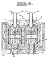
- an internal combustion engine 8 includes a housing 10 having a first or upper housing portion 12 and a second or lower housing portion 14 removably secured together by a plurality of fasteners or bolts 16.
- the upper housing portion 12 defines a pair of downwardly open, generally oblong first cavities 18 and the lower portion 14 defines a pair of upwardly open generally oblong second cavities 20.
- the first and second cavities 18 and 20 are arranged in an opposed and aligned relationship to form a pair of identical transversely oriented and longitudinally spaced operating chambers 22.
- each of the first cavities 18 is defined by a pair of generally parallel side surfaces 24 and 26, a pair of generally semicylindrical end surfaces 28 and 30 that blendingly connect together the side surfaces, and a ceiling surface 32.
- the first cavities 18 have a preselected width "W" in the longitudinal direction, a length "L” in the transverse direction, and a height “H” as indicated in the drawings.
- each of the second cavities 20 is defined by a pair of generally semicylindrical end surfaces 44 and 46 that blendingly connect together the side surfaces, and a bottom surface 48.
- the second cavities 20 have the same width "W” and the same height “H” as the first cavities 18, but the length "L1" of each second cavity 20 is greater than the length "L" of each first cavity 18.
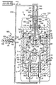
- each of the operating chambers 22 contains a multi-piston subassembly 50 including a first left longitudinal crankshaft 52 as shown at the left when viewing Figs. 2 and 3, a second right longitudinal crankshaft 54, a first or relatively large, low pressure piston assembly 56, and a pair of opposed smaller second and third high pressure piston assemblies 58 and 60.
- the first crankshaft 52 includes a plurality of longitudinally aligned spaced main bearing journals 62 having a central axis 66, and a pair of intermittent diametrically opposite cylindrical crankpins 68.
- the crankpins 68 are radially offset from the axis 66 of the main bearing journals 62.
- Each of the main bearing journals 62 of the first crankshaft 52 is rotatably supported between the upper and lower housing portions 12 and 14 of the housing 10, in a conventional manner, with a split sleeve bearing assembly 70.
- the longitudinally orientated central axis 66 is disposed generally at a right angle to the side surfaces 24, 26, 40, and 42 of the cavities 18 and 20.
- a first rear timing and balancing gear 74 is connected to a rear power take-off end 76 of the first crankshaft 52 external of the housing 10
- the first gear 74 is formed with a balance weight 78 on its side face positioned approximately 180 degrees away from the adjacent crankpin 68.
- a second front timing and balancing gear 80 is connected to an opposite front end 81 of the first crankshaft 52 external of the housing 10.
- the second gear 80 is formed with a balance weight 82 on its side face positioned approximately 180 degrees away from the adjacent crankpin 68.
- the second crankshaft 54 includes a plurality of spaced, longitudinally aligned main bearing journals 84 having a central axis 88, and a pair of intermittent, diametrically opposite cylindrical crankpins 90.
- the crank pins 90 are axially offset with respect to the main bearing journals 84 in a conventional manner.
- Each of the bearing journals 84 of the second crankshaft 54 is rotatably supported between the first and second housing portions 12 and 14 of the housing 10, in a conventional manner, with a split sleeve bearing assembly 92.
- the axes 66 and 88 of the first and second crankshafts 52 and 54 are generally parallel.
- a third rear timing and balancing gear 96 is connected to a rear end 97 of the second crankshaft 54 external of the housing 10 and in mesh with the first rear timing gear 74.
- the gear 96 is formed with a balance weight 98 on its side face positioned approximately 180 degrees away from the adjacent crankpin 90.
- a fourth front timing and balancing gear 100 is connected to an opposite front end 101 of the second crankshaft 54 external of the housing 10 and in mesh with the second front timing gear 80.
- the fourth gear 100 is formed with a balance weight 102 on its side face positioned approximately 180 degrees away from the adjacent crankpin 90.
- the rear first and third gears 74 and 96 mesh with one another and the front second and fourth gears 80 and 100 mesh with one another to impart phased counter rotation of the first and second crankshafts 52 and 54.
- the balance weights 78, 82, 98, and 102 together with the counter rotation of the first and second crankshafts 52 and 54 achieves complete balance with respect to forces and couples in the longitudinal, transverse, and perpendicular directions.
- a rear cover 104 is removably secured to the rear of the housing 10 to enclose the first and third gears 74 and 96 and a front cover 106 is removably secured to the front of the housing to enclose the second and fourth gears 80 and 100.
- the first piston assembly 56 is of generally oblong shape and is reciprocally and sealably disposed in the operating chamber 22 of the housing 10.
- the first piston assembly 56 includes a body 110 having a pair of generally parallel side surfaces 112 and 114, a first or left end portion 116, and a second or right end portion 118.
- the left end portion 116 includes a first semicylindrical end surface 120 and a second, semicylindrical end surface 122.
- the second semicylindrical end surface 122 extends outwardly beyond the first semicylindrical end surface 120 to form a generally horizontal flange portion 126.
- the right end portion 118 also includes a first semicylindrical end surface 130 and a second semicylindrical end surface 132 with the second semicylindrical end surface 132 extending outwardly beyond the first semicylindrical end surface 130 to form a generally horizontal flange portion 134.
- the body 110 of the first piston assembly 56 further includes a top working surface 140 and a bottom working surface 142.
- the working surfaces 140 and 142 are preferably parallel to each other and perpendicular to the side surfaces 112 and 114.
- the disposition of the top working surface 140 within the first cavity 18 defines an intake chamber 144 of variable volume.
- the disposition of the bottom working surface 142 within the second cavity 20 defines an exhaust chamber 146 of variable volume. In this specific instance the area of the bottom working surface 142 is greater than the area of the top working surface 140.
- the first piston assembly 56 is reciprocally moveable in the operating chamber 22 in a downward first direction, when viewing Fig. 2, increasing the volume of the intake chamber 144 and reducing the volume of the exhaust chamber 146 and in an upward second direction decreasing the volume in the intake chamber and increasing the volume in the exhaust chamber.
- a band 148 extends fully around the periphery of the side surfaces 112 and 114 and the semicylindrical end surfaces 120 and 130 of the body 110 adjacent the top working surface 140.
- the band 148 defines a pair of ring grooves 150 that extend fully around the periphery thereof.
- a pair of sealing rings 152 are received in the ring grooves 150 and sealingly engage with the surfaces 24, 26, 28, and 30 of the first cavity 18.
- a band 154 extends fully around the periphery of the side surfaces 112 and the semicircular side surfaces 122 and 132 of the body 110 adjacent the bottom working surface 142.
- the band 154 defines a pair of ring grooves 156 that extend fully around the periphery thereof.
- a pair of sealing rings 158 are disposed in the ring grooves 156 and sealingly engage with the surfaces 40, 42, 44, and 46 of the second cavity 20.
- first and second profiled crankshaft clearance passages 160 and 162 are defined in the body 110 of the first piston assembly 56 adjacent the left end portion 116 and the right end portion 118 respectively.
- the first passage 160 is arranged generally perpendicular to the side surfaces 112 and 114 and coaxial aligned with the main bearing journals 62 of the first crankshaft 52.
- the second passage 162 is arranged generally perpendicular to the side surfaces 112 and 114 and coaxially aligned with the main bearing journals 84 of the second crankshaft 54.
- Each of the first and second passages 160 and 162 is spaced approximately midway between the top and bottom working surfaces 140 and 142 and parallel thereto.
- each of the passages 160 and 162 Defined in the side surfaces 112 and 114 of the piston body 110 about each of the passages 160 and 162 are a pair of vertically orientated, oblong stepped clearance recesses 164 and 166.
- the first crankshaft 52 is operatively disposed in the passage 160 and the recesses 164 and 166 without making contact therewith.
- the second crankshaft 54 is operatively disposed in the passage 162 and the recesses 164 and 166 without making contact therewith.
- a first cylindrical piston bore 178 having an end surface 180 and a central axis 182 is defined in the body 110 of the first piston assembly 56.
- the first piston bore 178 extends inward from the semicylindrical end surface 120 of the first end portion 116.
- the central axis 182 is preferably located on a first plane that is parallel to and midway between the side surfaces 112 and 114, and on a second plane that is parallel to and midway between the top and bottom working surfaces 140 and 142.
- the central axis 182 of the piston bore 178 intersects the main bearing journal axis 66 of the first crankshaft 52 at a right angle.
- a second cylindrical piston bore 186 having an end surface 188 is defined in the body 110 of the first piston assembly 56.
- the second piston bore 186 having a central axis 190, extends inward from the first semicylindrical end surface 130 of the second end portion 118.
- the axes 182 and 190 of the piston bores 178 and 186 are coaxial.
- the central axis 190 of the second cylindrical piston bore 186 intersects the main bearing journal axis 88 of the second crankshaft 54 at a right angle.
- the second piston assembly 58 is sealingly engaged in the first cylindrical piston bore 178 and pivotally connected directly to the crankpin 68 of the first crankshaft 52.
- the third piston assembly 60 is sealingly engaged in the second cylindrical piston bore 186 and pivotally connected directly to the crankpin 90 of the second crankshaft 54 and in opposed relationship with the second piston assembly 58.
- the second and third piston assemblies 58 and 60 are identical and includes a body portion 198, a bearing cap 200, a pair of semicylindrical bearing shells 202 and 204 and a pair of fasteners or bolts 206 to removably secure the cap to the body portion 198.
- the body portion 198 includes a generally cylindrical head end 208 having a working surface 210 facing the respective end surfaces 180 and 188 of the bores 178 and 186 and a coupling end 212.
- the head end 208 as best shown in Fig. 2, defines a pair of sealing ring grooves 216 which are adapted to receive a pair of sealing rings 218 in the usual manner.
- the coupling end 212 defines a semicylindrical surface 220 for mounting the bearing shell 202 and the bearing cap 200 defines a semicylindrical surface 222 for mounting the bearing shell 204.
- Means 224 for pivotally connecting the respective second and third piston assemblies 58 and 60 directly to the crankpins 68 and 90 of the first and second crankshafts 52 and 54 includes the coupling end 212, the bearing cap 200, the bearing shells 202 and 204, and the bolts 206.
- a centrally located combustion space or chamber 254 is defined in the body 110 of first piston assembly 56 between the opposed working surfaces 210 of the second and third piston assemblies 58 and 60.
- the combustion space 254 being of variable volume, is defined by a horizontal top surface 256, a horizontal bottom surface 258, a pair of concave side surfaces 260 and 262 of the piston body 110, and the opposed working surfaces 212 of the piston assemblies 58 and 60.
- the engine 10 further includes flow control means 266 as illustrated in Figs 1, 2, 5 and 6 for selectively communicating the induction passage passages 282 and 286 with the intake chamber 144, the intake chamber 144 with the combustion space 254, the combustion space 254 with the exhaust chamber 146, and the exhaust chamber 146 with the scavenge passages 414 and 422.
- the flow control means 266 include induction means 268, intake means 270, exhaust means 272, and scavenge means 274.
- the upper portion 12 of the housing 10 further includes a left induction air manifold 280 defining a left air induction passage 282 and a right induction air manifold 284 defining a right air induction passage 286.
- the ceiling surface 32 of the first portion 12 of the housing 10 defined a plurality of induction ports 288. In this specific instance there are eight induction ports 288, four of which connects the left induction passage 282 with the intake chamber 144 and four of which that connects the right induction passage 286 with the intake chamber.
- An annular induction valve seating surface 290 is defined about each one of the induction ports 288.
- the induction means 268 operatively communicates the induction passages 282 and 286 with the intake chamber 144 via the induction passages 282 and 286 and the induction ports 288.
- the induction means 268 include a self opening induction poppet valve assembly 294 operatively disposed in each one of the induction port 288.
- Each one of the induction valve assemblies 294 includes an induction valve 296 and an induction valve spring 298.
- the induction valve 296 includes an induction valve stem 300, an induction head portion 302 disposed at one end of the induction valve stem and an enlarged end portion 303 disposed at an opposite end of the induction valve stem.
- the induction valve head portion 302 defines an annular induction valve sealing face 304 being of a dimension sufficient for sealingly seating of the induction valve 296 on the induction valve seating surface 290.
- the induction valve spring 298 urges the induction valve 296 against the induction valve seating surface 290 until the induction valve head portion 302 is moved from the induction valve seating surface.
- the induction valve spring 298 is located between the enlarged end 303 of the induction valve 296 and an induction valve guide web 305 in each of the induction ports 288 and is operative to urge the induction valve 296 against the respective induction valve seating surface 290.
- the piston body 110 defines a pair of first and second profiled intake ports 306 and 308 that are longitudinally aligned between the side surfaces 112 and 114 of the body.
- the intake ports 306 and 308 extends between the top working surface 140 and the top surface 256 of the combustion space 254 and have a central axes 310 and 312 respectively.
- the central axes 310 and 312 are generally perpending surface 140 and approximately midway )between the semicircular end surfaces 120 and 130 of the body 110.
- an annular seating surface 314 is defined in the top surface 256 of the combustion space 254 about each one of the intake ports 306 and 308.
- the intake means 270 operatively communicates the intake chamber 144 with the combustion space 254 via the first and second ports 306 and 308.
- the intake means 270 in this specific instance, includes an intake poppet valve assembly 316 of the self opening type, operatively mounted in each one of the intake ports 306 and 308 of the piston body 110.
- the intake poppet valve assembly 316 includes an intake valve 320 and a spring 322.
- the intake valve 320 includes a intake valve stem 324 and an intake valve head portion 326 disposed at the end of the intake valve stem.
- the intake valve head portion 326 defines an annular intake valve sealing face 328 of a dimension sufficient for sealingly seating of the intake valve sealing face on the intake valve seating surface 314.
- the intake valve spring 322 urges the intake valve 320 against the intake valve seating surface 314 until the intake valve head portion 326 is moved from the intake valve seating surface.
- the intake valve spring 322 is located between an enlarged end 330 of the intake valve stem 342 and an intake valve guide web 332 in each of the intake ports 306 and 308 and is operative to urge the intake valve 320 against the respective intake valve seating surface 314.
- simple self opening poppet intake valve assemblies 316 are shown it is recognized that other intake valve arrangements are possible with actuation, for example, by mechanical, electrical, or other means.
- the piston body 110 further defines a pair of first and second profiled exhaust ports 344 and 346 having a central axis 348 and 350 respectively.
- the exhaust ports 344 and 346 are longitudinally aligned between the side wall 112 and 114 of the body 110 and extend between the bottom working surface 142 and the bottom surface 258 of the combustion space 254.
- the central axes 348 and 350 of the exhaust ports 344 and 346 are generally perpendicular to the bottom working surface 142 and approximately midway between the semicircular end surfaces 122 and 132 of the piston body 110.
- the central axis 348 of first exhaust port 344 is axially aligned with the central axis 310 of first intake port 306 and the central axis 350 of the second exhaust port 344 is axially aligned with the central axis 312 of second intake port 308.
- An annular exhaust valve seating surface 352 is defined in the bottom surface 258 of the combustion space 254 and about each one the exhaust ports 344 and 346.
- the exhaust means 272 selectively communicates the combustion space 254 with the exhaust chamber 146 via the first and second exhaust ports 344 and 346.
- the exhaust means 272 includes an exhaust valve operating mechanism 356.
- the exhaust valve operating mechanism 356 includes an exhaust valve 358 operatively mounted in each one of the exhaust ports 344 and 346 and an exhaust valve support means 360 for reciprocally supporting the exhaust valves 358 on the housing 10 for movement with the low pressure piston assembly 56.
- the exhaust valves 358 each include an exhaust valve stem 366 and an exhaust valve head portion 368 disposed at the end of the exhaust valve stem.
- the exhaust valve head portion 368 defines an annular exhaust valve sealing face 370 of a dimension sufficient for sealingly seating of the exhaust valve sealing face on the exhaust valve seating surface 352 of the piston body 110.
- the exhaust valve support means 360 includes an exhaust valve sleeve bearing or exhaust valve guide 376 mounted in an exhaust valve pump cylinder 378 defined in the bottom surface 48 of the lower portion 14 of the housing 10 and a cylindrical exhaust valve pump piston 380 mounted on an end of the exhaust valve 358 opposite the exhaust valve head portion 368.
- the exhaust valve guide 376 encompasses the exhaust valve stem 366 and the exhaust valve pump piston 380 is adapted for reciprocal sliding movement in the exhaust valve pump cylinder 378.
- An outer exhaust valve pump chamber 382 is defined in the exhaust valve pump cylinder 378 outwardly of the exhaust valve pump piston 380.
- An inner exhaust valve spring chamber 384 is defined in the exhaust valve pump cylinder 378 inwardly of the exhaust valve pump piston 380.
- An exhaust valve spring 386 is disposed about the exhaust valve stem 366 in the exhaust valve spring chamber 384 and extends between the exhaust valve guide 376 and the exhaust valve pump piston 380.
- the exhaust valve actuating spring 386 urges the exhaust valve sealing face 370 of the exhaust in the exhaust valve seating surface 352 until the exhaust valve head portion 368 is moved away from exhaust valve seating surface.
- the lower portion 14 of the housing 10 defines a pair of left profiled scavenge ports 410 that connect the exhaust chamber 146 with a first scavenge passage 414 in a left scavenge manifold 416.
- An annular first scavenge valve seating surface 418 is defined about each of the left scavenge ports 410.
- the lower portion 14 of the housing 10 further defines a pair of right scavenge ports 420 that connects the exhaust chamber 146 with a second scavenge passage 422 defined in a right scavenge manifold 424.
- An annular second scavenge valve surface 426 is defined about each of the right scavenge ports 420.
- the scavenge means 274 selectively and operatively communicates the exhaust chamber 146 with the left and right scavenge manifolds 416 and 424 via the two pair of scavenge ports 410 and 420 and the first and second scavenge passages 414 and 422.
- the scavenge means 274 includes a scavenge valve operating mechanism 428.
- the scavenge valve operating mechanism 428 includes a scavenge valve 430 associated with each one of the scavenge ports 410 and 420 and scavenge valve support means 432 for reciprocally supporting the scavenge valves on the housing 10.
- the scavenge valve 430 includes a scavenge valve stem 434 and a scavenge valve head portion 436 disposed at the end of the scavenge valve stem.
- the scavenge valve head portion 436 defines an annular scavenge valve sealing face 438 of a dimension sufficient for sealingly seating of the scavenge valve sealing face on the respective scavenge valve seating surfaces 418 and 426.
- the scavenge valve support means 432 includes a scavenge valve sleeve bearing or scavenge valve guide 444 mounted in a scavenge valve pump cylinder 446 defined in the housing 10 and a cylindrical scavenge valve pump piston 448 mounted on an end of the scavenge valve stem 434 opposite the scavenge valve head portion 436.
- the scavenge valve guide 444 encompasses the scavenge valve stem 434 and the scavenge valve pump piston 448 is adapted for reciprocal sliding movement in the scavenge valve pump cylinder 446.
- An scavenge valve pump chamber 450 is defined in the scavenge valve pump cylinder 446 outwardly of the scavenge valve pump piston 448.
- a scavenge valve spring chamber 452 is defined in the scavenge valve pump cylinder 446 inwardly of the scavenge valve pump piston 448.
- a scavenge valve coil spring 454 is disposed about the scavenge valve stem 434 in the scavenge valve spring chamber 452 and extends between the scavenge valve guide 444 and the scavenge valve pump piston 448.
- the scavenge valve spring 454 urges the scavenge valve seating face 438 of the scavenge valve 4espective scavenge seating surfaces 418 and 426 until the scavenge valve head portion 436 is moved away from the scavenge valve seating surface.
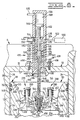
- the fuel introducing system 455 includes a fuel injector nozzle assembly 456 mounted on the first piston assembly 56 and communicates with the combustion space 254 and fuel injection means 458 including communication means 463 connected for movement with the first piston assembly 56 for controllably delivering fuel to the fuel injector nozzle assembly 456 in response to reciprocation of the first piston assembly 56.
- the communication means 463 includes a control member 464 and the fuel injector means 458 includes a fuel pump assembly 460.
- the fuel pump assembly 460 includes a pump body 462 in which the plunger or control member 464 is reciprocally positioned.
- the pump body 462 is removably secured by a pair of fasteners or bolts 466 in a mounting bore 468 defined in the upper portion 12 of the housing 10.
- the mounting bore 468 has a central axis 470 that is preferably located on a first plane that is parallel to and midway between the side surfaces 24 and 26 of the operating chamber 22 and on a second plane that is parallel to and midway between the semicylindrical end surfaces 28 and 44.
- the pump body 462 defines a fuel pump cylinder 474 having a central axis 475 that is coaxial with the axis 470 of the mounting bore 468.
- the control member 464 includes an outer rod portion 476 that extends through an outer rod bore 478 defined in the pump body 462, an intermediate fuel pump piston portion 480, and an inner rod portion 482 that extends through an inner rod bore 484 defined in the pump body.
- the cross-sectional areas of the outer and inner rod portions 476 and 482 within the fuel pump cylinder 474 are identical.
- the fuel pump piston portion 480 includes an outer control end surface 488, a cylindrical land surface 490 of a predetermined axial length, and a inner control end surface 492.
- An outer fuel pump chamber 494 is defined in the fuel pump cylinder 474 outwardly of the fuel pump piston portion 480 and an inner fuel pump chamber 498 is defined in the fuel pump cylinder inwardly of the fuel pump piston portion.
- the outer fuel pump chamber 494 is supplied fuel from a source 500 via a fuel line 502 and a transverse passage 504 defined in the pump body 462.
- a fuel transfer passage 506 is defined in the pump body 462 interconnecting the outer and inner fuel pump chambers 494 and 498.
- a first fuel pump port 510 defined in the pump body 462 connects the transfer passage 506 to the fuel pump cylinder 474.
- a passage blocking piston 514 of a solenoid actuated valve 516 is located in the transfer passage 506 between the outer fuel pump chamber 494 and the connection of the first fuel pump port 510 and is operative to selectively block fluid flow therethrough.
- a fill passage 518 is defined in the pump body 462 connecting the transverse passage 504 with the fuel pump cylinder 474.
- a second fuel pump port 522 defined in the pump body 462 connects the fuel pump cylinder 474 to the fill passage 518. The second port 522 is spaced axially inwardly of the first fuel pump port 510.
- a profiled nozzle bore 526, opening into the combustion space 254, is defined in the first piston assembly 56.
- the nozzle bore 526 has an axis co-axial with the central axis 470 of mounting bore 468.
- the injector nozzle assembly 456 is located in the nozzle bore 526 and operative to inject fuel into the combustion space 254.
- the nozzle assembly 456 includes a fuel injector body 530 defining a flow charge passage 532, an injector valve bore 534, and "spray orifice means 536.
- An injector valve spring 538 biases an injector valve 540 that is reciprocally disposed in the injector valve bore 534.
- the inner rod portion 482 of the control member 464 includes an enlarged end portion 544 threadably secured to the first piston assembly 56 to impart reciprocal movement of the fuel pump piston 480 in the fuel pump cylinder 474 with reciprocal movement of the first piston assembly 56.
- the end portion 544 includes a counterbore 546 that encompasses the injector body 530 of the injector nozzle assembly 456 capturing the injector nozzle assembly in the nozzle bore 526.
- the inner rod portion 482 further includes an axial supply passage 548 that connects the inner fuel pump chamber 498 of the fuel pump cylinder 474 to the flow charge passage 532 in the injector body 530.
- the exhaust means 272 further includes exhaust valve actuation means 560 for controllably displacing the exhaust valve sealing face 370 of each exhaust valve 358 away from its respective exhaust valve sealing surface 352 during a preselected range of movement of the first piston assembly 56 in the operating chamber 22.
- the exhaust valve actuation means 560 includes transfer means 562 for transferring hydraulic fluid between an exhaust valve transfer pump cylinder 564 defined in the pump body 462 and the exhaust valve pump chambers 382 associated with each of the exhaust valves 358.
- the transfer pump cylinder 564 has an axis that is coaxial with the axis 470 of the mounting bore 468 for the pump body 462.
- the outer rod portion 476 of the control member 464 extends into the exhaust valve transfer pump cylinder 564.
- a cylindrical transfer pump piston 566 is mounted on an end of the outer rod portion 476 for reciprocal movement therewith.
- a transfer pump chamber 568 is defined in the transfer pump cylinder 564 outwardly of the transfer pump piston 566.
- the cross-sectional area of the transfer pump chamber 568 is equal to the combined cross-section areas of the exhaust valve pump chambers 378 associated with each of the exhaust valves 358.
- a transfer conduit 570 interconnects the transfer pump chamber 568 with each of the exhaust valve pump chambers 382.
- the exhaust valve actuation means 560 further includes an exhaust valve actuator cylinder assembly 574.
- the exhaust valve actuator cylinder assembly 574 includes an exhaust valve actuator body 576 defining an exhaust valve actuator bore 578 with an exhaust valve actuator piston 580 slidably disposed in the exhaust valve actuator bore.
- An exhaust valve actuator fluid chamber 582 having a preselected volume is defined in the exhaust valve actuator bore 578 between the exhaust valve actuator piston 580 and one end of the exhaust valve actuator chamber.
- An exhaust valve actuator piston rod 584 is connected to the exhaust valve actuator piston 580 opposite the exhaust valve actuator chamber 582.
- An exhaust valve actuator cam follower 586 is connected at an end of the exhaust valve actuator rod 584 and rides on a exhaust valve cam 588 driven by the engine 8.
- the exhaust valve cam 588 makes one revolution for each revolution of the first and second crankshafts 52 and 54.
- An exhaust valve actuator spring 590 is disposed in the exhaust valve actuator chamber 582 between the exhaust valve actuator piston 580 and an end of the exhaust valve actuator chamber biases the exhaust valve cam follower 586 against the exhaust valve cam 588.
- the exhaust valve actuator chamber 582 is connected to the transfer conduit 570 by a branch conduit 592.
- the scavenge means 274 further includes scavenge valve actuation means 594 for controllably displacing the scavenge valve sealing face 438 of each scavenge valve 430 away from its respective scavenge valve seating surfaces 418 and 426 at a preselected time.
- the scavenge valve actuation means 594 includes a scavenge valve actuator assembly 596.
- the scavenge valve actuator assembly 596 includes a scavenge valve actuator body 598 defining a scavenge valve cylindrical actuator bore 600 with an scavenge valve actuator piston 602 slidably disposed in the scavenge valve actuator bore.
- a scavenge valve actuator fluid chamber 604 having a preselected volume is defined in the scavenge valve actuator bore 602 between the scavenge valve actuator piston 602 and one end of the scavenge valve actuator chamber.
- a scavenge valve actuator piston rod 606 is connected to the scavenge valve actuator piston 602 opposite the scavenge valve actuator chamber 604.
- a scavenge valve actuator cam follower 608 is connected to an end of the scavenge valve actuator piston rod 606 and rides on a scavenge valve cam 610 driven by the engine 8. The scavenge valve cam 610 makes one revolution for each revolution of the first and second crankshafts 52 and 54.
- a conduit 614 connects the scavenge valve actuator chamber 604 with each of the scavenge valve pump chambers 450 associated with each of the scavenge valves 430.
- the pair of opposed high pressure piston assemblies 58 and 60 of the dual compression and dual expansion internal combustion engine 8 are directly mounted on the respective pair of crankpins 68 and 90 of the geared together, counter rotating, crankshafts 52 and 54.
- the high pressure piston assemblies 58 and 60 are reciprocally and sealably disposed in their respective bores 178 and 186 of the low pressure piston assembly 56 and driven by combustion in the combustion space 254 transferring energy to the crankshafts 52 and 54.
- the orbital movement of the high pressure piston assemblies 58 and 60 and the pressure caused by the expanding exhaust gas in the exhaust chamber 146 acting on the bottom working surface 142 of the low pressure piston assembly 56 reciprocally drives the low pressure piston assembly in the operating chamber 22.
- crankshafts 52 and 54 can be added along the crankshafts 52 and 54 by adding additional crankpins 68 and 90, flow control means 226, and fuel introducing systems 455 in the manner of the additional cylinders of an in-line conventional engine.
- the multi-piston subassembly 50 may have only one crankshaft 52 and one high pressure piston assembly 58 directly mounted on the crankshaft 52 and disposed in one cylindrical piston assembly bore 178 defined in the body 110 of the low pressure piston assembly 56.
- other operating chambers 22, with alternative multi-piston subassemblies 50 can be added along the crankshaft 52 by adding additional crankpins 68, flow control means 226, and fuel introducing systems 455.
- the disposition of the top surface 140 of the low pressure piston assembly 56 within the first cavity 18 defines the intake chamber 144 of varying volume.
- the disposition of the second and third piston assemblies 58 and 60 within their respective bores 178 and 186 of the low pressure piston assembly 56 defines the variable volume combustion chamber 254.
- the disposition of the bottom working surface 142 of the low pressure piston assembly 56 in the second cavity 20 defines the variable volume exhaust chamber 146. Air, fuel, and gas of combustion move from the intake chamber 144 to the exhaust chamber 146 through the intake means 270 and the exhaust means 272 in the low pressure piston assembly 56, but in the process the air and fuel are compressed and combusted and gas is expanded in the combustion space 254 between the high pressure piston assemblies 56 and 60.
- step A begins at approximately -450 degrees of rotation of the crankshafts 52 and 54 and ends at approximately -270 degrees for a duration of approximately 180 degrees.
- the low pressure piston assembly 56 is moved in the first direction in the operating chamber 22, away from the ceiling 32 of the intake chamber 144 increasing the volume of the intake chamber and inducting a charge of air through the induction passages 282 and 286 of the left and right induction manifolds 280 and 284, and the self opening induction poppet valve assemblies 29 disposed in each of the induction ports 288. Movement of the low pressure piston assembly 56 in the intake chamber 144 lowers the pressure in the intake chamber below the pressure in the left and right induction passages 282 and 286.
- the higher pressure in the induction passages 282 and 286 acts on the induction valve head portions 302 within the intake chamber 144 overcoming the bias of the induction valve springs 298 moving the induction valve sealing faces 304 away from the induction valve seating surfaces 290.
- the intake valves 320 of the poppet intake valve assembly 316 disposed in the first and second intake ports 306 and 308 of the low pressure piston assembly 56 are maintained in the closed position by high pressure in the combustion chamber 254.
- the high pressure is created by sequential compression of air, combustion, and expansion of burning gas from steps D, E, and F of another one of the plurality of cycles occurring during the same time interval.
- the high pressure acts on the ends of the intake valve head portions 326 within the combustion chamber 254, forcing the intake valve sealing face 328 against the intake valve sealing surface 314.
- Step B begins at approximately -270 of crankshafts 52 and 54 rotation and ends at approximately -180 degrees for a duration of approximately 90 degrees.
- the low pressure piston assembly 56 is moved in the second direction towards the ceiling 32 of the intake chamber 144 compressing the charge of inducted air in the intake chamber.
- the induction valves 296 of the induction valve assemblies 294 are maintained sealingly seated against the induction valve seating surfaces 314 by the pressure created by the air being compressed within the intake chamber 144 acting on the ends of the induction valve head portions 302 within the intake chamber 144.
- the pressure within the combustion space 254 is greater than the pressure created by the compression of the air in the intake chamber 144 and the poppet intake valves 316 are maintained in the closed position.
- the pressure in the combustion chamber 254 is caused by the expansion of burning gas in the combustion chamber 254 from step G of the another one of the plurality of cycles occurring during the same time interval.
- the high pressure acts on the ends of the intake valve head portions 326 of the intake valves 320 within the combustion chamber 254 forcing the intake valve sealing face 328 against the intake valve sealing surface 314.
- Step C begins at approximately -180 degrees of rotation of the crankshafts 52 and 54 and ends at approximately -90 degrees for a duration of approximately 90 degrees.
- the low pressure piston assembly 56 is moved further in the second direction, continuing to compress the charge of induction air in the intake chamber 144 while transferring the charge of compressed air to the combustion space.
- the pressure of compression in the intake chamber 144 is greater than the pressure in the combustion chamber 254 and the bias of the intake valve springs 322 and the intake valves 320 are forced away from the intake valve seating surfaces 314 by the pressure of compression acting of the surfaces of the intake valve head portions 326 adjacent the intake valve stems 324.
- the second and third piston assemblies 58 and 60 are moved in their respective bores 178 and 186 compressing the charge of compressed air in the combustion space 254.
- the exhaust valves 358 are closed and the exhaust valve sealing faces 370 are maintained against their respective seating surfaces 352 by the bias of the exhaust valve springs 386 and the rising pressure of compression in the combustion space 254 acting on the ends of the exhaust valve head portions 368 within the combustion space 254.
- Step D begins at approximately -90 degrees of rotation of the crankshafts 52 and 54 and ends at approximately 0 degrees for a duration of approximately 90 degrees.
- the second and third piston assemblies are moved further in their respective bores 178 and 186 compressing the charge of compressed air in the combustion space 254.
- the intake valves 320 and the exhaust valves 358 are closed by the pressure of compression in the combustion space 254 being greater than the pressure in intake chamber 144 and the pressure in the exhaust chamber 146.
- the pressure of compression acts on the ends of intake valve head portions 326 and the exhaust valve head portions 368 within the combustion chamber 254 maintaining the intake valve sealing faces 328 and the exhaust valve sealing faces 370 against their respective intake valve seating surface 314 and exhaust valve seating surface 352.
- Step E begins at approximately 0 degrees of rotation of the crankshafts 52 and 54 and ends at approximately 50 degrees for a duration of approximately 50 degrees.
- fuel is introduced into the combustion space 254 at approximately the beginning of the time interval to form a mixture of fuel and air which auto ignites forming expanding exhaust gas driving the high pressure piston assemblies 58 and 60 apart transmitting energy to the crankshafts 52 and 54.
- the pressure in the combustion chamber 254 caused by combustion is greater than the pressure in the intake chamber 144 and the exhaust chamber 146.
- the pressure of combustion acts on the ends of intake valve head portions 326 and the exhaust valve head portions 368 within the combustion chamber 254 maintaining the intake valve sealing faces 328 and the exhaust valve sealing faces 370 against their respective intake valve seating surface 314 and exhaust valve seating surface 352.
- Step F begins at approximately 50 degrees of rotation of the crankshafts 52 and 54 and ends at approximately 90 degrees for a duration of approximately 40 degrees.
- the high pressure piston assemblies 58 and 60 continue to be driven apart in their respective bores 178 and 186 by the pressure of the expanding exhaust gas, transmitting energy to the crankshafts 52 and 54.
- the pressure in the combustion chamber 254 is greater than the pressure in the intake chamber 144 and the exhaust chamber 146.
- the pressure caused by the expanding exhaust gas acts on the ends of intake valve head portions 326 and the exhaust valve head portions 368 within the combustion chamber 254, maintaining the intake valve sealing faces 328 and the exhaust valve sealing faces 370 against their respective intake valve seating surfaces 314 and exhaust valve seating surfaces 352.
- Step G begins at approximately 90 degrees of rotation of the crankshafts 52 and 54 and ends at approximately 180 degrees for a duration of approximately 90 degrees.
- the high pressure piston assemblies 58 and 60 continue to be driven apart in their respective bores 178 and 186 by the pressure of the expanding exhaust gas transmitting energy to the crankshafts 52 and 54 while at the same time the expanding exhaust gas is being transferred to the exhaust chamber 146.
- the low pressure piston assembly 56 is being moved in the second direction increasing the volume of the exhaust chamber 146 while compressing inducted air in the intake chamber 144 from step B of yet another one of the plurality of cycles.
- the pressure of the expanding gas in the combustion chamber 254 is greater than the pressure caused by compression of the inducted air in the intake chamber 144.
- the pressure of the expanding gas in the combustion chamber 254 acts on the ends of intake valve head portions 326 within the combustion chamber, maintaining the intake valve sealing faces 328 against the intake valve seating surfaces 314.
- the exhaust valve actuation means 560 controllably displaces the exhaust valve sealing faces 370, of the exhaust valves 358, away from their respective exhaust valve seating surfaces 352 allowing the transfer of the expanding exhaust gas to the exhaust chamber 146.
- the scavenge valves 430 are closed during step G, and the scavenge valve sealing surfaces 438 are maintained against their respective scavenge valve seating surfaces 418 and 426 by the pressure of the expanding exhaust gas in the exhaust chamber 146.
- Step H begins at approximately 180 degrees of rotation of the crankshafts 52 and 54 and ends at approximately 270 degrees, for a duration of approximately 90 degrees.
- the high pressure piston assemblies 58 and 60 are moved in their respective bores 178 and 186, compressing air in the compression chamber 254 from step C of the yet another one of the plurality of cycles occurring during the same interval.
- the exhaust valves 358 are closed and the exhaust valve sealing faces 370 are maintained against their respective seating surfaces 352 by the bias of the exhaust valve springs 386 and the rising pressure of compression in the combustion space 254 acting on the ends of the exhaust valve head portions 368 within the combustion space 254.
- the scavenge valves 430 are closed, and the scavenge valve sealing surfaces 438 are maintained against their respective scavenge valve seating surfaces 418 and 426 by the pressure of the expanding exhaust gas in the exhaust chamber 146.
- the pressure caused by the expansion of the exhaust gas in the exhaust chamber 146 assists in driving the low pressure piston assembly 56 in the second direction. Expansion of the exhaust gas is controllably achieved in the exhaust chamber 146 in a manner to reduce the exhaust pressure to be essentially near or at scavenge passages 414 and 422 pressure at the end of the step H.
- Step I begins at approximately 270 degrees of rotation of the crankshafts 52 and 54 and ends at approximately 450 degrees for a duration of approximately 180 degrees.
- the exhaust valves 358 are maintained in a closed position by high pressure in the combustion chamber 254.
- the high pressure is created by sequential compression of air, combustion, and expansion of burning gas from steps D, E, and F of the yet another one of the plurality of cycles occurring during the same interval.
- the high pressure acts on the ends of the intake valve head portions 326 within the combustion chamber 254, forcing the intake valve sealing face 328 against the intake valve sealing surface 314.
- the scavenge valve actuation means 594 controllably displaces the scavenge valve sealing face 438 of each scavenge valve 430 away form its respective scavenge valve seating surface 418 and 426, allowing the scavenge of the exhaust gas from the exhaust chamber 146 by way of the first and second scavenge passages 414 and 422. During this interval the low pressure piston assembly 56 is being moved in the first direction reducing the volume of the exhaust chamber 146 and scavenging the exhaust chamber.
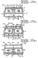
- FIGs. 10a through 10f schematically illustrates relative positions of the multi-piston subassembly 50 and the flow control means 266 within the operating chamber 22, at specific locations during one complete rotation of the crankshafts 52 and 54.
- the first 180 degrees of the crankshafts 52 and 54 rotation are identified as period or step X in Fig. 9.
- Fig. 10a schematically illustrates approximately the -450 degree position of the crankshafts 52 and 54 or the start of the step X as indicated in Fig.9.
- Fig 10b schematically illustrates approximately the -360 degree position of crankshafts 52 and 54.
- Fig 10c schematically illustrates approximately the -270 degree position of crankshafts 52 and 54.
- the low pressure piston assembly 56 is moved in the first direction in the operating chamber 22 increasing the volume of the intake chamber 144, inducting a charge of air into the intake chamber 144 and reducing the volume in the exhaust chamber 146, exhausting a charge of exhaust gas from the exhaust chamber 146.
- the high piston assemblies 58 and 60 are moved in the bores 178 and 186 compressing another charge of air in the combustion space 254. As illustrated in Fig.
- fuel is introduced into the combustion space 254 forming a combustible mixture of fuel and air which auto ignites forming expanding exhaust gas driving the high pressure piston assemblies 58 and 60 in their respective bores 178 and 186 and transmitting the energy to the crankshafts 52 and 54.
- Fig. 10d schematically illustrates approximately the -225 degree position of the crankshafts 52 and 54.
- step Y the low pressure piston assembly 56 is moved in the second direction compressing the charge of air in the intake chamber 144.
- the high pressure piston assemblies 58 and 60 continue to be driven in their respective bores 178 and 186 transmitting energy to the crankshafts 52 and 54 while transferring the expanding exhaust gas to the exhaust chamber 146.
- Fig. 10e schematically illustrates approximately the -180 degree position of the crankshafts 52 and 54 or start of the step Z.
- Fig 10f schematically illustrates approximately the -135 degree position of crankshafts 52 and 54.
- step Z the low pressure piston assembly 56 continues to be driven in the second direction compressing the charge of air in the intake chamber 144 while transferring the charge of compressed air into the combustion space 254.
- the high pressure piston assemblies 58 and 60 are moved in their respective bores 178 and 186 further compressing the E charge of compressed air in the combustion space 254.
- the pressure caused by the expansion of the exhaust gas in the exhaust chamber assists in driving the low pressure piston assembly 56 in the second direction transmitting energy to the crankshafts 52 and 54.
- the exhaust valve actuation means 560 controllably displaces the exhaust valve sealing face 370 of each exhaust valve 358 away from its respective exhaust valve sealing surface 352 during each revolution of the crankshafts 52 and 54 and Fat a preselected range of movement of the low pressure piston assembly 56 in the operating chamber 22.
- the exhaust valves 358 are maintained against their respective exhaust valve seating surface 352 by the bias of exhaust valve springs 386 and the pressure of compression of air, combustion and expansion of exhaust gas in the combustion space 254.
- hydraulic fluid is pumped from the outer exhaust valve pump chambers 382 by the exhaust valve pistons 380 and transferred to the exhaust valve transfer pump chamber 568 by the exhaust valve transfer conduit 570.
- the exhaust valves 358 are timed, as shown in Fig. 9, to be displaced from their respective exhaust valve seating surfaces 352 at the beginning of step H for a duration of approximately 90 degrees of crankshafts 52 and 54 rotation.
- hydraulic fluid is pumped from the exhaust valve fluid actuator chamber 582 by the exhaust valve actuator piston 580 of the exhaust valve actuator cylinder assembly 574, to the outer exhaust valve pump chambers 382 by way of the branch conduit 592 and the exhaust valve transfer conduit 570.
- the exhaust valve actuator piston 580 is displaced by the exhaust valve cam follower 582 which rides on the exhaust valve actuator cam 588 driven by the engine 8.
- the exhaust valve actuator cam 588 makes one revolution for each revolution of the crankshafts 52 and 54.
- the additional volume of hydraulic fluid contributed by the action of the exhaust valve actuator piston 580 increases the volume of hydraulic fluid in the outer exhaust valve pump chambers 382 and acts on the ends of exhaust valve pump pistons 380, overcoming the bias of the exhaust valve springs 386 and the pressure from the expanding exhaust gas in the combustion chamber 254 acting on the ends of the exhaust valve head portions 368 within the combustion chamber, displacing the exhaust valves 358 from their respective seating surfaces 352.
- the additional volume of hydraulic fluid from the exhaust valve fluid actuator chamber 582 is forced to be transmitted to the outer exhaust valve pump chambers 382 since, the volume of the exhaust valve transfer pump chamber 568 cannot be increased.
- the volume of the exhaust valve transfer pump chamber 568 is being controllably reduced and the volume of the outer exhaust valve pump chambers 382 can be increased merely by displacing the exhaust valves 358 from their respective exhaust valve seating surfaces 352. This is accomplished by overcoming the bias of the exhaust valve springs 386 and the pressure from the expanding exhaust gas in the cr 254 acting on the ends of the exhaust valve head portions 368 within the combustion chamber 254.
- the scavenge valve actuation means 594 controllably displaces the scavenge valve sealing face 438 of each scavenge valve 430 away from their respective scavenge valve seating surfaces 418 and 426 during each revolution of the crankshafts 52 and 54.
- the scavenge valves 430 are maintained against their respective scavenge valve seating surfaces 418 and 426 by the bias of scavenge valve springs 454 and the pressure of the expansion of exhaust gas in the exhaust chamber 146.
- the scavenge valves 430 are timed, as shown in Fig. 9, to be displaced from their respective scavenge valve seating surfaces 418 and 426 at the beginning of step I for a duration of approximately 180 degrees of crankshafts 52 and 54 rotation.
- hydraulic fluid is pumped from the scavenge valve fluid actuator chamber 604 by the scavenge valve actuator piston 602 of the scavenge valve actuator cylinder assembly 596, to the outer scavenge valve pump chambers 450 by way of the conduit 614.
- the scavenge valve actuator piston 602 is displaced by the scavenge valve cam follower 608 which rides on the scavenge valve cam 610 driven by the engine 8.
- the scavenge valve cam 610 makes one revolution for each revolution of the crankshafts 52 and 54.
- the additional volume of hydraulic fluid contributed by the action of the scavenge valve actuator piston 602 increases the volume and pressure of the hydraulic fluid in the outer scavenge valve pump chambers 450.
- This increasing pressure acts on the ends of scavenge valve pump pistons 448, overcoming the bias of the scavenge valve springs 454 and the pressure from the expanding exhaust gas in the exhaust chamber 146 acting on the ends of the valve head portions 436 within the exhaust chamber, displacing the scavenge valves 430 from their respective seating surfaces 418 and 426.
- the fuel introducing system 455 controllably injects fuel into the combustion space during each revolution of the crankshafts 52 and 54 and at approximately the beginning of step E as shown on Fig. 9.
- the fuel injector nozzle assembly 456 is mounted on the low pressure piston assembly 56 and communicates with the combustion space 254 as shown on Figs. 7 and 8.
- the control member 464 is reciprocally positioned in the fuel pump cylinder 474 and connected for movement with the low pressure piston assembly 56, controllably delivering fuel under high pressure from the fuel pump assembly 460 to the fuel injector nozzle assembly 456 in response to reciprocation of the low pressure piston assembly 56 in the first direction.
- the inner fuel pump chamber 498 is filled with fuel from the source 500 via the fuel line 502, the transverse passage 504, the fuel transfer passage 506, the first port 510, the fill passage 518, and the second port 522 as the low pressure piston assembly 56 is moved in the second direction during step B as shown on Fig. 9.
- fuel is transferred from the inner fuel pump chamber 498 to the outer fuel pump chamber 494 by inward movement of the fuel pump piston portion 480 in the fuel pump cylinder 474.
- the fuel is transferred by way of the fuel transfer passage 506, the first fuel port 510, the second fuel port 522, the fill passage 518, and the transverse passage 504. Since the cross-sectional area of the fuel pump cylinder 474 in each of the inner fuel pump chamber 498 and outer fuel pump chamber 494 is the same and the cross-section area of the inner rod portion 482 and outer rod portion 476 the is the same, then the volume of fuel being transferred between the inner fuel pump chamber and the outer fuel pump chamber is equal.
- both transfer ports 510 and 522 are blocked by the cylindrical land surface 490 and the solenoid actuator valve 516 is energized, extending the blocking piston 514 into the fuel transfer passage 506 blocking the fuel transfer passage.
- the solenoid actuator valve 516 is energized, extending the blocking piston 514 into the fuel transfer passage 506 blocking the fuel transfer passage.
- the fuel is communicated under high pressure to the fuel injector nozzle assembly 456 by way of the axial fuel supply passage 548.
- the high pressure fuel acts on the injector valve 540 within the injector valve bore 534, overcoming the bias of the injector valve spring 538 moving the injector valve 540 away from the spray orifice means 536 and allowing the injection of fuel into the combustion chamber 254 through the spray orifice means in a conventional manner.
- the solenoid valve 516 is actuated to move the passage blocking piston 514 out of the fuel transfer passage 506, unblocking the fuel transfer passage reducing the pressure in the fuel pump chamber 498 and allowing the fuel to be transferred to the outer fuel pump chamber 494.
- the engine 8 is in complete balance with respect to forces and couples in the longitudinal, transverse, and perpendicular directions. This is achieved by having the rear first and third timing and balancing gears 74 and 96 in mesh with one another and the front second and fourth timing and balancing gears 80 and 100 in mesh with one another and having respective balance weights 78, 82, 98, and 102 positioned approximately 180 degrees away from their respective adjacent crankpins 68 and 90.
- the maximum volume of the exhaust chamber 146 exceeds that of the intake chamber 144, this serves to reduce exhaust gas pressure and temperature when the scavenge valves 430 opens. In this manner efficiency is increased and noise is reduced relative to more conventional engines for which induction and exhaust volumes are equal.
- the dual compression, dual expansion engine 8 is less than half the volume, is more efficient because it can use higher compression ratios with a more compact combustion chamber, and it has lower NO x emissions because it achieves high levels of exhaust retention without a loss of power.
Landscapes
- Engineering & Computer Science (AREA)
- Mechanical Engineering (AREA)
- General Engineering & Computer Science (AREA)
- Chemical & Material Sciences (AREA)
- Combustion & Propulsion (AREA)
- Cylinder Crankcases Of Internal Combustion Engines (AREA)
- Fuel-Injection Apparatus (AREA)
- Output Control And Ontrol Of Special Type Engine (AREA)
- Combustion Methods Of Internal-Combustion Engines (AREA)
Claims (75)
- Verbrennungsmaschine (8) die folgendes aufweist:ein Gehäuse (10), welches eine Arbeitskammer (22) definiert und mit einem Einlaß oder Induktionsdurchlaß (282-286) und mit einem Spüldurchlaß (414-422);eine Mehrfachkolbenunteranordnung (50) die folgendes aufweist:eine erste Kolbeanordnung (55) hin und herbewegbar angeordnet in der Arbeitskammer (22), wobei die erste Kolbenanordnung (56) einen Körper (110) aufweist, der eine erste und zweite koaxial ausgerichtete Bohrung (178-186) definiert, eine zweite und dritte Kolbenanordnung (58-60) hin und her bewegbar angeordnet in einer entgegengesetzten Beziehung in den ersten und zweiten Bohrungen (178-186) und mit dem Körper (110) einen Verbrennungsraum (254) dazwischen definierend, eine erste und zweite Kurbelwelle (52-54) jeweils direkt mit den zweiten und dritten Kolbenanordnungen (58-60) verbunden, um Leistung außerhalb davon ansprechend auf die Verbrennung in dem Verbrennungsraum (254) zu liefern.
- Verbrennungsmaschine (8) nach Anspruch 1, wobei das Gehäuse (10) eine Vielzahl von identischen transversal orientierten und longitudinal beabstandeten Arbeitskammern 22 aufweist.
- Verbrennungsmaschine (8) nach Anspruch 2, wobei das Gehäuse (10) einen ersten Gehäuseteil (12) und einen zweiten Gehäuseteil (14) entfernbar aneinander befestigt aufweist.
- Verbrennungsmaschine (8) nach Anspruch 3, wobei der erste Gehäuseteil (12) einen ersten offenen im allgemeinen länglichen Hohlraum (18) definiert mit einer vorgewählten Breite Länge und Höhe, und wobei der zweite Gehäuseteil (14) einen zweiten offenen im allgemeinen länglichen Hohlraum (20) definiert der eine vorgewählte Breite Länge und Höhe besitzt.
- Verbrennungsmaschine (8) nach Anspruch 4, wobei der erste Hohlraum (18) durch ein paar von im allgemeinen parallelen Seitenoberflächen (24, 26) definiert ist, ein Paar von im allgemeinen halbzylindrischen Endoberflächen (28-30) die zusammenlaufend die Seitenoberflächen (24-26) verbinden, und eine Deckenoberfläche (32), und wobei ferner der zweite Hohlraum (20) durch ein Paar von im allgemeinen parallelen Seitenoberflächen (40-42) definiert ist, ein Paar von im allgemeinen halbzylindrischen Endoberflächen (44-46) und eine Bodenoberfläche (48).
- Verbrennungsmaschine (8) nach Anspruch 5, wobei die ersten und zweiten Hohlräume (18-20) in einer entgegengesetzt liegenden ausgerichteten Beziehung angeordnet sind, um die Arbeitskammer (22) zu bilden.
- Verbrennungsmaschine (8) nach Anspruch 6, wobei die Breite des zweiten Hohlraums (20) die gleiche ist wie die Breite des ersten Hohlraums (18).
- Verbrennungsmaschine (8) nach Anspruch 7, wobei die Länge des zweiten Hohlraums (20) größer ist als die Länge des ersten Hohlraums (18).
- Verbrennungsmaschine (8) nach Anspruch 8, wobei die Höhe der ersten und zweiten Hohlräume (18-20) die gleiche ist.
- Verbrennungsmaschine (8) nach Anspruch 9, wobei die erste Kurbelwelle (52) eine Vielzahl von in Längsrichtung ausgerichteten Hauptlagerschalen (62) aufweist, mit einer Mittelachse (66) angeordnet im allgemeinen unter einem rechten Winkel gegenüber den Seitenoberflächen (24-26-40-42) der Hohlräume (18-20) und einen Kurbelwellenstift (68) und wobei die zweite Kurbelwelle (54) eine Vielzahl von longitudinal ausgerichteten Hauptlagerschalen (84) aufweist, mit einer Mittelachse (88) und einem Kurbelwellenstift (90), wobei die Mittelachsen (66-88) der Lagerschalen (62-84) der ersten und zweiten Kurbelwellen (52-54) parallel verlaufen.
- Verbrennungsmaschine (8) nach Anspruch 10, wobei ein erstes Zeitsteuer- und Ausgleichsgetriebe bzw. Zahnrad (74) ein Ausgleichsgewicht (78) besitzt, und zwar positioniert annähernd 180 Grad weg von dem benachbarten Kurbelwellenstift (68), und zwar verbunden mit einem hinteren Ende (76) der ersten Kurbelwelle (52), und wobei ein drittes Zeitsteuer- und Ausgleichszahnrad (96) mit einem Ausgleichsgewicht (98) positioniert annähern 180 Grad weg von dem benachbarten Kurbelwellenstift (90) verbunden ist mit einem hinteren Ende (97) der zweiten Kurbelwelle (54), wobei die ersten und dritten Zeitsteuer- und Ausgleichszahnräder (74-96) miteinander in Eingriff stehen und eine Phasengegendrehung der ersten und zweiten Kurbelwellen (52-54) aufprägen.
- Verbrennungsmaschine (8) nach Anspruch 11, wobei ein zweites Zeitsteuer- und Ausgleichszahnrad (80) ein Ausgleichsgewicht (82) aufweist, und zwar positioniert annähern 180 Grad weg von dem benachbarten Kurbelwellenstift (68) und verbunden mit einem vorderen Ende (81) der ersten Kurbelwelle (52) und mit einem vierten Zeitsteuer- und Ausgleichszahnrad (100) und mit einem Ausgleichsgewicht (102) positioniert annähern 180 Grad weg von dem benachbarten Kurbelwellenstift (90), und zwar verbunden mit einem hinteren Ende (101) der zweiten Kurbelwelle (54), wobei die zweiten und vierten Zeitsteuer- und Ausgleichszahnräder (80-100) miteinander in Eingriff stehen und eine Phasengegendrehung der ersten und zweiten Kurbelwellen (52-54) aufprägen.
- Verbrennungsmaschine (8) nach Anspruch 11, wobei der Körper (110) der ersten Kolbenanordnung (56) eine im allgemeinen längliche Gestalt besitzt, und zwar mit einem Paar von im allgemeinen parallelen Seitenoberflächen (112-114), einen ersten Endteil (116), einen zweiten Teil (118), eine obere Arbeitsoberfläche (140) und eine Bodenarbeitsoberfläche (142).
- Verbrennungsmaschine (8) nach Anspruch 13, wobei die oberen und unteren Arbeitsoberflächen (140-142) des Körpers (110) der ersten Kolbenanordnung (156) im allgemeinen parallel zueinander verlaufen, im allgemeinen senkrecht zu den Seitenoberflächen (112-114) davon.
- Verbrennungsmaschine (8) nach Anspruch 14, wobei der erste Endteil (116) des Körpers (110) eine erste halbzylindrischen Endoberfläche (120) aufweist, und wobei der zweite Endteil (118) eine erste halbzylindrischen Endoberfläche (130) besitzt.
- Verbrennungsmaschine (8) nach Anspruch 15, wobei ein Band (148) sich vollständig um den Umfang der Seitenoberflächen (112, 114) und die ersten halbzylindrischen Endoberflächen (120) bis (130) der ersten und zweiten Endteile (116 bis 118) benachbart zu den oberen Arbeitsoberflächen (140) herumerstreckt, wobei das Band (148) eine Vielzahl von Ringnuten (150) definiert und eine Vielzahl von Abdichtringen (152) in den Ringnuten (150) aufgenommen ist.
- Verbrennungsmaschine (8) nach Anspruch 16, wobei der erste Endteil (116) eine zweite halbzylindrische Endoberfläche (122) aufweist, die sich nach außen über die erste halbzylindrische Endoberfläche (120) erstreckt, um einen Flanschteil (126) zu bilden, und wobei der zweite Endteil (118) einen zweiten halbzylindrischen Endteil (132) aufweist, der sich nach außen über die erste halbzylindrische Endoberfläche (130) des zweiten Endteils (118) hinauserstreckt, um einen Flanschteil (134) zu bilden.
- Verbrennungsmaschine (8) nach Anspruch 17, wobei ein Band (154) sich vollständig um den Umfang der Seitenoberflächen (112-114) und die zweiten halbzylindrischen Endoberflächen (122-132) der ersten und zweiten Endteile (116-118) benachbart zu der unteren Arbeitsoberfläche (142) erstreckt, und wobei das Band (154) eine Vielzahl von Ringnuten (156) definiert und wobei ferner eine Vielzahl von Abdichtringen (158) in den Ringnuten (156) aufgenommen ist.
- Verbrennungsmaschine (8) nach Anspruch 18, wobei ein erster Kurbelwellenzwischenraumdurchlaß (160) in dem Körper (110) benachbart zum ersten Endteil (116) definiert ist, wobei der erste Zwischenraumdurchlaß (160) im allgemeinen senkrecht zu den Seitenoberflächen (112-114) verläuft und annähernd mittig zwischen den oberen und unteren Arbeitsoberflächen (140-142), und wobei die erste Kurbelwelle (52) betriebsmäßig in dem ersten Zwischenraumdurchlaß (160) angeordnet ist, ohne Kontakt damit zu machen.
- Verbrennungsmaschine (8) nach Anspruch 19, wobei ein zweiter Kurbelwellenzwischenraumdurchlaß (162) in dem Körper (110) der ersten Kolbenanordnung (56) benachbart zum zweiten Endteil (118) definiert ist, und wobei der zweite Zwischenraumdurchlaß (162) im allgemeinen senkrecht zu den Seitenoberflächen (112-114) und annähernd mittig zwischen den oberen und unteren Arbeitsoberflächen (140-142) angeordnet ist, und wobei die zweite Kurbelwelle (54) betriebsmäßig in dem zweiten Zwischenraumdurchlaß (162) angeordnet ist, ohne Kontakt damit zu machen.
- Verbrennungsmaschine (8) nach Anspruch 1, wobei die erste Kolbebohrung (178) eine Endoberfläche (180) aufweist, die sich von einer ersten zylindrischen Endoberfläche (120) eines ersten Endteils (116) nach innen erstreckt, und zwar mit der Mittelachse (182) auf einer ersten Ebene angeordnet, die im wesentlichen parallel zu und mittig zwischen Seitenoberflächen (112-114) des Körpers (110) verläuft und auf einer zweiten Ebene die im wesentlichen parallel zu und mittig zwischen oberen und unteren Arbeitsoberflächen (140-142) verläuft.
- Verbrennungsmaschine (8) nach Anspruch 21, wobei die zweite Kolbenbohrung (186) eine Mittelachse (190) und eine Endoberfläche (188) aufweist, wobei die zweite Kolbenbohrung (186) sich von der ersten halbzylindrischen Endoberfläche (130) des zweiten Endteils (118) sich nach innen erstreckt
- Verbrennungsmaschine (8) nach Anspruch 22, wobei die zweiten und dritten Kolbenanordnungen (56-58) identisch sind und jeweils einen Körperteil (198) aufweisen, sowie Mittel (224) zur Verbindung der entsprechenden zweiten und dritten Kolbenanordnungen (56-58), und zwar direkt mit den ersten und zweiten Kurbelwellen (52-54).
- Verbrennungsmaschine (8) nach Anspruch 21, wobei der Körperteil (198) ein im allgemeinen zylindrisches Kopfende (208) aufweist mit einer Arbeitsoberfläche (210) die zu entsprechenden Endoberflächen (180-188) der ersten und zweiten Kolbenbohrungen (178-146) weist und mit einem Kupplungsende (212) welches eine halbzylindrische Oberfläche (220) definiert, wobei die Mittel (204) zur Verbindung der entsprechenden zweiten und dritten Kolbenanordnungen (56-58) direkt mit den ersten und zweiten Kurbelwellen (52-54) das Kupplungsende (212) umfassen, eine Lagerkappe (200) die eine halbzylindrische Oberfläche 222 definiert, ein Paar von Lagerschalen (202-204), angeordnet in den halbzylindrischen Oberflächen (220-222) des Kupplungsendes (212) und der Lagerkappe (200) und eine Vielzahl von Befestigern (206) zur entfernbaren Befestigung der Lagerkappe (200) am Kupplungsende (212).
- Verbrennungsmaschine (8) nach Anspruch 24, wobei das Kopfende (208) jeder der zweiten und dritten Kolbenanordnungen (56-58) eine Vielzahl von Dichtringnuten (216) definiert, die geeignet sind, eine Vielzahl von Dichtringen (218) aufzunehmen, und zwar zum Abdichteingriff mit den entsprechenden ersten und zweiten Kolbenbohrungen (178-186).
- Verbrennungsmaschine (8) nach Anspruch 24, mit Strömungssteuermitteln (266) zum selektiven Verbinden des Induktions- oder Einlaßdurchlasses (282-286) mit der Einlaßkammer (144), die Einlaßkammer (144) mit dem Verbrennungsraum (254), des Verbrennungsraumes (254) mit der Ausstoßkammer (146) und der Ausstoßkammer (146) mit dem Spüldurchlaß (414-422).
- Verbrennungsmaschine (8) nach Anspruch 26, wobei die Strömungssteuermittel (266) Induktions- oder Eingabemittel (268) aufweisen zum selektiven Verbinden des Einlaßdurchlasses (282-286) mit der Einlaßkammer (144).
- Verbrennungsmaschine (8) nach Anspruch 27, wobei das Gehäuse (10) einen Einlaßanschluß (288) definiert und wobei die Induktions- oder Einlaßmittel (268) eine Einlaßventilanordnung (294) aufweisen, und zwar betriebsmäßig angeordnet in dem Einlaßanschluß (288).
- Verbrennungsmaschine (8) nach Anspruch 28, wobei eine Einlaßventilsitzoberfläche (290) in der Deckenoberfläche (32) des Gehäuses (10) definiert ist, und zwar um den Einlaßanschluß (288) herum, und wobei die Einlaßventilanordnung (294) ein Einlaßventil (296) aufweist, mit einem Einlaßventilschaft (300) und einem Einlaßventilkopfteil (302) angeordnet an einem Ende des Einlaßventilschaftes (300), wobei der Einlaßventilkopfteil (302) eine Induktionsventilabdichtoberfläche (304) definiert und von einer Dimension ist, die ausreicht, um den abdichtenden Sitz der Einlaßventilabdichtstirnfläche (304) auf der Einlaßventilsitzoberfläche (290) vorzusehen.
- Verbrennungsmaschine (8) nach Anspruch 29, wobei die Einlaßventilanordnung (294) eine Einlaßventilfeder (298) aufweist, um das Einlaßventil (296) gegen die Einlaßventilsitzoberfläche (290) zu drücken.
- Verbrennungsmaschine (8) nach Anspruch 28, wobei das Gehäuse (10) eine Vielzahl von Einlaßanschlüssen (288) definiert, und wobei eine weitere Einlaßventilanordnung (294) betriebsmäßig in jedem der Einlaßanschlüsse (288) angeordnet ist.
- Verbrennungsmaschine (8) nach Anspruch 31, wobei eine weitere Einlaßventilsitzoberfläche (290) in der Deckenoberfläche (32) des Gehäuses (10) um jeden der Einlaßanschlüsse (288) definiert ist, und wobei die weitere Einlaßventilanordnung (294) ein weiteres Einlaßventil (296) aufweist, mit einem weiteren Einlaßventilschaft (300) und einen weiteren Einlaßventilkopfteil (302) angeordnet an einem Ende des weiteren Einlaßventilschaftes (300), wobei der weitere Einlaßventilkopfteil (302) eine weitere Einlaßventilabdichtstirnfläche (304) definiert und eine Dimension besitzt ausreichend für den abdichtenden Sitz der weiteren Einlaßventiloberfläche (92).
- Verbrennungsmaschine (8) nach Anspruch 32, wobei die weitere Einlaßventilanordnung (294) eine weitere Einlaßventilfeder (298) aufweist, um das weitere Einlaßventil (296) gegen die weitere Einlaßventilsitzoberfläche (290) zu drücken.
- Verbrennungsmaschine (8) nach Anspruch 26, wobei die Strömungssteuermittel (266) Mittel (270) aufweisen zum selektiven Verbinden der Einlaßkammer (144) mit dem Verbrennungsraum (254).
- Verbrennungsmaschine (8) nach Anspruch 30, wobei die Einlaßventilmittel (270) eine Einlaßventilanordnung (316) aufweisen.
- Verbrennungsmaschine (8) nach Anspruch 35, wobei der Körper (110) der ersten Kolbenanordnung (56) einen ersten Einlaßanschluß (306) mit einer Mittelachse (310) definiert, wobei der erste Einlaßanschluß (306) sich zwischen der oberen Arbeitsoberfläche (140) und einer oberen Oberfläche oder Oberseite (256) des Verbrennungsraums (254) erstreckt und die Einlaßventilanordnung (316) betriebsmäßig in dem ersten Einlaßanschluß (306) angeordnet ist.
- Verbrennungsmaschine (8) nach Anspruch 36, wobei eine Einlaßventilsitzoberfläche (314) definiert in der Ventilanordnung (316) ein Einlaßventil (320) aufweist mit einem Einlaßventilschaft (324), einem Einlaßventilkopfteil (326) angeordnet an dem Ende des Einlaßventilschaftes (324), wobei das Elnlaßventilkopfteil (326) eine Einlaßventilsitzstirnfläche (328) definiert, und wobei ferner eine Einlaßventilfeder (322) zwischen dem Körper (110) und dem Ende des Einlaßventilschaftes (324) angeordnet ist, um die Einlaßventilsitzstirnfläche (328) gegen die Einlaßventilsitzoberfläche (314) zu drücken.
- Verbrennungsmaschine (8) nach Anspruch 37, wobei der Körper (110) einen zweiten Einlaßanschluß (308) definiert, und zwar mit einer Mittelachse (312), und wobei der zweite Einlaßanschluß (308) sich zwischen der.oberen Arbeitsoberfläche (140) und der Oberseite (256) des Verbrennungsraumes (254) erstreckt, und wobei die Einlaßventilanordnung (316) betriebsmäßig in dem zweiten Einlaßanschluß (308) angeordnet ist.
- Verbrennungsmaschine (8) nach Anspruch 38, wobei eine weitere Einlaßventilsitzoberfläche (314) in der Oberseite (256) um den zweiten Anschluß (308) definiert ist, und wobei die weitere Einlaßventilanordnung (316) ein weiteres Einlaßventil (320) mit einem weiteren Einlaßventilschaft (324) aufweist, und zwar ferner mit einem weiteren Einlaßventilkopfteil angeordnet an dem Ende des weiteren Einlaßventilschaftes (324), und zwar definierend eine weitere Einlaßventilsitzstirnfläche oder Sitzfläche (328), und wobei ferner eine weitere Einlaßventilfeder (322) zwischen dem Körper (110) und dem Ende des weiteren Einlaßventilschaftes (324) angeordnet ist, um die weitere Einlaßventilsitzstirnfläche gegen die Einlaßventilsitzoberfläche (314) zu drükken.
- Verbrennungsmaschine (8) nach Anspruch 39, wobei die Mittelachsen (310-312) der ersten und zweiten Einlaßanschlüsse (306-308) im allgemeinen in Längsrichtung ausgerichtet sind zwischen den Seitenoberflächen (112-114) des Körpers (110) und annähern mittig zwischen den Endoberflächen (120-130) davon.
- Verbrennungsmaschine (8) nach Anspruch 40, wobei die Strömungssteuermittel (226) Auslaßmittel (272) aufweisen zum selektiven Verbinden des Verbrennungsraumes (254) mit der Ausstoß- oder Auslaßkammer (146).
- Verbrennungsmaschine (8) nach Anspruch 41, wobei die Auslaßmittel (272) ein Ventilbetätigungsmechanismus (356) aufweisen, wobei der erste Ventilbetätigungsmechanismus (356) ein Auslaßventil (358) aufweist, Auslaßventiltragmittel (360) zum hin und her gehenden Tragen des Auslaßventils (358) am Gehäuse (10) und zur Bewegung mit einer ersten Kolbenanordnung (56), und Auslaßventilbetätigungsmittel (560) zur Betätigung des Auslaßventils (358).
- Verbrennungsmaschine (8) nach Anspruch 13, wobei der Körper (110) des ersten Kolbens (56) einen Auslaßanschluß (344) definiert, und zwar mit einer Mittelachse (348), wobei der erste Auslaßanschluß (344) sich zwischen der Bodenarbeitsoberfläche (142) und einer Bodenoberfläche (258) des Verbrennungsraums (254) erstreckt, und das Auslaßventil (358) betriebsmäßig in dem ersten Auslaßanschluß (344) angeordnet ist.
- Verbrennungsmaschine (8) nach Anspruch 43, wobei die Auslaßventilsitzoberfläche (352) in der Bodenoberfläche (258) am ersten Auslaßanschluß (344) definiert ist, wobei das Auslaßventil (358) einen Auslaßventilschaft (366) und einen Auslaßventilkopfteil (368) aufweist, und zwar eine Auslaßventilabdichtstirnfläche (370) definierend, und von einer Dimension ausreichend zum abdichtenden Sitzen der Auslaßventildichtstirnfläche (370) auf der Auslaßventilsitzoberfläche (352).
- Verbrennungsmaschine (8) nach Anspruch 43, wobei die Auslaßventiltragmittel (360) eine Auslaßventilführung (376) aufweisen, und zwar angebracht in einem Auslaßventilpumpenzylinder (378) definiert in der Bodenoberfläche (48) des Gehäuses (10) und mit einem Auslaßventilkolben (380) angebracht an einem Ende des Auslaßventilschaftes (366) entgegengesetzt zu dem Auslaßventilkopfteil (368), wobei die Auslaßventilführung (376) den Auslaßventilschaft (366) und den Auslaßventilkolben (380) umfaßt, welch letzterer geeignet ist für eine hin und her gehende Gleitbewegung in dem Auslaßventilpumpenzylinder (378).
- Verbrennungsmaschine (8) nach Anspruch 45, wobei eine Auslaßventilpumpenkammer (382) in dem Auslaßventilpumpenzylinder (378) nach außen gegenüber dem Auslaßventilkolben (380) definiert ist, wobei ein Auslaßventilpumpenzylinder (378) nach innen gegenüber dem Auslaßventilkolben (380) und eine Auslaßventilfeder (386) angeordnet ist, und zwar in der Auslaßventilfederkammer (364) und sich zwischen der Auslaßventilführung (376) und dem Auslaßventilkolben (380) erstreckend, um die Auslaßventilabdichtstirnfläche (370) des Auslaßventils (358) gegen die Auslaßventilsitzoberfläche (352) zu drücken, bis der Auslaßventilkopfteil (368) weg von der Auslaßventilsitzoberfläche (252) bewegt wird.
- Verbrennungsmaschine (8) nach Anspruch 46, wobei die Auslaßventilbetätigungsmittel (560), Übertragungs- oder Transfermittel (562) aufweisen, zum Übertragen oder Transfer von Strömungsmittel zwischen den Transfermitteln (562) und der Auslaßventilpumpenkammer (382), wobei die Transfermittel (562) einen Transferpumpenzylinder (564) aufweisen, und zwar definiert in einem Pumpenkörper (462) entfernbar befestigt an dem Gehäuse (10), wobei ferner ein Steuerglied (464) zur Bewegung mit der ersten Kolbenanordnung (56) verbunden ist, und wobei eine Auslaßventilbetätigeranordnung (574) vorgesehen ist und das Steuerventil (464) ein Stangenteil (478) aufweist, der sich in den Transferpumpenzylinder (564) erstreckt, und wobei ferner ein Transferpumpenkolben (566) an einem Ende des Stangeteils (478) angerbacht ist, und zwar für eine hin und her gehende Bewegung damit, und wobei schließlich eine Transferpumpenkammer (564) in dem Transferpumpenzylinder (564) definiert ist, und zwar zwischen dem Transferpumpenkolben (566) und einem Ende der Transferpumpenkammer (564) mit der Querschnittsfläche der Transferpumpenkammer (564) gleich der Querschnittsfläche der Auslaßventilpumpenkammer (382), wobei eine Transfer- oder Übertragungsleitung (570) die Transferpumpenkammer (564) mit der Auslaßventilpumpenkammer (382) verbindet.
- Verbrennungsmaschine (8) nach Anspruch 47, wobei die Auslaßventilbetätigungszylinderanordnung (574) einen Auslaßventilbetätigerkörper (576) aufweist, der eine Auslaßventilbetätigerkolbenbohrung (578) definiert, wobei ein Auslaßventilbetätigerkolben (580) gleitbar in der Auslaßventilbetätigerbohrung (578) angeordnet ist, und wobei eine Auslaßventilbetätigerströmungsmittelbetätigerkammer (582) ein vorgewähltes Volumen besitzt, und zwar definiert in der Auslaßventilbetätigerkolbenbohrung (578) zwischen dem Auslaßventilbetätigerkolben (580) und einem Ende der Auslaßventilbetätigerkammer (582), wobei eine Auslaßventilkolbenstange (584) mit dem Auslaßventilbetätigerkolben (580) verbunden ist, und zwar entgegengesetzt zu der Auslaßventilbetätigerkammer (582), wobei ferner ein Auslaßventilnockenfolger (586) mit einem Ende der Auslaßventilstange (584) verbunden ist, und auf einem Auslaßventilnocken (588) läuft, der durch den Motor (8) angetrieben ist, und wobei schließlich eine Auslaßventilbetätigerfeder (590) in der Auslaßventilbetätigerkammer (582) angeordnet ist, und zwar zwischen angeordnet zwischen einem Auslaßventilbetätigerkolben (580) und dem Ende der Auslaßventilbetätigerkammer (582) zum Vorspannen des Auslaßventilnockenfolgers (586) gegen den Auslaßventilnocken (588), wobei der Auslaßventilbetätigerkolben (580) ansprechend auf die Bewegung des Auslaßventilnockenfolgers (586) in Betrieb kommt, um Strömungsmittel von Auslaßventilbetätigerkammer (582) zu der Auslaßventilpumpenkammer (382) zu verschieben, und zwar zur steuerbaren Versetzung der Auslaßventilabdichtstirnfläche (370) des Auslaßventils (358) weg von der Auslaßventilsitzoberfläche (352) zu einer vorgewählten Zeit.
- Verbrennungsmaschine (8) nach Anspruch 48, wobei der Auslaßventilnocken (588) für jede Umdrehung der Kurbelwelle (82) eine Umdrehung macht.
- Verbrennungsmaschine (8) nach Anspruch 49, wobei der Körper (110) einen zweiten Auslaßanschluß (346) definiert, und zwar mit einer Mittelachse (350), wobei die zweite Auslaßanschlußbodenarbeitsoberfläche (142) des Körpers (110) und ein weiteres Auslaßventil (358) betriebsmäßig in dem zweiten Auslaßanschluß (346) angeordnet sind.
- Verbrennungsmaschine (8) nach Anspruch 50, wobei eine weitere Auslaßventilsitzoberfläche (352) in der Bodenoberfläche (258) um den zweiten Auslaßanschluß (344) herum definiert ist, wobei das weitere Auslaßventil (358) einen weiteren Auslaßventilschaft (366) und einen weiteren Auslaßventilkopfteil (368) aufweist, und zwar eine weitere Auslaßventildichtstirnfläche (370) definierend, und zwar mit einer Dimension ausreichend zum abdichtenden Sitzen der weiteren Auslaßventildichtstirnfläche (370) auf der weiteren Auslaßventilsitzoberfläche (352).
- Verbrennungsmaschine (8) nach Anspruch 51, wobei die Mittelachsen (310-312) der ersten und zweiten Auslaßanschlüsse (348-350) im allgemeinen ausgerichtet sind zwischen den Seitenoberflächen (112-114) des Körpers (110) und zwar annähernd mittig zwischen den Endoberflächen (120-130).
- Verbrennungsmaschine (8) nach Anspruch 52, wobei die Mittelachsen (310-312) der ersten und zweiten Auslaßanschlüsse (348-350) und die Mittelachsen (310-312) der ersten und zweiten Einlaßanschlüsse (306-308) im allgemeinen axial ausgerichtet sind.
- Verbrennungsmaschine (8) nach Anspruch 53, wobei der Auslaßventilbetriebsmechanismus (356) ein weiteres Auslaßventil (358) aufweist, und zwar betriebsmäßig angeordnet in dem zweiten Auslaßventilanschluß (346), wobei das weitere Auslaßventil (358) einen weiteren Auslaßventilschaft (366) aufweist, und einen weiteren Auslaßventilkolben (380) angebracht an einem Ende des weiteren Auslaßventilschaftes (366) und hin und her bewegbar angeordnet in einem weiteren Auslaßventilpumpenzylinder (378) angeordnet in weiteren Auslaßventiltragmitteln (360), ferner mit einer weiteren Auslaßventilpumpenkammer (382) definiert in dem weiteren Auslaßventilpumpenzylinder (378) nach außen gegenüber dem weiteren Auslaßventilkolben (380) und betriebsmäßig verbunden mit der Auslaßventilpumpenkammer (382) des Auslaßventils (358) in dem ersten Auslaßanschluß (348) derart, daß das weitere Auslaßventil (358) gleichzeitig öffnet und schließt mit dem Auslaßventil (358) des ersten Auslaßanschlusses (348), wobei die Querschnittsfläche der Transferpumpenkammer (568) gleich ist dem kombinierten Querschnittsflächen der Auslaßventilpumpenkammer (382) und der weiteren Auslaßventilpumpenkammer (382).
- Verbrennungsmaschine (8) nach Anspruch 26, wobei die Strömungssteuermittel (266) Spülmittel (274) aufweisen, zum selektiven Verbinden der Auslaßkammer (146) mit dem Spüldurchlaß (414-422).
- Verbrennungsmaschine (8) nach Anspruch 55, wobei die Spülmittel (274) einen Spülbetätigungsmechanismus (428) aufweisen, der ein Spülventil (430) aufweist, Spülventiltragmittel (432) zur hin und her bewegbaren Halterung des Spülventils (430) am Gehäuse (10) und Spülventilbetätigungsmittel (494) zur Betätigung des Spülventils (430).
- Verbrennungsmaschine (8) nach Anspruch 56, wobei das Gehäuse (110) einen Spülanschluß (410) definiert und das Spülventil (430) betriebsmäßig in dem Spülanschluß (410) angeordnet ist.
- Verbrennungsmaschine (8) nach Anspruch 57, wobei die Spülventilsitzfläche oder Sitzoberfläche (418) in der Bodenoberfläche (48) des Gehäuses (10) definiert ist, und zwar um den Spülanschluß (410) herum, wobei das Spülventil (430) einen Spülventilschaft (432) aufweist, und einen Spülventilkopfteil (436), der eine Spülventildichtfläche (438) definiert und eine Dimension besitzt, die ausreicht um einen dichtenden Sitz der Spülventildichtfläche oder Dichtstirnfläche (438) an der Spülventilsitzoberfläche (418) vorzusehen.
- Verbrennungsmaschine (8) nach Anspruch 58, wobei die Spülventiltragmittel (432) eine Spülventilführung (44) aufweisen, und zwar angebracht an einem Spülventilpumpenzylinder (446) definiert im Gehäuse (10) und mit einem Spülventilpumpenkolben (448) angebracht an einem Ende des Spülventilschaftes (434) entgegengesetzt zu dem Spülventilkopfteil (436), wobei die Spülventilführung (444) den Spülventilschaft (434) umgibt und der Spülventilpumpenkolben (448) geeignet ist für eine hin und her gehende Gleitbewegung in dem Spülventilpumpenzylinder (446).
- Verbrennungsmaschine (8) nach Anspruch 59, wobei eine Spülventilpumpenkammer (450) in dem Betätigungszylinder (446) definiert ist, und zwar nach außen gegenüber dem Spülventilpumpenkolben (448), wobei ferner eine Spülventilfederkammer (452) in dem Spülventilpumpenzylinder (446) nach innen gegenüber dem Spülventilpumpenkolben (448) definiert ist, und eine Spülventilfeder (454) die den Spülventilpumpenkolben (448) vorspannt, um die Spülventildichtstirnfläche (438) des Spülventils (430) gegen die Spülventilsitzoberfläche (418) zu drücken, bis der Spülventilkopfteil (436) von der Spülventilsitzfläche (438) wegbewegt wird.
- Verbrennungsmaschine (8) nach Anspruch 60, wobei die Spülventilbetätigungsmittel (594) eine Spülventilbetätigerzylinderanordnung (596) aufweisen, die einen Spülventilbetätigerkörper (598) aufweist, der eine Spülventilbetätigerbohrung (600) definiert in der ein Spülventilbetätigerkolben (602) gleitend angeordnet ist, wobei eine Strömungsmittelspülbetätigerkammer (604) ein vorgewähltes Volumen definiert in der Spülventilbetätigerbohrung (600) aufweist, und zwar zwischen dem Spülventilbetätigerkolben (602) und einem Ende des Spülventilbetätigerzylinder (604), wobei eine Spülventilkolbenstange (606) mit dem Spülventilbetätigerkolben (602) entgegengesetzt zur Spülventilbetätigerkammer (604) verbunden ist, wobei ferner ein Spülventilnockenfolger (608) mit einem Ende der Spülventilkolbenstange (606) verbunden ist und auf ein Spülventilnocken (610) angetrieben durch den Motor (8) läuft, wobei eine Spülventilfeder (612) in der Spülventilbetätigerkammer (604) zwischen dem Spülventilbetätigerkolben (602) und dem Ende der Spülventilbetätigerkammer (602) angeordnet ist, und zwar den Spülventilnockenfolger (60(8) gegen den Spülventilnocken (610) vorspannend und schließlich mit einer Leitung (614) die die Spülventilbetätigerkammer (604) mit der äußeren Spülventilpumpenkammer (450) verbindet, um in steuerbarer Weise de Spülventildichtstirnfläche (438) des Spülventils (430) weg von der Spülventildichtoberfläche (418) zu einer vorgewählten Zeit zu versetzen.
- Verbrennungsmaschine (8) nach Anspruch 61, wobei der Spülventilnocken (610) für jede Umdrehung der Kurbelwelle (52) eine Umdrehung vollführt.
- Verbrennungsmaschine (8) nach Anspruch 62, wobei das Gehäuse (8) eine Vielzahl von Spülventilanschlüssen (410) definiert und wobei der Spülventilbetätigungsmechanismus (428) ein weiteres Spülventil (438) aufweist, und zwar betriebsmäßig angeordnet in jeder der Vielzahl von Spülventilanschlüssen (410) wobei das weitere Spülventil (430) einen weiteren Spülventilkopfteil (436) aufweist, der eine weitere Spülventildichtstirnfläche definiert, wobei ein weiterer Spülventilkolben (488) an einem Ende des weiteren Spülventilschaftes (434) des weiteren Spülventils (430) hin und her bewegbar in einem weiteren Spülventilpumpenzylinder (446) angeordnet ist, und zwar angeordnet in den anderen Spülventiltragmittlen (432), wobei ferner eine weitere Spülventilpumpenkammer (450) in dem weiteren Spülpumpenzylinder (446) nach außen gegenüber dem weiteren Spülventilpumpenkolben (488) angeordnet ist, wobei eine weitere Spülventilfederkammer (452) in dem weiteren Spülventilpumpenzylinder (446) nach innen gegenüber dem anderen oder weiteren Spülventilpumpenkolben (448) definiert ist, und wobei schließlich eine weitere Spülventilfeder (454) in der weiteren Spülventilfederkammer (452) angeordnet ist und sich zwischen der weiteren Spülventilführung (444) und dem weiteren Spülventilkolben (448) erstreckt, um die andere Spülventildichtstirnfläche (438) des weiteren Spülventils (430) gegen die weitere Spülventilsitzoberfläche (418) zu drücken, bis der weitere Spülventilkopfteil (436) von der weiteren Spülventilsitzoberäsche (438) weg bewegt wird, wobei die weitere Spülventilpumpenkammer (450) betriebsmäßig verbunden ist mit der äußeren Spülventilpumpenkammer (450) des Spülventils (430) in dem Spülanschluß (410) derart, daß das weitere oder andere Spülventil (430) betriebsmäßig angeordnet in jeder der Vielzahl von Spülanschlüssen (410) gleichzeitig öffnet und schließt mit dem Spülventil (430) in dem ersten Spülanschluß (410).
- Verbrennungsmaschine (8) nach Anspruch 63, wobei eine Spülventilsitzoberfläche (418) in der Bodenoberfläche (48) des Gehäuses (10) um jeden der Spülventilanschlüsse (410) definiert ist, wobei die Spülventildichtstirnfläche (438) jedes Spülventils (430) eine Dimension aufweist ausreichend zur Abdichtung des Sitzes der Spülventildichtstirnfläche (438) an der Spülventilsitzoberfläche (418).
- Verbrennungsmaschine (8) nach Anspruch 13, mit einem Brennstoffeinführsystem (455) welches Brennstoffeinspritzmittel (458) aufweist zum Einspritzen eines brennbaren Brennstoffes in den Verbrennungsraum (254).
- Verbrennungsmaschine (8) nach Anspruch 65, wobei das Brennstoffeinführsystem (455) eine Brennstoffeinspritzdüsenanordnung (456) aufweist, und zwar angeordnet an der ersten Kolbenanordnung (56) und in Verbindung stehend mit dem Verbrennungsraum (254) und Brennstoffeinspritzmittel (458) verbunden zur Bewegung mit der ersten Kolbenanordnung (56) zur steuerbaren Lieferung von unter Druck stehenden Brennstoff an die Brennstoffeinspritzdüsenanordnung (456) ansprechend auf die Hin- und Herbewegung der ersten Kolbenanordnung (56).
- Verbrennungsmaschine (8) nach Anspruch 66, wobei eine Düsenbohrung (526) eine Mittelachse (470) aufweist, und zwar definiert in dem Körper (110) der ersten Kolbenanordnung (56) sich erstreckend von der oberen Arbeitsoberfläche (140) und sich öffnend in den Verbrennungsraum (254), und wobei ferner die Brennstoffeinspritzdüsenanordnung (456) betriebsmäßig in der Düsenbohrung (526) angeordnet ist, um in selektiver Weise Brennstoff in den Verbrennungsraum (254) einzuspritzen.
- Verbrennungsmaschine (8) nach Anspruch 67, wobei die Brennstoffeinspritzdüsenanordnung (456) einen Einspritzkörper (530) aufweist, der einen Strömungsladungsdurchlaß (532) definiert, eine Einspritzventilbohrung (534), ein Einspritzventil (540), hin und herbewegbar angeordnet in der Einspritzventilbohrung (534) und vorgespannt durch eine Feder (538) und ferner mit Sprühzumessöffnungsmitteln (536) in Strömungsmittelverbindung mit der Einspritzventilbohrung (534) und dem Verbrennungsraum (254).
- Verbrennungsmaschine (8) nach Anspruch 68, wobei die Brennstoffeinspritzmittel (458) eine Brennstoffpumpenanordnung (460) aufweisen, die einen Pumpenkörper (462) und Verbindungsmittel (463) aufweist, ferner ein Brennstoffpumpenzylinder (474) mit einer Mittelachse (475) definiert in dem Pumpenkörper (462) und wobei die Verbindungsmittel (463) hin und herbewegbar in dem Brennstoffpumpenzylinder (474) angeordnet sind.
- Verbrennungsmaschine (8) nach Anspruch 69, wobei der Oberteil (12) des Gehäuses (10) eine Befestigungsbohrung (468) mit einer Mittelachse (470) definiert, und wobei der Pumpenkörper (462) entfernbar darin befestigt ist, wobei ferner die Mittelachse (470) auf einer ersten Ebene angeordnet ist, die im wesentlich parallel zu und mittig zwischen den Seitenoberflächen (24-26) der Arbeitskammer (22) verläuft und auf einer zweiten Ebene angeordnet im wesentlich senkrecht zu den Seitenoberflächen (24-26) und im wesentlichen mittig zwischen den halbzylindrischen Endoberflächen (28-44) der Arbeitskammer (22).
- Verbrennungsmaschine (8) nach Anspruch 70, wobei die Mittelachse (470) der Befestigungsbohrung (468) und die Mittelachse (475) des Brennstoffpumpenzylinders (474) koaxial verlaufen.
- Verbrennungsmaschine (8) nach Anspruch 71, wobei Verbindungsmittel (463) ein Steuerglied (464) aufweisen, welches einen äußeren Stangenteil (476) besitzt, welches sich durch eine äußere Stangenbohrung (478) definiert im Pumpenkörper (462) erstreckt, ferner mit einem Zwischenbrennstoffpumpenkolbenteil (480), und mit einem Innenstangenteil (482), der sich durch eine innere Stangenbohrung (484) definiert in dem Pumpenkörper (462) erstreckt, wobei die Querschnittsflächen der inneren und äußeren Stangenteile (476) bis (482) innerhalb des Brennstoffpumpenzylinders (474) identisch sind, wobei ferner der Zwischenbrennstoffpumpenkolbenteil (480) eine äußere Steuerendoberfläche (488) definiert, eine zylindrische Stegoberfläche (490) einer vorbestimmten Axiallänge, und eine innere Steuerendoberfläche (492), wobei schließlich eine äußere Brennstoffpumpenkammer (494) in dem Brennstoffpumpenzylinder (474) nach außen gegenüber dem Zwischenbrennstoffpumpenkolbenteil (480) definiert ist, und eine innere Brennstoffpumpenkammer (498) in dem Brennstoffpumpenzylinder (474) nach innen gegenüber dem Zwischenbrennstoffpumpenkolbenteil (480) definiert ist.
- Verbrennungsmaschine (8) nach Anspruch 72 wobei die äußere Brennstoffpumpenkammer (494) mit Brennstoff von einer Quelle (500) versorgt wird, und zwar über einen Brennstoffdurchlaß (502) und einen querverlaufenden Durchlaß (504) definiert in dem Pumpenkörper (462), wobei ein Brennstoffübertragungsdurchlaß (506) in dem Pumpenkörper (462) definiert wird, der die äußeren und inneren Brennstoffpumpenkammern (494-498) verbindet, wobei ein erster Brennstoffpumpenanschluß (510) im Pumpenkörper (462) definiert ist, der den Übertragungsdurchlaß (506) mit dem Brennstoffpumpenzylinder (474) verbindet, und wobei schließlich ein Durchlassblockierkolben (514) eines elektromagnetbetätigten Ventils (514) indem Übertragungsdurchlaß (506) angeordnet ist zwischen der äußeren Brennstoffpumpenkammer (494) und der Verbindung des ersten Anschlusses (510) und zwar im Betrieb zur selektiven Blockierung des Strömungsmittelflusses dadurch, wobei ein Fülldurchlaß (518) in dem Pumpenkörper (462) definiert ist, der den Querdurchlaß (504) mit dem Pumpenbrennstoffzylinder (474) verbindet, wobei schließlich ein zweiter Brennstoffpumpenanschluß (522) in dem Pumpenkörper (462) definiert ist, und zwar beabstandet axial nach innen gegenüber dem ersten Brennstoffpumpenanschluß (510) zur Verbindung des Brennstoffpumpenzylinders (474) zu dem Fülldurchlaß (518).
- Verbrennungsmaschine (8) nach Anspruch 73, wobei der innere Stangenteil (482) des Steuerglieds (464) einen vergrößerten Endteil (544) aufweist, und zwar schraubbar befestigt an der ersten Kolbenanordnung (56), wobei der Endteil (544) eine Gegenbohrung (546) umfaßt, die den Einspritzkörper (530) der Einspritzdüsenanordnung (456) umfaßt, und zwar die Einspritzdüsenanordnung in der Düsenbohrung (526) umfangend, wobei der innere Stangenteil (482) ferner einen axialen Versorgungsdurchlaß (548) aufweist, der die innere Brennstoffpumpenkammer (498) des Brennstoffpumpenzylinders (474) mit dem Strömungsladungsdurchlaß (532) im Einspritzkörper (530) verbindet.
- Verbrennungsmaschine (8) nach Anspruch 74, wobei das Gehäuse (10) eine Vielzahl von Betriebskammern oder Arbeitskammern (22) definiert, und zwar mit der Mehrfachkolbenunteranordnung (50) hin und herbewegbar angeordnet in jeder der Arbeitskammern (22), wobei jede Arbeitskammer (22) die Strömungssteuermittel (266) und das Brennstoffeinführsystem (455) aufweist.
Priority Applications (1)
| Application Number | Priority Date | Filing Date | Title |
|---|---|---|---|
| DE1991632936 DE69132936T2 (de) | 1991-04-01 | 1991-04-01 | Brennkraftmaschine mit doppelter Verdichtung und doppelter Ausdehnung |
Applications Claiming Priority (3)
| Application Number | Priority Date | Filing Date | Title |
|---|---|---|---|
| PCT/US1991/002234 WO1992017693A1 (en) | 1991-04-01 | 1991-04-01 | Dual compression and dual expansion internal combustion engine and method therefor |
| EP96116228A EP0756067B1 (de) | 1991-04-01 | 1991-04-01 | Brennkraftmaschine mit doppelter Verdichtung und doppelter Ausdehnung |
| EP92921694A EP0680551B1 (de) | 1991-04-01 | 1991-04-01 | Verfahren zum Betrieb einer Brennkraftmaschine |
Related Parent Applications (1)
| Application Number | Title | Priority Date | Filing Date |
|---|---|---|---|
| EP96116228A Division EP0756067B1 (de) | 1991-04-01 | 1991-04-01 | Brennkraftmaschine mit doppelter Verdichtung und doppelter Ausdehnung |
Publications (3)
| Publication Number | Publication Date |
|---|---|
| EP0892162A2 EP0892162A2 (de) | 1999-01-20 |
| EP0892162A3 EP0892162A3 (de) | 1999-08-04 |
| EP0892162B1 true EP0892162B1 (de) | 2002-02-20 |
Family
ID=22225429
Family Applications (5)
| Application Number | Title | Priority Date | Filing Date |
|---|---|---|---|
| EP98119735A Expired - Lifetime EP0892162B1 (de) | 1991-04-01 | 1991-04-01 | Brennkraftmaschine mit doppelter Verdichtung und doppelter Ausdehnung |
| EP93118124A Expired - Lifetime EP0593089B1 (de) | 1991-04-01 | 1991-04-01 | Verfahren zum einspritzen von kraftstoff in einen brennraum einer maschine und einspritzsystem |
| EP96116228A Expired - Lifetime EP0756067B1 (de) | 1991-04-01 | 1991-04-01 | Brennkraftmaschine mit doppelter Verdichtung und doppelter Ausdehnung |
| EP92921694A Expired - Lifetime EP0680551B1 (de) | 1991-04-01 | 1991-04-01 | Verfahren zum Betrieb einer Brennkraftmaschine |
| EP93118125A Withdrawn EP0593090A1 (de) | 1991-04-01 | 1991-04-01 | Brennkraftmaschine mit doppelter Verdichtung und doppelter Ausdehnung und Betriebsverfahren |
Family Applications After (4)
| Application Number | Title | Priority Date | Filing Date |
|---|---|---|---|
| EP93118124A Expired - Lifetime EP0593089B1 (de) | 1991-04-01 | 1991-04-01 | Verfahren zum einspritzen von kraftstoff in einen brennraum einer maschine und einspritzsystem |
| EP96116228A Expired - Lifetime EP0756067B1 (de) | 1991-04-01 | 1991-04-01 | Brennkraftmaschine mit doppelter Verdichtung und doppelter Ausdehnung |
| EP92921694A Expired - Lifetime EP0680551B1 (de) | 1991-04-01 | 1991-04-01 | Verfahren zum Betrieb einer Brennkraftmaschine |
| EP93118125A Withdrawn EP0593090A1 (de) | 1991-04-01 | 1991-04-01 | Brennkraftmaschine mit doppelter Verdichtung und doppelter Ausdehnung und Betriebsverfahren |
Country Status (5)
| Country | Link |
|---|---|
| US (1) | US5542382A (de) |
| EP (5) | EP0892162B1 (de) |
| JP (1) | JP3098539B2 (de) |
| DE (1) | DE69127478T2 (de) |
| WO (1) | WO1992017693A1 (de) |
Families Citing this family (39)
| Publication number | Priority date | Publication date | Assignee | Title |
|---|---|---|---|---|
| US5339775A (en) * | 1994-01-03 | 1994-08-23 | Caterpillar Inc. | Cooling arrangement for a piston assembly |
| US6446587B1 (en) | 1997-09-15 | 2002-09-10 | R. Sanderson Management, Inc. | Piston engine assembly |
| US6460450B1 (en) | 1999-08-05 | 2002-10-08 | R. Sanderson Management, Inc. | Piston engine balancing |
| US7007589B1 (en) | 1997-09-15 | 2006-03-07 | R. Sanderson Management, Inc. | Piston assembly |
| US6263842B1 (en) * | 1998-09-09 | 2001-07-24 | International Truck And Engine Corporation | Hydraulically-assisted engine valve actuator |
| US6250263B1 (en) | 1999-04-28 | 2001-06-26 | Mark Sisco | Dual piston cylinder configuration for internal combustion engine |
| GB2359336A (en) * | 2000-02-18 | 2001-08-22 | Shaun Michael Gagg | Two pistons per cylinder internal combustion engine |
| US7011469B2 (en) | 2001-02-07 | 2006-03-14 | R. Sanderson Management, Inc. | Piston joint |
| US7331271B2 (en) | 2001-02-08 | 2008-02-19 | R. Sanderson Management, Inc. | Variable stroke/clearance mechanism |
| US6854377B2 (en) | 2001-11-02 | 2005-02-15 | R. Sanderson Management, Inc. | Variable stroke balancing |
| US6913447B2 (en) | 2002-01-22 | 2005-07-05 | R. Sanderson Management, Inc. | Metering pump with varying piston cylinders, and with independently adjustable piston strokes |
| WO2003100231A1 (en) | 2002-05-28 | 2003-12-04 | R. Sanderson Management, Inc. | Overload protection mecanism |
| US6782852B2 (en) * | 2002-10-07 | 2004-08-31 | Husco International, Inc. | Hydraulic actuator for operating an engine cylinder valve |
| RU2236602C1 (ru) * | 2003-03-06 | 2004-09-20 | Борис Николаевич Головизин | Поршневая машина преобразования возвратно-поступательного движения во вращательное и наоборот |
| RU2236601C1 (ru) * | 2003-03-06 | 2004-09-20 | Борис Николаевич Головизин | Поршневая машина преобразования возвратно-поступательного движения во вращательное и наоборот |
| US7325476B2 (en) | 2004-05-26 | 2008-02-05 | R. Sanderson Management, Inc. | Variable stroke and clearance mechanism |
| KR20080025366A (ko) | 2005-04-29 | 2008-03-20 | 텐딕스 디벨롭먼트, 엘엘씨 | 래디얼 임펄스 엔진, 펌프 및 압축기 시스템과 관련 동작방법 |
| FR2891018A1 (fr) * | 2005-09-21 | 2007-03-23 | Renault Sas | Piston destine a un moteur a combustion interne |
| US7418928B2 (en) * | 2006-04-28 | 2008-09-02 | Caterpillar Inc. | Engine and method for operating an engine |
| ES2819648T3 (es) * | 2007-11-08 | 2021-04-16 | Two Heads Llc | Motor de combustión interna monobloque sin válvulas con pistones opuestos |
| US8215268B2 (en) * | 2008-12-19 | 2012-07-10 | Claudio Barberato | Three-stroke internal combustion engine, cycle and components |
| US20100258068A1 (en) * | 2009-04-14 | 2010-10-14 | Lung-Tan Hu | Spark-ignition type cross-cycle internal combustion engine |
| US8347833B2 (en) * | 2009-04-14 | 2013-01-08 | Lung-Tan Hu | Diesel type cross-cycle internal combustion engine |
| US8371256B2 (en) * | 2009-05-27 | 2013-02-12 | GM Global Technology Operations LLC | Internal combustion engine utilizing dual compression and dual expansion processes |
| US8646421B2 (en) * | 2009-10-23 | 2014-02-11 | GM Global Technology Operations LLC | Engine with internal exhaust gas recirculation and method thereof |
| US8381691B2 (en) * | 2009-11-03 | 2013-02-26 | Motiv Engines, LLC | Fuel injection system |
| US8918238B2 (en) * | 2010-04-12 | 2014-12-23 | Lung-Tan Hu | Mackay cold-expansion engine system |
| US8397685B2 (en) | 2010-04-21 | 2013-03-19 | Motiv Engines, LLC | Fuel injection system |
| US8443769B1 (en) * | 2012-05-18 | 2013-05-21 | Raymond F. Lippitt | Internal combustion engines |
| US8763593B2 (en) * | 2012-05-30 | 2014-07-01 | Motiv Engines, LLC | Intake and exhaust chambers |
| US8671922B2 (en) * | 2012-05-30 | 2014-03-18 | Motiv Engines LLC | Combustion chamber intake and exhaust shutter |
| JP6330048B2 (ja) * | 2013-12-19 | 2018-05-23 | ボルボトラックコーポレーション | 内燃機関 |
| RU177953U1 (ru) * | 2017-02-27 | 2018-03-19 | Анатолий Дмитриевич Норкин | Двигатель внутреннего сгорания "нормас". вариант - хв - 025 |
| RU181012U1 (ru) * | 2017-12-20 | 2018-07-03 | Анатолий Дмитриевич Норкин | Двигатель внутреннего сгорания "НОРМАС". Вариант - hopmac 007 |
| RU2708182C1 (ru) * | 2018-08-27 | 2019-12-04 | Анатолий Дмитриевич Норкин | Двигатель внутреннего сгорания "НОРМАС". Вариант - НОРМАС N 26 |
| RU2725741C1 (ru) * | 2020-02-14 | 2020-07-03 | Анатолий Дмитриевич Норкин | Двигатель внутреннего сгорания "НОРМАС" N 35 |
| RU2735886C1 (ru) * | 2020-03-18 | 2020-11-09 | Анатолий Дмитриевич Норкин | Двигатель внутреннего сгорания "НОРМАС" N 28 |
| RU2761695C1 (ru) * | 2021-02-26 | 2021-12-13 | Анатолий Дмитриевич Норкин | Двигатель внутреннего сгорания "НОРМАС" N 30 |
| KR20240010507A (ko) * | 2023-11-30 | 2024-01-23 | 양기와 | 물의 잠열에 의하여, 초초임계압 증기가 터빈에 공급되는, 원전 저압 증기발생기 운전 방법과 이의 장치 및 배기열 회수 방법 |
Family Cites Families (50)
| Publication number | Priority date | Publication date | Assignee | Title |
|---|---|---|---|---|
| US651742A (en) * | 1899-12-09 | 1900-06-12 | James C Anderson | Method of moving pistons of explosive-engines. |
| US1367797A (en) * | 1914-06-16 | 1921-02-08 | Cage Engine Syndicate Inc | Six-stroke three-phase engine |
| US1458771A (en) * | 1919-10-17 | 1923-06-12 | William F Pagel | Internal-combustion engine |
| FR524631A (fr) * | 1920-03-27 | 1921-09-08 | Leon Eugene Demoge | Perfectionnements aux moteurs à cylindres oscillants |
| US1539938A (en) * | 1921-02-19 | 1925-06-02 | Franchimont Eudore | Apparatus for the production of gas at high temperature and pressure |
| US1718070A (en) * | 1926-04-16 | 1929-06-18 | Ingersoll Rand Co | Engine |
| US1741947A (en) * | 1926-06-26 | 1929-12-31 | Zeiss Carl Fa | Photographic lens, corrected spherically, chromatically, astigmatically, and for coma |
| US1882971A (en) * | 1926-10-19 | 1932-10-18 | Schimanek Emil | Engine for motor vehicles |
| US1741987A (en) * | 1927-02-28 | 1929-12-31 | Hutchinson Job | Internal-combustion engine |
| US1771335A (en) * | 1927-09-12 | 1930-07-22 | Ellis B Karpes | Internal-combustion engine |
| US1871589A (en) * | 1930-11-06 | 1932-08-16 | Alfred St James | Internal combustion engine |
| US2027891A (en) * | 1934-07-06 | 1936-01-14 | Edward L Weitzel | Internal combustion engine |
| US2280487A (en) * | 1936-05-22 | 1942-04-21 | Heylandt Christian Welhel Paul | Compound expansion internal combustion engine |
| US2255925A (en) * | 1937-06-29 | 1941-09-16 | Heylandt Christian Wilhel Paul | Multistage internal-combustion engine |
| US2910973A (en) * | 1955-09-15 | 1959-11-03 | Julius E Witzky | Variable compression ratio type engine |
| US2939441A (en) * | 1958-03-03 | 1960-06-07 | Luttrell Engineering Corp | Combination two cycle internal combustion engine and turbine |
| US3040721A (en) * | 1960-08-17 | 1962-06-26 | Schotthoefer Motors Inc | Internal combustion engines of the two cycle opposed piston type |
| US3177853A (en) * | 1961-12-28 | 1965-04-13 | Ernest W Ogle | Internal combustion engine arrangement |
| US3417738A (en) * | 1967-12-08 | 1968-12-24 | Continental Aviat & Eng Corp | Compression ratio piston including oil filtering means |
| US3630178A (en) * | 1970-06-01 | 1971-12-28 | Frederick L Erickson | Engine having migrating combustion chamber |
| US3974803A (en) | 1972-01-27 | 1976-08-17 | Lassota Marek J | Internal combustion engine with gyratory piston and cylinder movement |
| US3808818A (en) * | 1972-08-04 | 1974-05-07 | Gen Motors Corp | Dual combustion engine and cycle |
| US3831565A (en) * | 1973-09-10 | 1974-08-27 | H Avery | Engine |
| US3878821A (en) * | 1973-11-15 | 1975-04-22 | Norman C White | Combustion engine with double-ended pistons and transfer passages |
| US4010675A (en) * | 1974-11-14 | 1977-03-08 | Lassota Marek J | Two stroke mechanism with rotary piston and cylinder-piston movement |
| US4157080A (en) * | 1975-02-11 | 1979-06-05 | Hill Craig C | Internal combustion engine having compartmented combustion chamber |
| DE2650834A1 (de) * | 1975-12-22 | 1977-06-30 | Thaelmann Fahrzeug Jagdwaffen | Gemischgespuelte zweitakt-brennkraftmaschine |
| US4090478A (en) * | 1976-07-26 | 1978-05-23 | Trimble James A | Multiple cylinder sinusoidal engine |
| US4353331A (en) * | 1978-11-13 | 1982-10-12 | Erickson Frederick L | Dual-expansion internal combustion engine utilizing an oscillating piston inside an oscillating piston |
| US4325331A (en) * | 1978-11-13 | 1982-04-20 | Erickson Frederick L | Dual-expansion internal combustion cycle and engine |
| US4218994A (en) * | 1978-12-14 | 1980-08-26 | Reed Ewell R | Fluid intake and exhaust assemblies for positive displacement apparatus |
| US4449488A (en) * | 1980-06-09 | 1984-05-22 | Rondal P. Howell | Free piston internal combustion engine |
| US4437437A (en) * | 1980-08-21 | 1984-03-20 | Erickson Frederick L | Dual-expansion internal combustion cycle and engine |
| US4367700A (en) * | 1981-01-19 | 1983-01-11 | Hotspur International Corporation, Inc. | Apparatus for insuring the complete burning of fuel in a six cycle combustion engine |
| US4466335A (en) | 1981-11-18 | 1984-08-21 | Milburn Stirling Corporation | Sealing for variable volume device |
| FR2547625B3 (fr) * | 1983-06-17 | 1986-09-19 | Roumieux Jean Claude | Dispositif de moteur a six temps et a trois soupapes par cylindre |
| FR2560645B1 (fr) * | 1984-03-02 | 1988-04-08 | Alsacienne Constr Meca | Procede pour le demarrage et la marche a faible charge d'un moteur diesel et moteur diesel comportant application de ce procede |
| US4759318A (en) * | 1985-02-21 | 1988-07-26 | Joseph Adams Technical Arts Ltd. | Differential piston and valving system for detonation device |
| DE3511819A1 (de) * | 1985-03-30 | 1986-10-09 | Robert Bosch Gmbh, 7000 Stuttgart | Ventilsteuervorrichtung |
| GB2195705A (en) * | 1985-11-12 | 1988-04-13 | Sidney Hugh Russell | Orbital reciprocating engine |
| US4913100A (en) * | 1987-05-25 | 1990-04-03 | Karl Eickmann | Double piston engine |
| BE1000774A5 (fr) * | 1987-07-30 | 1989-04-04 | Schmitz Gerhard | Moteur a combustion interne a six temps. |
| US4958601A (en) * | 1988-09-19 | 1990-09-25 | Lyons H Clayton | Valved piston with rocker arm journaled to piston |
| BE1002364A4 (fr) * | 1988-12-30 | 1991-01-15 | Schmitz Gerhard | Moteur a combustion interne a deux temps etages. |
| DE3900800A1 (de) * | 1989-01-13 | 1990-08-02 | Elmar Klug | Gegenkolben-brennkraftmaschine |
| US5056471A (en) * | 1990-10-12 | 1991-10-15 | Husen Norman R Van | Internal combustion engine with two-stage exhaust |
| US5125371A (en) * | 1991-04-04 | 1992-06-30 | North American Philips Corporation | Spring driven hydraulic actuator |
| US5341774A (en) * | 1993-10-12 | 1994-08-30 | Erickson Frederick L | Self supercharged two stroked cycle and engine having migrating combustion chambers |
| JP4917962B2 (ja) | 2007-05-23 | 2012-04-18 | セイリーン ウォーター コンバージョン コーポレイション | 造水装置及び造水方法 |
| FR2991902A1 (fr) | 2012-06-18 | 2013-12-20 | Roctool | Procede et dispositif pour le prechauffage d'un moule notamment de moulage par injection |
-
1991
- 1991-04-01 EP EP98119735A patent/EP0892162B1/de not_active Expired - Lifetime
- 1991-04-01 EP EP93118124A patent/EP0593089B1/de not_active Expired - Lifetime
- 1991-04-01 JP JP03508588A patent/JP3098539B2/ja not_active Expired - Lifetime
- 1991-04-01 EP EP96116228A patent/EP0756067B1/de not_active Expired - Lifetime
- 1991-04-01 EP EP92921694A patent/EP0680551B1/de not_active Expired - Lifetime
- 1991-04-01 DE DE69127478T patent/DE69127478T2/de not_active Expired - Lifetime
- 1991-04-01 EP EP93118125A patent/EP0593090A1/de not_active Withdrawn
- 1991-04-01 WO PCT/US1991/002234 patent/WO1992017693A1/en not_active Ceased
- 1991-04-01 US US08/119,106 patent/US5542382A/en not_active Expired - Lifetime
Also Published As
| Publication number | Publication date |
|---|---|
| EP0756067A3 (de) | 1997-04-02 |
| EP0593090A1 (de) | 1994-04-20 |
| EP0680551B1 (de) | 1997-08-27 |
| JPH06505780A (ja) | 1994-06-30 |
| US5542382A (en) | 1996-08-06 |
| EP0593089B1 (de) | 1997-05-21 |
| EP0680551A1 (de) | 1995-11-08 |
| DE69127478T2 (de) | 1998-03-26 |
| EP0593089A1 (de) | 1994-04-20 |
| WO1992017693A1 (en) | 1992-10-15 |
| EP0892162A2 (de) | 1999-01-20 |
| EP0756067B1 (de) | 1999-05-12 |
| EP0892162A3 (de) | 1999-08-04 |
| JP3098539B2 (ja) | 2000-10-16 |
| EP0680551A4 (de) | 1994-02-25 |
| EP0756067A2 (de) | 1997-01-29 |
| DE69127478D1 (de) | 1997-10-02 |
Similar Documents
| Publication | Publication Date | Title |
|---|---|---|
| EP0892162B1 (de) | Brennkraftmaschine mit doppelter Verdichtung und doppelter Ausdehnung | |
| US5456219A (en) | Dual compression and dual expansion internal combustion engine and method therefor | |
| KR101587294B1 (ko) | 단블록 무밸브 대향 피스톤 내연 기관 | |
| JP3016485B2 (ja) | クランク無し往復運動2サイクル内燃機関 | |
| JP2557616B2 (ja) | 燃焼機関 | |
| US4864979A (en) | Combustion engine | |
| US6250263B1 (en) | Dual piston cylinder configuration for internal combustion engine | |
| US6065440A (en) | Internal combustion engine with binary cylinder sizing for variable power output | |
| US7703422B2 (en) | Internal combustion engine | |
| KR20200109369A (ko) | 내연 기관 | |
| US6598567B2 (en) | Reciprocating internal combustion engine | |
| US2304407A (en) | Internal combustion engine | |
| MX2008015124A (es) | Motor con camara de combustion interna de dos tiempos con dos pistones encontrados por cilindro. | |
| US20020124816A1 (en) | Reciprocating internal combustion engine | |
| US7614369B2 (en) | Reciprocating cylinder engine | |
| CA1182400A (en) | Internal combustion engine | |
| US5339775A (en) | Cooling arrangement for a piston assembly | |
| RU2029109C1 (ru) | Двигатель внутреннего сгорания с кривошипно-камерной продувкой | |
| US2083730A (en) | Internal combustion engine | |
| GB2183730A (en) | Charging internal combustion reciprocating piston engine | |
| US12291993B1 (en) | Two stroke charge piston engine | |
| RU2845751C1 (ru) | Револьверный двигатель внутреннего сгорания с изменяемой степенью сжатия | |
| WO2000036288A2 (en) | Pairing of combustion chambers in engines | |
| DE69131236T2 (de) | Brennkraftmaschine mit doppelter Verdichtung und doppelter Ausdehnung | |
| DE69132936T2 (de) | Brennkraftmaschine mit doppelter Verdichtung und doppelter Ausdehnung |
Legal Events
| Date | Code | Title | Description |
|---|---|---|---|
| PUAI | Public reference made under article 153(3) epc to a published international application that has entered the european phase |
Free format text: ORIGINAL CODE: 0009012 |
|
| 17P | Request for examination filed |
Effective date: 19981104 |
|
| AC | Divisional application: reference to earlier application |
Ref document number: 756067 Country of ref document: EP |
|
| AK | Designated contracting states |
Kind code of ref document: A2 Designated state(s): DE FR GB |
|
| PUAL | Search report despatched |
Free format text: ORIGINAL CODE: 0009013 |
|
| AK | Designated contracting states |
Kind code of ref document: A3 Designated state(s): DE FR GB |
|
| RIC1 | Information provided on ipc code assigned before grant |
Free format text: 6F 02B 75/30 A, 6F 02B 75/02 B |
|
| 17Q | First examination report despatched |
Effective date: 20001114 |
|
| GRAG | Despatch of communication of intention to grant |
Free format text: ORIGINAL CODE: EPIDOS AGRA |
|
| GRAG | Despatch of communication of intention to grant |
Free format text: ORIGINAL CODE: EPIDOS AGRA |
|
| GRAH | Despatch of communication of intention to grant a patent |
Free format text: ORIGINAL CODE: EPIDOS IGRA |
|
| GRAH | Despatch of communication of intention to grant a patent |
Free format text: ORIGINAL CODE: EPIDOS IGRA |
|
| REG | Reference to a national code |
Ref country code: GB Ref legal event code: IF02 |
|
| GRAA | (expected) grant |
Free format text: ORIGINAL CODE: 0009210 |
|
| AC | Divisional application: reference to earlier application |
Ref document number: 756067 Country of ref document: EP Ref document number: 680551 Country of ref document: EP |
|
| AK | Designated contracting states |
Kind code of ref document: B1 Designated state(s): DE FR GB |
|
| REF | Corresponds to: |
Ref document number: 69132936 Country of ref document: DE Date of ref document: 20020328 |
|
| RAP2 | Party data changed (patent owner data changed or rights of a patent transferred) |
Owner name: MID-AMERICA COMMERCIALIZATION CORPORATION |
|
| ET | Fr: translation filed | ||
| PLBE | No opposition filed within time limit |
Free format text: ORIGINAL CODE: 0009261 |
|
| STAA | Information on the status of an ep patent application or granted ep patent |
Free format text: STATUS: NO OPPOSITION FILED WITHIN TIME LIMIT |
|
| 26N | No opposition filed |
Effective date: 20021121 |
|
| PGFP | Annual fee paid to national office [announced via postgrant information from national office to epo] |
Ref country code: FR Payment date: 20100506 Year of fee payment: 20 |
|
| PGFP | Annual fee paid to national office [announced via postgrant information from national office to epo] |
Ref country code: DE Payment date: 20100428 Year of fee payment: 20 |
|
| PGFP | Annual fee paid to national office [announced via postgrant information from national office to epo] |
Ref country code: GB Payment date: 20100426 Year of fee payment: 20 |
|
| REG | Reference to a national code |
Ref country code: DE Ref legal event code: R071 Ref document number: 69132936 Country of ref document: DE |
|
| REG | Reference to a national code |
Ref country code: GB Ref legal event code: PE20 Expiry date: 20110331 |
|
| PG25 | Lapsed in a contracting state [announced via postgrant information from national office to epo] |
Ref country code: GB Free format text: LAPSE BECAUSE OF EXPIRATION OF PROTECTION Effective date: 20110331 |
|
| PG25 | Lapsed in a contracting state [announced via postgrant information from national office to epo] |
Ref country code: DE Free format text: LAPSE BECAUSE OF EXPIRATION OF PROTECTION Effective date: 20110401 |