EP0892336B1 - Boítier pour ordinateur - Google Patents
Boítier pour ordinateur Download PDFInfo
- Publication number
- EP0892336B1 EP0892336B1 EP98305597A EP98305597A EP0892336B1 EP 0892336 B1 EP0892336 B1 EP 0892336B1 EP 98305597 A EP98305597 A EP 98305597A EP 98305597 A EP98305597 A EP 98305597A EP 0892336 B1 EP0892336 B1 EP 0892336B1
- Authority
- EP
- European Patent Office
- Prior art keywords
- housing
- assembly
- housing according
- mainboard
- midplane
- Prior art date
- Legal status (The legal status is an assumption and is not a legal conclusion. Google has not performed a legal analysis and makes no representation as to the accuracy of the status listed.)
- Expired - Lifetime
Links
Images


Classifications
-
- G—PHYSICS
- G06—COMPUTING OR CALCULATING; COUNTING
- G06F—ELECTRIC DIGITAL DATA PROCESSING
- G06F1/00—Details not covered by groups G06F3/00 - G06F13/00 and G06F21/00
- G06F1/16—Constructional details or arrangements
- G06F1/18—Packaging or power distribution
- G06F1/183—Internal mounting support structures, e.g. for supporting printed circuit boards
- G06F1/185—Mounting of expansion boards
-
- G—PHYSICS
- G06—COMPUTING OR CALCULATING; COUNTING
- G06F—ELECTRIC DIGITAL DATA PROCESSING
- G06F1/00—Details not covered by groups G06F3/00 - G06F13/00 and G06F21/00
- G06F1/16—Constructional details or arrangements
- G06F1/18—Packaging or power distribution
- G06F1/183—Internal mounting support structures, e.g. for supporting printed circuit boards
- G06F1/184—Mounting of motherboards
-
- G—PHYSICS
- G06—COMPUTING OR CALCULATING; COUNTING
- G06F—ELECTRIC DIGITAL DATA PROCESSING
- G06F1/00—Details not covered by groups G06F3/00 - G06F13/00 and G06F21/00
- G06F1/16—Constructional details or arrangements
- G06F1/18—Packaging or power distribution
- G06F1/183—Internal mounting support structures, e.g. for supporting printed circuit boards
- G06F1/185—Mounting of expansion boards
- G06F1/186—Securing of expansion boards in correspondence to slots provided at the computer enclosure
-
- G—PHYSICS
- G06—COMPUTING OR CALCULATING; COUNTING
- G06F—ELECTRIC DIGITAL DATA PROCESSING
- G06F1/00—Details not covered by groups G06F3/00 - G06F13/00 and G06F21/00
- G06F1/16—Constructional details or arrangements
- G06F1/18—Packaging or power distribution
- G06F1/183—Internal mounting support structures, e.g. for supporting printed circuit boards
- G06F1/187—Mounting of fixed or removable disk drives
Definitions
- This invention relates to housings for electronic components, more especially but not exclusively to computer housings resistant to shock and vibration.
- Computer system electronic components include mainboards, daughter boards, processors, cards, and various other modules. It can be appreciated that shock and vibration can damage such system components.
- Vibrations may cause system failure in a number of ways. Vibration may fatigue electronic components, causing failure. Vibrations may also loosen connections between electronic components, making the computer system more likely to malfunction. Vibrations experienced by a typical computer system include vibration caused by hard disk drives. These vibrations are caused by the rotating disk drive platter and tend to be relatively high in frequency. Moreover vibrations can be amplified in systems having a number of disk drives operating simultaneously. Worn or damaged disk drive bearings are another source of undesired vibration. These and other vibrations can shake apart solder joints and may fatigue computer system components.
- Shock is another adverse condition that can cause the computer system to malfunction. Sudden shock may be caused by impact between the computer housing and another object, for example. Sudden shock may flex the housing, or cause the electronic components to shift, causing damage to the electronic components.
- a computer housing may magnify or dampen any particular the shock or vibration depending on the shape and structure of the housing.
- shock or vibration also influences the extent that shock or vibration will damage a system.
- a high frequency vibration commonly generated by disk drives, may damage other electronic components. Sudden shock from impact may damage the disk drives. Dampening high frequency vibrations, however, may not significantly dampen low frequency impacts. Both high and lower frequency vibrations in a computer housing should be dampened by the housing.
- Casters enable people to more easily move the computer system within a room, between rooms, or even between buildings. Casters, however, may increase the probability that any particular computer system will be moved - raising the likelihood that the system will endure impact. Impact with door jambs, walls, and even the knee of a passerby is more likely when a system is moved. Furthermore, casters may communicate undesired vibrations to the computer housing during movement of the computer system. Such impacts often cause a sensitive electronic component to loosen or break. Vibrations due to movement over a rough surface (i.e. parking lot) may also cause component failure.
- US-A-5590023 discloses an apparatus for the suspension of computer expansion cards away from a system planar in a computer chassis.
- the apparatus includes a card, an interface plate secured to the card, the interface plate having an opening, and a hanger extending from the chassis such that the hanger engages the interface plate through the opening to support the card away from the planar when the card is disconnected from the planar.
- a housing for protecting electronic components comprising:
- the base assembly has a top face and a bottom face which form a box beam.
- the box beam extends peripherally around the base assembly and serves to reinforce the base assembly near the casters so that the base assembly may be rolled on the casters without flexing the base assembly and the housing.
- the chassis assembly mounts on the base assembly and includes an isolation mount.
- the isolation mount attaches the chassis assembly to the base assembly so that the isolation mount damps shock and vibrations between the base assembly and the chassis assembly. This protects electronic components in the housing from vibrations from the disk drives.
- the isolation mount also protects the disk drives from impact experienced by the casters.
- the midplane attaches to the base assembly and defines a mainboard section of the housing.
- the midplane functions to isolate the mainboard section from the chassis assembly and to internally support the housing. This internal support is provided in several ways including support in cooperation with the side cover assembly.
- the side cover assembly mounts on the base for enclosing the chassis assembly and the mainboard section.
- the side cover may include an outer cover, a gasket, and a rigid inner member which cooperate to externally support the housing.
- the side cover presses electronic components against the midplane so that composite cooperation between the midplane, the side cover and the electronic components internally supports the housing.
- the chassis assembly may be adapted to receive one or more removable memory storage devices, such as hard disk drives, and may have lateral sides. Snubbers may then be attached to the lateral sides to protect the removable memory storage devices against shock due to impact.
- the base, midplane and side cover assembly may be integrated so that the housing resists flexion and thereby protects electronic components, for example of a computer system, from shock.
- the chassis assembly can serve to isolate disk drives to minimize communication of vibrations, especially high frequency vibrations.
- a computer housing can thus be provided which resists impact and which dampens vibrations, especially high frequency vibrations.
- the computer housing can form part of a computer system having casters to provide a computer system which can be moved without a high risk of causing computer system failure.
- a unit for protecting electronic components against impact and vibration comprising:
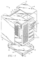
- FIG. 1 shows a rugged computer housing, i.e. a computer housing for protecting electronic components against shock and vibration, generally designated with the reference numeral 12.
- the housing 12 includes a base assembly 14, a chassis assembly 16, a midplane 18 and a side cover assembly 70 having a pair of side covers 20.
- the midplane 18 divides the computer housing 12 into a mainboard section 38 and a chassis section 40.
- the base assembly 14 includes a top face 22, a bottom face 24 and a plurality of casters 26.
- the casters 26 attach to the bottom face 24 to enable the computer housing 12 to roll.
- the top face 22 and the bottom face 24 mate to form a box beam 28.
- the box beam 28 includes reinforcing members 30 which define a portion of the box beam 28 and extend with the box beam 28 to provide rigidity to the base.
- the casters 26 attach to the bottom face 24, under the box beam 28.
- the box beam 28 reinforces the computer housing 12 to support the casters 26.
- the box beam 28 enables the computer housing 12 to resist vibrations due to impact. Reinforcing the computer housing 12 with the box beam 28 also enables the base assembly 14 and the computer housing 12 to resist deformation, to protect the various electronic components within the computer housing 12.
- Excessive computer housing 12 weight may add stress to the connection between the casters 26 and the base and may increase the likelihood of deforming the base and the computer housing 12.
- the box beam minimizes computer housing 12 weight by providing structural support above the casters 26, where support is needed.
- the midplane 18 extends outward from the base assembly 14 to separate the computer housing 12 in to at least two sections.
- the midplane 18 defines a chassis section 40 and a mainboard section 38.
- the midplane 18 cooperates with the base assembly 14 to add rigidity to the housing 12 and to inhibit deformation of the housing 12 due to shock and vibration.
- the midplane 18 isolates the chassis section from the mainboard section. Components, such as disk drives, held in the chassis section 40 are thus isolated from the mainboard section 38. Isolation of components inhibits damage to mainboard section 38 components by chassis assembly 16 components due to vibration.
- the chassis section 40 includes a chassis assembly 16.
- the chassis assembly 16 is isolated as a unit from the remainder of the housing 12 to filter shock and vibration between the chassis assembly 16 and the remainder of the housing 12.
- the chassis assembly 16 includes multiple memory storage device units including a removable storage device module and multiple hard disk drives.
- the removable memory storage device module includes optical disk drives. It can be appreciated, however, that any of a number of memory storage devices may be used.
- the housing 12 has opposing sides with side openings 23.
- the side cover assembly 70 includes a pair of side covers 20 which removeably cover opposing sides and cover the side openings 23 of the computer housing 12.
- the side covers 20 are formed, in part, from molded plastic to resist vibrations. The plastic material causes the side covers to be lightweight and easily removable to enable access to the electrical components by a technician, for example.
- Both side covers 20 have a generally "L" shaped cross-section. Each side cover 20 has a top portion. The top portion of each side cover 20 rests on the computer housing 12 to support weight including accessories, or even a seated person.
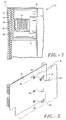
- FIG. 2 shows the mainboard section 38.
- the mainboard section 38 houses electronic components including a mainboard 42, at least one processor unit 44, and multiple cards 46.
- the mainboard 42 includes card slots 48, memory slots 50 and processor unit slots 52 for receiving cards 46, memory modules and the processor unit 44, respectively.
- the processor unit 44 and the cards 46 extend perpendicularly from the mainboard 42 so that when the side covers 20 attach to the housing 12, the side covers press against the processor unit 44 and the cards 46 to internally support the computer housing 12 (FIG 1).
- the cards 46 are rectangular, having four sides.
- the mainboard section 38 has a rear 54 and a retainer 56.
- the cards 46 are held on one side by the rear 54 of the housing 12, on another side by the card slot 48 and on a third side by a retainer 56.
- FIG. 3 shows an embodiment of the midplane 18.
- the midplane 18 includes extensions 58 for mounting the midplane 18 into the base (FIG 1).
- the midplane 18 also includes several mainboard mounts 60 and a cross-rib 62.
- the extensions insert into the base assembly 14 (FIG 1) to hold the midplane 18.
- the midplane 18 adds rigidity to the housing 12 and isolates the chassis section 40 from the mainboard section 38.
- the cross rib 62 is stamped into the midplane 18 and includes contours which inhibit flexion of the midplane 18. Inhibiting flexion of the midplane 18 reduces flexion of the computer housing 12, the mainboard and the other electronic components. This makes the computer housing 12 more rugged in the face of shock and vibration. Increased ruggedness of the housing 12 makes the computer system and electronic components more reliable.
- FIG. 4 shows a mainboard mount 60.
- the mainboard mount 60 includes two fingers 64 which are formed integral with the midplane 18.
- the fingers 64 are separated, and angled towards each other. The separated and angled configuration of the fingers 64 enables the fingers 64 to grip a resilient spacer mount 66.
- the resilient spacer mount 66 is threaded to screw tightly to a mainboard and attach a mainboard to the midplane 18 (FIG 3).
- the resilient spacer mount 66 dampens shock and vibration between the mainboard and the midplane 18.
- FIG. 5 shows several resilient spacer mounts 66 affixed to the mainboard 42.
- the resilient spacer mounts 66 coincide with the mainboard mounts 60 on the midplane 18. Accordingly, the mainboard 42 slides in the direction of the arrows to mate the resilient spacer mounts into the mainboard mounts. This mating arrangement between the spacer mounts 66 and the mainboard 42 holds the mainboard and dampens vibration and shock.
- FIG. 6 shows an exploded view of an embodiment of the side cover assembly, generally designated with the reference numeral 70.
- the side cover assembly 70 is a composite, being formed from a number of integrated elements.
- the composite side cover assembly 70 includes an outer cover 72 having a periphery, a gasket 76 attached within the periphery, an inner member 78 and a pad 80.
- the inner member 78 attaches to the outer cover 72 and compresses the gasket 76 between the outer cover 72 and the inner member 78.
- the inner member 78 is rigid to stiffen the side cover assembly 70.
- the gasket 76 dampens vibrations between the inner member 78 and the outer cover 72.
- the pad 80 dampens vibrations between the side cover assembly 70 and the electronic components including cards 42 and the processor unit 44 (FIG. 2).
- the outer cover 72, the gasket 76, the inner member 78 and the pad 80 function as a single unit (compositely) to encase the housing 12. Encasement of the housing 12 creates an outer shell which inhibits flexion of the housing 12 when the side cover assembly attaches to the computer housing 12.
- the side cover assembly 70 in addition to encasing the housing 12, also provides internal support to the housing 12 (FIG. 1). Internal support results when the side cover assembly 70 presses against the main board 42 to hold the mainboard 42, the cards 46 and the processor unit 44 and protect them against shock and vibration. Encasement and internal support provided by the side cover assembly 70 provides rigidity to the computer housing 12.
- the inner member 78 is fabricated from steel sheet metal to shield electromagnetic energy.
- the inner member also stiffens the side cover.
- the gasket 76 is fabricated in four pieces from sponge urethane rubber to enable the side cover assembly 70 to press fit against with the computer housing 12 side openings and thereby enable the composite side cover assembly structurally to reinforce the housing 12.
- the pad 80 attaches to the inner member 78.
- the pad 80 is fabricated from resilient foam and includes a contoured portion 82.
- the contoured portion 82 of the pad 80 is rectangular shape and coincides with the location of the processor unit 44 (FIG. 2) when the side cover assembly covers the computer housing 12. Accordingly, the contour of the pad presses against the processor unit to restrain the processor unit and to secure the side cover assembly against the housing 12. Restraining the processor unit 44 inhibits communication of vibration and shock to the processor. Securing the side cover assembly inhibits flexion of the housing 12.
- contoured portion 82 of the foam pad 80 is designed having a rectangular shape to press against the processor assembly 44, it can be appreciated that the contoured portion can be specifically designed to press against any of a variety of electronic components including memory chips, daughter boards and cards.
- FIG. 7 is a side view of a portion of the housing 12 where the side cover assembly 70 presses against the processor assembly 44 and a card 46.
- the outer cover 72 presses against the gasket 76, which presses against the inner member 78 which, in turn, presses against the foam pad 80, which presses against electronic components including the processor unit 44 and the card 46, which press into the mainboard 42, which presses against the midplane 18.
- the side cover assembly 70 compresses the foam pad 80 against the cards 46 to support the mainboard 42 and to enable the cards 46 and the mainboard 42 to internally support the computer housing 12. Holding the cards 46 with the pad 80 enables the mainboard 42, the side cover assembly 70 and the midplane 18 to function as a single unit.
- the side cover assembly, the mainboard 42 and the midplane 18 function as a composite structure.
- the contoured portion 82 of the foam pad 80 presses with relatively greater pressure against the processor assembly 44 than the relatively fragile card 46. This pressure is adjusted by the shape of the contoured portion 82.
- outer cover 72 The cooperation of the structure: outer cover 72, the gasket 76, the inner member, the foam pad, the electronic components including the processor unit 44 and the card 46, the mainboard 42, and the midplane 18, provides internal rigidity to the computer housing to inhibit flexion of the computer housing 12. This cooperation of structure also dampens vibrations while inhibiting movement of the various electronic components. This cooperation of structure also strengthens the side cover assembly 70 so that the computer housing 12 supports an increased amount of weight.
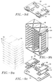
- FIG. 8 is a perspective view of the removable storage media unit 86.
- the unit 86 includes a pair of optical drives 88 and a floppy drive 90.
- the unit 86 mounts on resilient spacer mounts 92 to isolate the removable storage media unit from the remainder of the housing 12. Isolation of the removable storage media unit dampens vibrations to reduce the risk of damage to the optical drive 88 and floppy drive 90 during impact and vibrations.
- FIG. 9a shows multiple memory storage devices 94 which removeably insert into the chassis assembly 16.
- the memory storage devices 94 may be hard disk drives or virtually any other type of removable memory storage device.
- FIG. 9b, 9c and 9d show an exploded view of the disk chassis assembly 16.
- the chassis assembly 16 includes a top 96, a bottom 98 and a suspension mount.
- the suspension mount includes a pair of isolation mounts 100.
- the isolation mounts 100 attach to both the top 96 and to the bottom 98.
- FIG 9c and FIG 9d show top and bottom isolation mounts 100, respectively.
- the isolation mounts 100 each include a base plate 102, a pair of loose bar mounts 104, a capture bracket 106 and a plurality of high mass load snubbers 108.
- the base plate 102 supports the pair of loose bar mounts 104 in parallel.
- the capture bracket 106 holds the loose bar mounts 104 on the base plate and the snubbers 108 support the chassis independently of the loose bar mounts 104.
- the capture bracket 106 removeably attaches to the base plate 102 to secure the loose bar mounts 104 between the base plate 102 and the capture bracket 106.
- Each capture bracket has one side with tabs. The tabs insert into the base plate so that each capture bracket folds over the isolation mount.
- the top 96 and bottom 98 of the chassis assembly 16 are formed of sheet metal having a cross-rib to stiffen the top and bottom of the chassis assembly to provide rigidity to the chassis assembly 16 and to dampen vibrations.
- Each capture bracket 106 includes an opening which exposes a portion 110 of the loose bar mount 104 serving as a spacer.
- the exposed portion 110 contacts the chassis assembly 16.
- the loose bar mounts 104 are resilient and dampen vibrations between the computer housing and the chassis assembly 16.
- the snubbers 108 support the chassis assembly 16 independently of the loose bar mounts 104 and protect the disk chassis against severe impact.
- the chassis assembly 16 has lateral sides 112. Further snubbers 109 attach to the lateral sides to protect the memory storage devices 94 against shock due to impact.
- Each spacer 110 has a generally trapezoidal cross section so that the spacers are compressible under a variety of loading forces.
- FIG. 9d shows the top isolation mount 100.
- the top isolation mount 100 attaches via the loose bar mounts 104 the top 96 of the chassis assembly 16.
- the loose bar mounts 104 suspend the chassis assembly 16 within the housing 12 so that vibrations from the memory storage devices 94 do not pervade the housing 12.
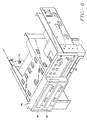
- FIG. 10 shows an exploded view of the base assembly 14, including the top face 22, the bottom face 24 and the reinforcing members 30.
- the base assembly 14 includes two parallel reinforcing members 30 welded to the bottom face 24.
- the reinforcing members 30 have an "I" beam cross-section.
- the box beam 28 has an inner periphery 34.
- the reinforcing members 30 align with the inner periphery 34. Alignment with the inner periphery of the box beam 28 enables the reinforcing members 30 to define a portion of the box beam 28 and provide rigidity to the base assembly 14.
- the reinforcing members 30 align centrally within the box beam 28 and the casters attach directly to the reinforcing members 30.
- the base assembly 14 supports the housing 12 so that the housing 12 can roll on casters 26 without significantly flexing. Significant flexion of the base assembly 14 and of the housing 12 can cause a mainboard, and/or other electronic components of a computer system to fail. Flexion of the base assembly 14 may also inhibit operation of the casters 26.
- the box beam 28 of the base assembly reinforces the base assembly so that the casters 26 may mount directly to the box beam 28.
- the box beam 28 may be modified in a number of ways which will operate to reinforce the base assembly 14 for the casters 26.
- the box beam functions not only to reinforce the base assembly 14, but also to diffuse forces encountered by the casters 26.
- Various box beam configurations will accomplish these goals.
- the box beam 28 may be modified or varied to have a trapezoidal, or circular cross-section, instead of the rectangular cross section.
- the chassis assembly 16 is designed primarily to hold rotating and vibrating hard disk drives.
- the isolation mount 100 dampens shock and vibrations between the base assembly and the chassis assembly 16. These vibrations are normally caused by the disk drives. It can be appreciated, however, that the isolation mount 100 can also protect the disk drives from various frequency vibrations such as those that result when, for example, the casters 26 hit a door jamb. Isolating the hard disk drives protects the electronic components in the mainboard side of the housing.
- the midplane 18 isolates the mainboard section from the chassis assembly 16 and the midplane internally supports the housing in a variety of ways.
- One way in which the midplane 18 functions is by cooperating with the side cover assembly as a composite structure.
- the side cover assembly 70 encloses the chassis assembly and the mainboard section to externally support the housing.
- the side cover assembly 70 also cooperates with the midplane to internally support the housing.
- the side cover assembly 70 closes over the housing 12 and presses the electronic components against the midplane 18. Accordingly, the side cover assembly 70, the electronic components and the midplane 18 function as a single structure internally to support the housing 12.
- the housing 12 has a side opening for receiving the side cover assembly 70.
- the gasket 76 of the side cover assembly 70 is fabricated from sponge urethane rubber and the rigid inner member 78 is fabricated from sheet metal.
- the rigid inner member 78 provides rigidity to the side cover assembly 70 to enable the side cover assembly 70 to press fit against the housing 12 and cover the side opening.
- the housing can be particularly adapted in various shapes and configurations to house components other than those shown herein.
- the cooperation between elements which create and outer shell and inner support to the housing can manifest themselves in a wide variety of configurations.
Landscapes
- Engineering & Computer Science (AREA)
- Theoretical Computer Science (AREA)
- Computer Hardware Design (AREA)
- General Engineering & Computer Science (AREA)
- Power Engineering (AREA)
- Human Computer Interaction (AREA)
- Physics & Mathematics (AREA)
- General Physics & Mathematics (AREA)
- Casings For Electric Apparatus (AREA)
- Mounting Of Printed Circuit Boards And The Like (AREA)
Claims (29)
- Boítier (12) destiné à protéger des composants électroniques, le boítier comprenant :un assemblage (14) formant socle destiné à soutenir le boítier ;un assemblage (16) formant châssis monté sur l'assemblage formant socle, dans lequel l'assemblage formant châssis est fixé à l'assemblage formant socle par un support d'isolation destiné à amortir les chocs et vibrations entre l'assemblage formant socle et l'assemblage formant châssis ;un plan médian (18) fixé à l'assemblage formant socle et s'étendant vers l'extérieur de celui-ci pour séparer le boítier en une section (38) destinée à loger une carte-mère et une section (40) qui loge l'assemblage formant châssis, le plan médian étant conçu pour soutenir le boítier de façon interne ; etun assemblage (70) formant enveloppe latérale monté sur l'assemblage formant socle et conçu pour pousser des composants électroniques contre le plan médian pour soutenir le boítier de manière interne.
- Boítier selon la revendication (1) dans lequel l'assemblage formant socle comprend des roulettes (26), une face supérieure (22) et une face inférieure (24), lesquelles faces forment un caisson (28).
- Boítier selon la revendication 1 ou 2, dans lequel le plan médian (18) est structuré pour ajouter de la rigidité au boítier.
- Boítier selon la revendication 1, 2 ou 3, comprenant en outre une carte-mère (42) fixée au plan médian et logée dans la section (38) de carte-mère du boítier, la carte-mère incluant un module (44) de processeur et des fentes (48) pour carte, destinées à recevoir des cartes.
- Boítier selon la revendication 4, dans lequel l'assemblage formant enveloppe latérale renferme l'assemblage formant châssis et le plan médian, et dans lequel l'assemblage formant enveloppe latérale est conçu pour pousser contre la carte-mère qui à son tour pousse contre le plan médian.
- Boítier selon la revendication 4 ou 5, dans lequel la carte-mère, l'enveloppe latérale et le plan médian coopèrent pour renforcer le boítier.
- Boítier selon l'une quelconque des revendications précédentes, dans lequel l'assemblage formant enveloppe latérale renferme l'assemblage formant châssis et la section de carte-mère.
- Boítier selon l'une quelconque des revendications précédentes, dans lequel l'assemblage formant enveloppe latérale comprend un moyen formant joint d'enveloppe extérieure et un élément interne rigide qui coopèrent pour soutenir le boítier de manière externe.
- Boítier selon la revendication 8, dans lequel le boítier comporte une ouverture latérale destinée à recevoir l'assemblage formant enveloppe latérale, dans lequel le moyen formant joint comprend un joint fabriqué à partir d'un caoutchouc d'uréthane spongieux et dans lequel l'élément interne rigide est fabriqué à partir d'un métal en feuille, l'élément interne rigide donnant de la rigidité à l'assemblage formant enveloppe latérale pour permettre à l'enveloppe latérale de se monter à force contre le boítier et de recouvrir l'ouverture latérale.
- Boítier selon la revendication 8, dans lequel l'assemblage formant enveloppe latérale comprend un coussin fixé à l'élément interne, dans lequel la section de carte-mère comprend une carte-mère avec des cartes et un module de processeur, dans lequel l'enveloppe externe applique de façon étanche le moyen formant joint contre le boítier et presse le coussin contre au moins une partie de l'assemblage formant carte-mère.
- Boítier selon la revendication 10, dans lequel le coussin est conçu pour pousser contre le module de processeur.
- Boítier selon la revendication 11, dans lequel le coussin comprend une partie profilée par laquelle le coussin pousse contre le module de processeur.
- Boítier selon la revendication 10, 11 ou 12, dans lequel le coussin est conçu pour pousser contre les cartes pour interdire la vibration des cartes et pour pousser les cartes et la carte-mère dans le plan médian de façon que les cartes et la carte-mère ajoutent un soutien structurel au boítier.
- Boítier d'ordinateur selon l'une quelconque des revendications 1 à 7, dans lequel l'assemblage formant enveloppe latérale comprend une enveloppe externe, un joint, un élément interne et un coussin, l'élément interne servant à raidir l'assemblage formant enveloppe latérale, le joint servant à amortir des vibrations entre l'assemblage formant enveloppe latérale et le boítier, l'enveloppe externe servant à tenir le joint et l'élément interne, et le coussin servant à pousser contre au moins une partie de l'assemblage formant carte-mère pour maintenir la carte-mère contre le plan médian.
- Boítier selon la revendication 14, dans lequel le coussin comprend une partie profilée par l'intermédiaire de laquelle le coussin pousse contre le module de processeur.
- Boítier selon la revendication 14 ou 15, dans lequel la carte-mère comprend des cartes, le coussin étant conçu pour pousser contre les cartes pour interdire la vibration des cartes et pour pousser les cartes et la carte-mère dans le plan médian.
- Boítier selon l'une quelconque des revendications précédentes, dans lequel l'assemblage formant châssis comprend un sommet et une base, et dans lequel le support d'isolation se fixe à la fois au sommet et à la base.
- Boítier selon l'une quelconque des revendications précédentes, dans lequel le support d'isolation suspend l'assemblage formant châssis.
- Boítier selon l'une quelconque des revendications précédentes, dans lequel le support d'isolation comprend une plaque de base, une paire de supports à barre libre, une console d'ancrage et une pluralité d'amortisseurs, dans lequel la plaque de base soutient la paire de supports à barre libre sensiblement en parallèle, dans lequel la console d'ancrage maintient les supports à barre libre sur la plaque de base, et dans lequel les amortisseurs soutiennent le châssis indépendamment des supports à barre libre.
- Boítier selon la revendication 19, dans lequel les amortisseurs sont des amortisseurs à charge de masse élevée.
- Boítier selon l'une quelconque des revendications précédentes, dans lequel le plan médian comprend une nervure en croix et dans lequel la nervure en croix est emboutie dans le plan médian pour renforcer le plan médian.
- Boítier selon l'une quelconque des revendications précédentes, dans lequel le boítier est un boítier d'ordinateur.
- Boítier selon l'une quelconque des revendications précédentes, dans lequel l'assemblage formant châssis comporte au moins un tiroir, ledit au moins un tiroir étant destiné à contenir un dispositif de stockage en mémoire.
- Boítier selon l'une quelconque des revendications 1 à 17, comprenant en outre un module (86) destiné à protéger des composants électroniques contre des chocs et vibrations, le module comprenant :un assemblage (16) formant châssis comportant un sommet (96) et une base (98) ;un premier support d'isolation (100) fixé au sommet de l'assemblage formant châssis de façon à suspendre l'assemblage formant châssis ; etun second support d'isolation (100) fixé à la base de façon à soutenir l'assemblage formant châssis, le second support d'isolation incluant un écarteur élastique (110) et une console (106) d'ancrage, la console d'ancrage renfermant au moins une partie de l'écarteur élastique pour permettre à l'écarteur élastique de flotter à l'intérieur de la console d'ancrage.
- Boítier selon la revendication 24, dans lequel le support d'isolation comprend une paire de supports (104) à barre libre, chaque support à barre incluant une barre possédant deux extrémités, chaque extrémité incluant un écarteur élastique et chaque écarteur ayant une section globalement trapézoïdale de façon que les écarteurs soient compressibles sous toute une variété de forces de charge.
- Boítier selon la revendication 24 ou 25, dans lequel chaque console d'ancrage possède un côté avec des pattes, les pattes étant introduites dans la plaque de base de façon que chaque console d'ancrage se rabatte sur le support d'isolation.
- Boítier selon l'une quelconque des revendications 24, 25 ou 26, dans lequel le sommet et la base du châssis sont faits de métal en feuille comportant une nervure en croix pour raidir le sommet et la base du châssis pour donner de la rigidité au châssis et pour amortir les vibrations.
- Boítier selon l'une quelconque des revendications 24 à 27, dans lequel le support de suspension comprend une paire de supports d'isolation, chacun avec un écarteur élastique et une console d'ancrage, chaque écarteur s'étirant sous traction pour suspendre le châssis.
- Boítier selon l'une quelconque des revendications 24 à 28, dans lequel l'assemblage (16) formant châssis possède des côtés latéraux (112) s'étendant entre le sommet et la base de l'assemblage formant châssis et comprend en outre des amortisseurs (109) fixés aux côtés latéraux pour protéger, contre un choc dû à un impact, les composants électroniques logés dans le module.
Applications Claiming Priority (2)
| Application Number | Priority Date | Filing Date | Title |
|---|---|---|---|
| US892929 | 1997-07-15 | ||
| US08/892,929 US5867369A (en) | 1997-07-15 | 1997-07-15 | Rugged computer housing |
Publications (2)
| Publication Number | Publication Date |
|---|---|
| EP0892336A1 EP0892336A1 (fr) | 1999-01-20 |
| EP0892336B1 true EP0892336B1 (fr) | 2002-04-03 |
Family
ID=25400728
Family Applications (1)
| Application Number | Title | Priority Date | Filing Date |
|---|---|---|---|
| EP98305597A Expired - Lifetime EP0892336B1 (fr) | 1997-07-15 | 1998-07-14 | Boítier pour ordinateur |
Country Status (4)
| Country | Link |
|---|---|
| US (1) | US5867369A (fr) |
| EP (1) | EP0892336B1 (fr) |
| JP (1) | JPH11110080A (fr) |
| DE (1) | DE69804548T2 (fr) |
Cited By (1)
| Publication number | Priority date | Publication date | Assignee | Title |
|---|---|---|---|---|
| CN102156508A (zh) * | 2010-02-11 | 2011-08-17 | 陈亮合 | 直立式电脑主机 |
Families Citing this family (54)
| Publication number | Priority date | Publication date | Assignee | Title |
|---|---|---|---|---|
| NO986129L (no) * | 1998-12-23 | 2000-06-26 | Cit Alcatel | Beskyttet modulært hus for substrat |
| US6129429A (en) * | 1999-02-12 | 2000-10-10 | Compaq Computer Corporation | Rack serviceable computer chassis assembly |
| US6038126A (en) * | 1999-04-21 | 2000-03-14 | Shin Jiuh Corp. | Electrical power supply assembly |
| US6885550B1 (en) | 1999-08-26 | 2005-04-26 | Axxion Group Corporation | Screw less clip mounted computer drive |
| US6619766B1 (en) | 1999-10-12 | 2003-09-16 | Gateway, Inc. | Device mounting and retention assembly |
| US6293636B1 (en) | 1999-12-30 | 2001-09-25 | Gateway, Inc. | Device retention assembly |
| US6367748B1 (en) * | 2000-02-12 | 2002-04-09 | Solvisions Technologies Int'l | Apparatus for providing desktop mobility for desktop electronic devices |
| US6456489B1 (en) | 2000-05-25 | 2002-09-24 | Gateway, Inc. | Device retention apparatus |
| US6454250B1 (en) | 2000-10-17 | 2002-09-24 | Spx Corporation | Shock absorbing apparatus |
| US6795310B2 (en) * | 2000-12-28 | 2004-09-21 | Intel Corporation | Enhanced space utilization for enclosures enclosing heat management components |
| US6693371B2 (en) * | 2001-02-06 | 2004-02-17 | American Power Corporation | Integrated uninterruptible power supply enclosure |
| RU2329529C2 (ru) * | 2001-07-25 | 2008-07-20 | Интегрэф Хадвеа Текнолоджис Кампэни | Компьютерная консоль оператора и устройство воспроизведения изображений на экране (варианты) |
| USD481388S1 (en) | 2002-04-24 | 2003-10-28 | Kabushiki Kaisha Toshiba | Operation controller for electronic computers |
| USD481385S1 (en) | 2002-04-24 | 2003-10-28 | Kabushiki Kaisha Toshiba | Electronic computer |
| USD484508S1 (en) | 2002-11-27 | 2003-12-30 | International Business Machines Corporation | Server blade enclosure base |
| US7164581B2 (en) * | 2004-06-21 | 2007-01-16 | Computer Network Technology Corp. | Modular chassis divided along a midplane and cooling system therefor |
| US7663878B2 (en) * | 2006-03-23 | 2010-02-16 | Harris Kent Swan | Modular protective housing with peripherals for a handheld communications device |
| US20070241452A1 (en) * | 2006-04-12 | 2007-10-18 | Inventec Corporation | Electronic device with a movable mechanism |
| US7566104B2 (en) * | 2006-05-08 | 2009-07-28 | Lian Li Industrial Co., Ltd. | Bi-directional side emplacing computer casing |
| USD626955S1 (en) * | 2009-03-02 | 2010-11-09 | Verizon Patent And Licensing Inc. | Optical network terminal |
| EP2410398B1 (fr) * | 2010-07-20 | 2013-07-31 | Liang-Ho Cheng | Système informatique de tour |
| US8988895B2 (en) * | 2011-08-23 | 2015-03-24 | Tessera, Inc. | Interconnection elements with encased interconnects |
| USD673959S1 (en) * | 2011-10-13 | 2013-01-08 | Hewlett-Packard Development Company, L.P. | Cover plate for a computing device |
| USD673160S1 (en) * | 2011-10-13 | 2012-12-25 | Hewlett-Packard Development Company, L.P. | Cover plate for a computing device |
| USD673161S1 (en) * | 2011-10-13 | 2012-12-25 | Hewlett-Packard Development Company, L.P. | Perforation pattern for a cover plate for a computing device |
| USD672354S1 (en) * | 2011-10-13 | 2012-12-11 | Hewlett-Packard Development Company, L.P. | Cover plate for a computing device |
| WO2013119243A1 (fr) | 2012-02-09 | 2013-08-15 | Hewlett-Packard Development Company, L.P. | Système de dissipation thermique |
| EP2826347B1 (fr) | 2012-03-12 | 2017-10-25 | Hewlett-Packard Enterprise Development LP | Refroidissement à régulation de température de liquide |
| USD698074S1 (en) | 2012-04-17 | 2014-01-21 | Ip Holdings, Llc | External ballast frame |
| EP2901828A4 (fr) | 2012-09-28 | 2016-06-01 | Hewlett Packard Development Co | Ensemble de refroidissement |
| EP2915417B1 (fr) | 2012-10-31 | 2017-11-29 | Hewlett-Packard Enterprise Development LP | Système de bâti modulaire |
| USD707224S1 (en) * | 2012-12-21 | 2014-06-17 | Zalman Tech Co., Ltd. | Computer case |
| USD706273S1 (en) * | 2013-01-04 | 2014-06-03 | Hewlett-Packard Development Company, L.P. | Bezel for a computing device |
| USD705784S1 (en) * | 2013-01-04 | 2014-05-27 | Hewlett-Packard Development Company, L.P. | Bezel for a computing device |
| USD707225S1 (en) * | 2013-01-22 | 2014-06-17 | Zalman Tech Co., Ltd. | Computer case |
| FR3001603B1 (fr) * | 2013-01-29 | 2015-03-20 | Airbus Operations Sas | Carte electronique pour equipement avionique comprenant des moyens amortisseurs de vibrations entre son cadre de renfort et ses moyens de maintien |
| WO2014120182A1 (fr) | 2013-01-31 | 2014-08-07 | Hewlett-Packard Development Company, L.P. | Refroidissement de liquide |
| ITRM20130540A1 (it) * | 2013-10-04 | 2015-04-05 | Ecm S P A | Posto periferico di controllo di enti di piazzale ferroviario e metodo di installazione di detto posto periferico |
| USD740282S1 (en) * | 2013-10-22 | 2015-10-06 | Western Digital Technologies, Inc. | Storage device |
| USD757344S1 (en) * | 2014-08-26 | 2016-05-24 | Ip Holdings, Llc | Ballast housing |
| USD761481S1 (en) * | 2014-08-26 | 2016-07-12 | Ip Holdings, Llc | Ballast housing |
| USD760222S1 (en) | 2014-10-29 | 2016-06-28 | Western Digital Technologies, Inc. | Storage device |
| USD780691S1 (en) | 2015-05-20 | 2017-03-07 | Ip Holdings, Llc | Remote ballast |
| CN104951023A (zh) * | 2015-07-15 | 2015-09-30 | 王学香 | 一种加固计算机 |
| US20190094911A1 (en) * | 2017-09-25 | 2019-03-28 | The United State Of America As Represented By The Secretary Of The Navy | System and Method for Ruggedized Remote Communication |
| USD855238S1 (en) | 2017-10-27 | 2019-07-30 | Hgci, Inc. | Ballast |
| USD871654S1 (en) | 2017-10-30 | 2019-12-31 | Hgci, Inc. | Light fixture |
| USD895607S1 (en) | 2019-05-31 | 2020-09-08 | Apple Inc. | Electronic device |
| USD942441S1 (en) * | 2019-06-01 | 2022-02-01 | Apple Inc. | Electronic device |
| KR102565678B1 (ko) * | 2020-10-26 | 2023-08-14 | (주)케이티엔에프 | 현장 온도를 감내하기 위한 엣지컴퓨팅시스템 |
| KR102565749B1 (ko) * | 2020-10-26 | 2023-08-16 | (주)케이티엔에프 | 러기드 환경을 위한 엣지컴퓨팅시스템 |
| WO2022104416A1 (fr) * | 2020-11-17 | 2022-05-27 | Tritium Holdings Pty Ltd | Ensemble électronique modulaire |
| CN112739094B (zh) * | 2020-12-22 | 2022-03-22 | 安徽飞凯电子技术有限公司 | 一种服务器用智能降噪机柜 |
| JP7711487B2 (ja) * | 2021-08-23 | 2025-07-23 | 富士フイルムビジネスイノベーション株式会社 | キャスタ保護構造及びこれを用いた筐体構造、物品 |
Family Cites Families (11)
| Publication number | Priority date | Publication date | Assignee | Title |
|---|---|---|---|---|
| US4728160A (en) * | 1986-10-22 | 1988-03-01 | Digital Equipment Corporation | Cabinet for a computer assembly |
| US4937806A (en) * | 1988-02-12 | 1990-06-26 | Mdb Systems, Inc. | Shock-isolated portable mass data storage device |
| US5040161A (en) * | 1989-04-27 | 1991-08-13 | Hewlett-Packard Company | Sheet metal housing with precision mounting references |
| US5031070A (en) * | 1990-06-05 | 1991-07-09 | Kai Hsu | Structure of computer housing |
| US5271152A (en) * | 1990-12-07 | 1993-12-21 | Compuadd Corporation | Process for making a computer tower chassis using modules |
| US5162976A (en) * | 1991-06-27 | 1992-11-10 | Compaq Computer Corporation | Double housing wall security locking apparatus for a computer |
| DE9108650U1 (de) * | 1991-07-13 | 1992-11-12 | Tappert, Karl-Heinz, 4018 Langenfeld | Lagerung für ein Festplattenlaufwerk oder dgl. |
| US6640235B1 (en) * | 1992-08-20 | 2003-10-28 | Intel Corporation | Expandable mass disk drive storage system |
| US5349132A (en) * | 1993-02-08 | 1994-09-20 | Apple Computer, Inc. | Methods and apparatus for modular computer construction |
| US5590023A (en) * | 1995-07-26 | 1996-12-31 | Dell Usa Lp | Computer apparatus for suspension of computer expansion cards |
| US5680295A (en) * | 1995-11-13 | 1997-10-21 | Ast Research, Inc. | Ventilated backplane for mounting disk drives in computer systems |
-
1997
- 1997-07-15 US US08/892,929 patent/US5867369A/en not_active Expired - Lifetime
-
1998
- 1998-07-14 DE DE69804548T patent/DE69804548T2/de not_active Expired - Fee Related
- 1998-07-14 EP EP98305597A patent/EP0892336B1/fr not_active Expired - Lifetime
- 1998-07-15 JP JP10200220A patent/JPH11110080A/ja active Pending
Cited By (1)
| Publication number | Priority date | Publication date | Assignee | Title |
|---|---|---|---|---|
| CN102156508A (zh) * | 2010-02-11 | 2011-08-17 | 陈亮合 | 直立式电脑主机 |
Also Published As
| Publication number | Publication date |
|---|---|
| DE69804548D1 (de) | 2002-05-08 |
| US5867369A (en) | 1999-02-02 |
| DE69804548T2 (de) | 2002-10-31 |
| EP0892336A1 (fr) | 1999-01-20 |
| JPH11110080A (ja) | 1999-04-23 |
Similar Documents
| Publication | Publication Date | Title |
|---|---|---|
| EP0892336B1 (fr) | Boítier pour ordinateur | |
| US6498722B1 (en) | Disk drive isolation mount | |
| US5209356A (en) | Acoustic rack | |
| US6049449A (en) | Computer with modular removable card cage | |
| US6094342A (en) | Disk drive jacket | |
| US5004207A (en) | Shock mounting structure and magnetic disk apparatus | |
| US6585534B2 (en) | Retention mechanism for an electrical assembly | |
| US7420798B2 (en) | Portable microcomputer and display unit | |
| US6320760B1 (en) | Multiple PCI card support | |
| US6606242B2 (en) | Universal adapter bracket for mounting electronic devices | |
| US20050001037A1 (en) | Terminal design with shock isolation assembly | |
| US6700791B1 (en) | Computer expansion card retainer assembly | |
| KR100267163B1 (ko) | 래크에 설치가능한 섀시 인클로우져 | |
| US6652314B2 (en) | Components for a computer sub-assembly | |
| US20030035281A1 (en) | Shock absorber module | |
| US20080013273A1 (en) | Computer chassis having a tuning gasket | |
| US6233147B1 (en) | Apparatus for securing a component in a computer chassis | |
| US5221811A (en) | Shock mounting housing apparatus | |
| JPH08223942A (ja) | インバータの寿命部品の着脱装置 | |
| JPH06236669A (ja) | 記憶装置の衝撃緩衝部材 | |
| CN100511093C (zh) | 用于在计算机系统中安装部件的系统和方法 | |
| US5261648A (en) | Computer isolating device | |
| JPH03110329A (ja) | 空気調和機の圧縮機支持装置 | |
| CN220962794U (zh) | 一种硬盘防震装置和可插拔硬盘套件 | |
| JPH08123927A (ja) | ハードディスク装置搭載icカードおよびハードディスク装置搭載回路基板 |
Legal Events
| Date | Code | Title | Description |
|---|---|---|---|
| PUAI | Public reference made under article 153(3) epc to a published international application that has entered the european phase |
Free format text: ORIGINAL CODE: 0009012 |
|
| AK | Designated contracting states |
Kind code of ref document: A1 Designated state(s): DE FR GB IT NL SE |
|
| AX | Request for extension of the european patent |
Free format text: AL;LT;LV;MK;RO;SI |
|
| 17P | Request for examination filed |
Effective date: 19990629 |
|
| AKX | Designation fees paid |
Free format text: DE FR GB IT NL SE |
|
| 17Q | First examination report despatched |
Effective date: 19990831 |
|
| GRAG | Despatch of communication of intention to grant |
Free format text: ORIGINAL CODE: EPIDOS AGRA |
|
| GRAG | Despatch of communication of intention to grant |
Free format text: ORIGINAL CODE: EPIDOS AGRA |
|
| GRAG | Despatch of communication of intention to grant |
Free format text: ORIGINAL CODE: EPIDOS AGRA |
|
| GRAH | Despatch of communication of intention to grant a patent |
Free format text: ORIGINAL CODE: EPIDOS IGRA |
|
| GRAH | Despatch of communication of intention to grant a patent |
Free format text: ORIGINAL CODE: EPIDOS IGRA |
|
| REG | Reference to a national code |
Ref country code: GB Ref legal event code: IF02 |
|
| GRAA | (expected) grant |
Free format text: ORIGINAL CODE: 0009210 |
|
| AK | Designated contracting states |
Kind code of ref document: B1 Designated state(s): DE FR GB IT NL SE |
|
| REF | Corresponds to: |
Ref document number: 69804548 Country of ref document: DE Date of ref document: 20020508 |
|
| PGFP | Annual fee paid to national office [announced via postgrant information from national office to epo] |
Ref country code: FR Payment date: 20020710 Year of fee payment: 5 |
|
| PGFP | Annual fee paid to national office [announced via postgrant information from national office to epo] |
Ref country code: GB Payment date: 20020712 Year of fee payment: 5 |
|
| PGFP | Annual fee paid to national office [announced via postgrant information from national office to epo] |
Ref country code: SE Payment date: 20020717 Year of fee payment: 5 |
|
| PGFP | Annual fee paid to national office [announced via postgrant information from national office to epo] |
Ref country code: NL Payment date: 20020731 Year of fee payment: 5 |
|
| PGFP | Annual fee paid to national office [announced via postgrant information from national office to epo] |
Ref country code: DE Payment date: 20020807 Year of fee payment: 5 |
|
| ET | Fr: translation filed | ||
| PLBE | No opposition filed within time limit |
Free format text: ORIGINAL CODE: 0009261 |
|
| STAA | Information on the status of an ep patent application or granted ep patent |
Free format text: STATUS: NO OPPOSITION FILED WITHIN TIME LIMIT |
|
| 26N | No opposition filed |
Effective date: 20030106 |
|
| PG25 | Lapsed in a contracting state [announced via postgrant information from national office to epo] |
Ref country code: GB Free format text: LAPSE BECAUSE OF NON-PAYMENT OF DUE FEES Effective date: 20030714 |
|
| PG25 | Lapsed in a contracting state [announced via postgrant information from national office to epo] |
Ref country code: SE Free format text: LAPSE BECAUSE OF NON-PAYMENT OF DUE FEES Effective date: 20030715 |
|
| PG25 | Lapsed in a contracting state [announced via postgrant information from national office to epo] |
Ref country code: NL Free format text: LAPSE BECAUSE OF NON-PAYMENT OF DUE FEES Effective date: 20040201 |
|
| PG25 | Lapsed in a contracting state [announced via postgrant information from national office to epo] |
Ref country code: DE Free format text: LAPSE BECAUSE OF NON-PAYMENT OF DUE FEES Effective date: 20040203 |
|
| EUG | Se: european patent has lapsed | ||
| GBPC | Gb: european patent ceased through non-payment of renewal fee |
Effective date: 20030714 |
|
| PG25 | Lapsed in a contracting state [announced via postgrant information from national office to epo] |
Ref country code: FR Free format text: LAPSE BECAUSE OF NON-PAYMENT OF DUE FEES Effective date: 20040331 |
|
| NLV4 | Nl: lapsed or anulled due to non-payment of the annual fee |
Effective date: 20040201 |
|
| REG | Reference to a national code |
Ref country code: FR Ref legal event code: ST |
|
| PG25 | Lapsed in a contracting state [announced via postgrant information from national office to epo] |
Ref country code: IT Free format text: LAPSE BECAUSE OF NON-PAYMENT OF DUE FEES Effective date: 20050714 |