EP0892481A1 - Bobine de moteur pour pièce d'horlogerie - Google Patents
Bobine de moteur pour pièce d'horlogerie Download PDFInfo
- Publication number
- EP0892481A1 EP0892481A1 EP97112022A EP97112022A EP0892481A1 EP 0892481 A1 EP0892481 A1 EP 0892481A1 EP 97112022 A EP97112022 A EP 97112022A EP 97112022 A EP97112022 A EP 97112022A EP 0892481 A1 EP0892481 A1 EP 0892481A1
- Authority
- EP
- European Patent Office
- Prior art keywords
- plate
- coil
- wires
- winding
- circuit
- Prior art date
- Legal status (The legal status is an assumption and is not a legal conclusion. Google has not performed a legal analysis and makes no representation as to the accuracy of the status listed.)
- Granted
Links
- 238000004804 winding Methods 0.000 claims abstract description 24
- 210000005069 ears Anatomy 0.000 claims description 5
- 238000000034 method Methods 0.000 claims description 5
- 239000000523 sample Substances 0.000 claims description 4
- 238000005259 measurement Methods 0.000 claims description 2
- 238000012550 audit Methods 0.000 claims 1
- 239000004020 conductor Substances 0.000 claims 1
- 238000003908 quality control method Methods 0.000 claims 1
- 238000010438 heat treatment Methods 0.000 description 3
- 238000005476 soldering Methods 0.000 description 3
- 238000003466 welding Methods 0.000 description 3
- ATJFFYVFTNAWJD-UHFFFAOYSA-N Tin Chemical compound [Sn] ATJFFYVFTNAWJD-UHFFFAOYSA-N 0.000 description 2
- 239000000463 material Substances 0.000 description 2
- 238000000465 moulding Methods 0.000 description 2
- 208000031968 Cadaver Diseases 0.000 description 1
- 238000004873 anchoring Methods 0.000 description 1
- 239000011248 coating agent Substances 0.000 description 1
- 238000000576 coating method Methods 0.000 description 1
- 229940082150 encore Drugs 0.000 description 1
- 238000003780 insertion Methods 0.000 description 1
- 230000037431 insertion Effects 0.000 description 1
- 239000011810 insulating material Substances 0.000 description 1
- 239000012212 insulator Substances 0.000 description 1
- 238000004519 manufacturing process Methods 0.000 description 1
- 210000002445 nipple Anatomy 0.000 description 1
- 238000003825 pressing Methods 0.000 description 1
- 239000010453 quartz Substances 0.000 description 1
- VYPSYNLAJGMNEJ-UHFFFAOYSA-N silicon dioxide Inorganic materials O=[Si]=O VYPSYNLAJGMNEJ-UHFFFAOYSA-N 0.000 description 1
- 229910000679 solder Inorganic materials 0.000 description 1
- 239000002699 waste material Substances 0.000 description 1
Images


Classifications
-
- G—PHYSICS
- G04—HOROLOGY
- G04C—ELECTROMECHANICAL CLOCKS OR WATCHES
- G04C3/00—Electromechanical clocks or watches independent of other time-pieces and in which the movement is maintained by electric means
- G04C3/008—Mounting, assembling of components
-
- H—ELECTRICITY
- H01—ELECTRIC ELEMENTS
- H01F—MAGNETS; INDUCTANCES; TRANSFORMERS; SELECTION OF MATERIALS FOR THEIR MAGNETIC PROPERTIES
- H01F41/00—Apparatus or processes specially adapted for manufacturing or assembling magnets, inductances or transformers; Apparatus or processes specially adapted for manufacturing materials characterised by their magnetic properties
- H01F41/02—Apparatus or processes specially adapted for manufacturing or assembling magnets, inductances or transformers; Apparatus or processes specially adapted for manufacturing materials characterised by their magnetic properties for manufacturing cores, coils, or magnets
- H01F41/04—Apparatus or processes specially adapted for manufacturing or assembling magnets, inductances or transformers; Apparatus or processes specially adapted for manufacturing materials characterised by their magnetic properties for manufacturing cores, coils, or magnets for manufacturing coils
- H01F41/10—Connecting leads to windings
-
- H—ELECTRICITY
- H02—GENERATION; CONVERSION OR DISTRIBUTION OF ELECTRIC POWER
- H02K—DYNAMO-ELECTRIC MACHINES
- H02K11/00—Structural association of dynamo-electric machines with electric components or with devices for shielding, monitoring or protection
- H02K11/30—Structural association with control circuits or drive circuits
- H02K11/33—Drive circuits, e.g. power electronics
-
- H—ELECTRICITY
- H02—GENERATION; CONVERSION OR DISTRIBUTION OF ELECTRIC POWER
- H02K—DYNAMO-ELECTRIC MACHINES
- H02K15/00—Processes or apparatus specially adapted for manufacturing, assembling, maintaining or repairing of dynamo-electric machines
- H02K15/30—Manufacture of winding connections
-
- H—ELECTRICITY
- H02—GENERATION; CONVERSION OR DISTRIBUTION OF ELECTRIC POWER
- H02K—DYNAMO-ELECTRIC MACHINES
- H02K15/00—Processes or apparatus specially adapted for manufacturing, assembling, maintaining or repairing of dynamo-electric machines
- H02K15/30—Manufacture of winding connections
- H02K15/32—Manufacture of terminal arrangements; Connecting the terminals to external circuits
-
- H—ELECTRICITY
- H02—GENERATION; CONVERSION OR DISTRIBUTION OF ELECTRIC POWER
- H02K—DYNAMO-ELECTRIC MACHINES
- H02K15/00—Processes or apparatus specially adapted for manufacturing, assembling, maintaining or repairing of dynamo-electric machines
- H02K15/30—Manufacture of winding connections
- H02K15/33—Connecting winding sections; Forming leads; Connecting leads to terminals
-
- H—ELECTRICITY
- H02—GENERATION; CONVERSION OR DISTRIBUTION OF ELECTRIC POWER
- H02K—DYNAMO-ELECTRIC MACHINES
- H02K3/00—Details of windings
- H02K3/46—Fastening of windings on the stator or rotor structure
- H02K3/52—Fastening salient pole windings or connections thereto
- H02K3/521—Fastening salient pole windings or connections thereto applicable to stators only
- H02K3/524—Fastening salient pole windings or connections thereto applicable to stators only for U-shaped, E-shaped or similarly shaped cores
Definitions
- the present invention relates to a coil of motor actuating the display of a timepiece, this coil comprising a magnetizable core each of which of ends includes an ear, a coil body insulator consisting of a tube surrounding the core and a flange disposed at each end of the tube, and a winding wound on the reel body.
- the present invention is remarkable in that a plate, made in one piece with one of the flanges and arranged to come and rest on one of the ears of the core serves as an anchor for the lead wires of winding by incrustation of the terminal zones of each of these wires in the plate. This way to do then allows the implementation of various processes which will be explained below to facilitate control and soldering of the output wires.
- This coil first comprises a magnetizable core 2 of which the left end has an ear 3 and the end right an ear 4 as is apparent in Figure 1.
- Ear 3 has a hole 32 and ear 4 a hole 33.
- These holes 32 and 33 make it possible to fix the stator of the motor to the core, this stator component, as is known from pole pieces surrounding the motor rotor.
- the core 2 is surrounded by a coil body 5 made of insulating material and comprising a tube 6 and two flanges 7 and 8 respectively disposed at the end of the tube 6.
- a wire winding 9 is wound on the coil body 5.
- the output wires of this winding are shown in Figure 3 and referenced by the numbers 11 and 12.
- one of the flanges 8 of the coil body has a plate 10 made in one piece with the flange 8. This plate is arranged to come to rest on the ear 4 of the core 2.
- the tube 6, the flanges 7 and 8 and plate 10 can be molded in one operation respectively around the nucleus 2 and on the ear 4.
- the material used for this molding may be Grafyl KR 2013 (registered trademark) from BASF.
- the flange 10 serves as an anchor for the wires of output 11 and 12 of winding 9. Indeed, as the shows the same figure 3, wires 11 and 12 are anchored in plate 10 by incrustation of their terminal zone 13 and 14.
- This inlay can be done in different ways, for example by local heating of plate 10 by means of a thermotrode, which allows the insertion of wires 11 and 12 in the material from which the plate is made. As he is planned to carry out the winding on an automatic machine, the same machine may be responsible for said incrustations.
- the end zone 13 of the lead 11 is first embedded in the plate 10. The wire is then brought to the through the flange 8, on the core 6, then wound on this core. Once the winding is finished, the output wire 12 is brought, through the flange 8, to its anchoring zone 14 where it is embedded in the flange 10.
- Figure 3 shows that before lead to the terminal zones 13 and 14 of inlay, the output wires 11 and 12 follow a channel 15 (see also figure 2) made in plate 10.
- the connections of the output wires 11 and 12 to the electrical circuit are made in the way next.
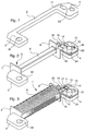
- the electrical circuit is in the form of a printed circuit 18 as shown in perspective on the FIG. 6 and in plan in FIG. 7.
- This printed circuit 18 is provided with conductive tracks 19. It is able to provide to the motor advance pulses generated so usual by a quartz 31 and an integrated circuit 30.
- the printed circuit 18 is applied against plate 10 and, as shown in Figure 7, conductive tracks 20 and 21, capable of supplying the motor, face each other to the corresponding output wires 11 and 12 of winding 9 of the coil 1.
- the leads 11, 12 are soldered to the conductive tracks 20 and 21.
- Figure 8 is a section along line VIII-VIII of Figure 7 and the Figure 9 is an enlargement of zone IX drawn in Figure 8.
- the printed circuit 18 is arranged against plate 10 as described in the paragraph above we apply, through the hole 17 of the ear 4 and the hole 16 of plate 10, these holes being arranged in a row, a pin 27 on wire 11 and another pin 28 on wire 12.
- the plate 10 carries a first stud 22 formed by molding the plate 10 and a second stud 24 molded in the same way.
- this circuit 18 includes a first hole 23 through which the first stud 22 and a second hole 25 crossed by the second stud 24 when the circuit 18 is applied to plate 10.
- the function of the stud 22 is to guide and to orient the circuit 18, while the function of the nipple 24 is to fix said circuit 18, this fixing being performed by heating the end of said second stud 24 to finally install the printed circuit 18 on the plate 10.
Landscapes
- Engineering & Computer Science (AREA)
- Power Engineering (AREA)
- Manufacturing & Machinery (AREA)
- Physics & Mathematics (AREA)
- General Physics & Mathematics (AREA)
- Microelectronics & Electronic Packaging (AREA)
- Insulation, Fastening Of Motor, Generator Windings (AREA)
Abstract
Description
- la figure 1 montre le noyau de la bobine avec deux oreilles;
- la figure 2 montre le corps de bobine équipé de deux flasques et d'une plaque faisant partie d'un des flasques;
- la figure 3 montre la bobine terminée avec son enroulement, ses fils de sortie étant incrustés dans la plaque;
- la figure 4 est une coupe partielle de la bobine montrant comment on s'y prend pour la contrôler;
- la figure 5 est un agrandissement de la région V de la figure 4;
- la figure 6 montre un circuit imprimé attaché à la bobine ainsi que la manière de faire pour souder les fils de sortie de l'enroulement aux pistes du circuit;
- la figure 7 est une vue de dessus de ce qui est représenté en perspective à la figure 6;
- la figure 8 est une coupe selon la figure VIII-VIII représentée en figure 7;
- la figure 9 est un agrandissement de la région IX de la figure 8;
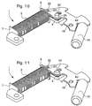
- la figure 10 est une vue de dessous de l'ensemble montré en figure 6, le circuit imprimé n'étant pas encore fixé à la plaque, et
- la figure 11 est une vue similaire à celle de la figure 10 dans laquelle le circuit imprimé est fixé à la plaque.
Claims (8)
- Bobine (1) de moteur actionnant l'affichage d'une pièce d'horlogerie, cette bobine comportant un noyau magnétisable (2) dont chacune des extrémités comprend une oreille (3, 4), un corps de bobine (5) isolant constitué d'un tube (6) entourant le noyau (2) et d'un flasque (7, 8) disposé à chacune des extrémités du tube (6), et un enroulement (9) bobiné sur le corps de bobine (5), caractérisée par le fait qu'une plaque (10), faite d'une pièce avec l'un (8) des flasques et arrangée pour venir reposer sur l'une (4) des oreilles du noyau (2), sert de point d'ancrage pour les fils de sortie (11, 12) de l'enroulement (9) par incrustation des zones terminales (13, 14) de chacun de ces fils dans la plaque (10).
- Bobine selon la revendication 1, caractérisée par le fait qu'avant d'aboutir aux zones terminales (13, 14) d'incrustation, les fils de sortie (11, 12) suivent un canal (15) pratiqué dans la plaque (10), un trou (16, 17) disposé perpendiculairement aux fils (11, 12) et aboutissant dans ce canal (15) étant foré à la fois dans la plaque (10) et dans l'oreille (4).
- Bobine selon la revendication 2, caractérisée par le fait qu'un circuit imprimé (18) muni de pistes conductrices (19) et apte à fournir au moteur des impulsions d'avance est appliqué contre la plaque (10), les pistes conductrices (20, 21) alimentant le moteur faisant face aux fils de sortie (11, 12) correspondants de l'enroulement (9), lesdites pistes étant soudées audits fils au droit du trou (16, 17) foré à la fois dans la plaque (10) et dans l'oreille (4).
- Bobine selon la revendication 3, caractérisée par le fait que la plaque (10) porte un premier téton (22) traversant un premier trou (23) pratiqué dans le circuit imprimé (18) pour guider et orienter ledit circuit et un second téton (24) traversant un second trou (25) dudit circuit pour le fixer sur ladite plaque (10).
- Bobine selon la revendication 1, caractérisée par le fait que le corps de bobine (5) et la plaque (10) sont moulés en une seule pièce.
- Procédé de contrôle de bienfacture de la bobine (1) exécutée selon la revendication 1, caractérisé par le fait qu'on applique dans la zone terminale (13, 14) de chacun des fils de sortie (11, 12) une sonde de mesure (26) entaillant la plaque (10) et venant en contact avec le fil (11, 12) pour mesurer la résistance électrique de l'enroulement (9) de la bobine (1).
- Procédé de connexion des fils de sortie (11, 12) de l'enroulement (9) de la bobine (1) aux pistes conductrices (20, 21) du circuit imprimé (18), fils et pistes étant exécutés selon la revendication 3, caractérisé par le fait qu'on applique à travers le trou (16, 17) traversant la plaque (10) et l'oreille (4) une goupille (27, 28) sur chacun des fils de sortie (11, 12) et qu'on soude ledit fil sur ladite piste correspondante par thermocompression.
- Procédé de fixation du circuit imprimé (18) sur la plaque (10), ces deux éléments étant exécutés selon la revendication 4, caractérisé par le fait qu'on chauffe l'extrémité du second téton (24) pour river ledit circuit imprimé (18) sur ladite plaque (10).
Priority Applications (2)
| Application Number | Priority Date | Filing Date | Title |
|---|---|---|---|
| DE69731079T DE69731079D1 (de) | 1997-07-15 | 1997-07-15 | Spule für Motoren für Zeitwerke |
| EP97112022A EP0892481B1 (fr) | 1997-07-15 | 1997-07-15 | Bobine de moteur pour pièce d'horlogerie |
Applications Claiming Priority (1)
| Application Number | Priority Date | Filing Date | Title |
|---|---|---|---|
| EP97112022A EP0892481B1 (fr) | 1997-07-15 | 1997-07-15 | Bobine de moteur pour pièce d'horlogerie |
Publications (2)
| Publication Number | Publication Date |
|---|---|
| EP0892481A1 true EP0892481A1 (fr) | 1999-01-20 |
| EP0892481B1 EP0892481B1 (fr) | 2004-10-06 |
Family
ID=8227060
Family Applications (1)
| Application Number | Title | Priority Date | Filing Date |
|---|---|---|---|
| EP97112022A Expired - Lifetime EP0892481B1 (fr) | 1997-07-15 | 1997-07-15 | Bobine de moteur pour pièce d'horlogerie |
Country Status (2)
| Country | Link |
|---|---|
| EP (1) | EP0892481B1 (fr) |
| DE (1) | DE69731079D1 (fr) |
Citations (5)
| Publication number | Priority date | Publication date | Assignee | Title |
|---|---|---|---|---|
| GB2012117A (en) * | 1977-11-26 | 1979-07-18 | Citizen Watch Co Ltd | Coil assembly with U.V. cureable protective covering |
| JPS5577342A (en) * | 1978-12-05 | 1980-06-11 | Citizen Watch Co Ltd | Coil for watch |
| JPS55144740A (en) * | 1979-04-25 | 1980-11-11 | Citizen Watch Co Ltd | Construction and manufacturing method of coil unit for timing step motor |
| EP0582714A1 (fr) * | 1991-04-30 | 1994-02-16 | Kabushiki Kaisha Sankyo Seiki Seisakusho | Stator de machine electrique rotative |
| US5531390A (en) * | 1991-02-25 | 1996-07-02 | Gustafson; Ake | Method of winding a coil on a chuck having guide pins |
-
1997
- 1997-07-15 DE DE69731079T patent/DE69731079D1/de not_active Expired - Lifetime
- 1997-07-15 EP EP97112022A patent/EP0892481B1/fr not_active Expired - Lifetime
Patent Citations (5)
| Publication number | Priority date | Publication date | Assignee | Title |
|---|---|---|---|---|
| GB2012117A (en) * | 1977-11-26 | 1979-07-18 | Citizen Watch Co Ltd | Coil assembly with U.V. cureable protective covering |
| JPS5577342A (en) * | 1978-12-05 | 1980-06-11 | Citizen Watch Co Ltd | Coil for watch |
| JPS55144740A (en) * | 1979-04-25 | 1980-11-11 | Citizen Watch Co Ltd | Construction and manufacturing method of coil unit for timing step motor |
| US5531390A (en) * | 1991-02-25 | 1996-07-02 | Gustafson; Ake | Method of winding a coil on a chuck having guide pins |
| EP0582714A1 (fr) * | 1991-04-30 | 1994-02-16 | Kabushiki Kaisha Sankyo Seiki Seisakusho | Stator de machine electrique rotative |
Non-Patent Citations (2)
| Title |
|---|
| PATENT ABSTRACTS OF JAPAN vol. 004, no. 121 (E - 023) 27 August 1980 (1980-08-27) * |
| PATENT ABSTRACTS OF JAPAN vol. 005, no. 015 (E - 043) 29 January 1981 (1981-01-29) * |
Also Published As
| Publication number | Publication date |
|---|---|
| DE69731079D1 (de) | 2004-11-11 |
| EP0892481B1 (fr) | 2004-10-06 |
Similar Documents
| Publication | Publication Date | Title |
|---|---|---|
| CN101641757B (zh) | 熔断器和用于制造熔断器的方法 | |
| US7411478B2 (en) | Coil component | |
| EP2085981A1 (fr) | Borne et dispositif de bobine l'utilisant | |
| EP0589748B1 (fr) | Procédé pour permettre le montage d'une puce sur un substrat | |
| JP6636719B2 (ja) | 電線接続用端子および電線接続用端子と電線の接合方法 | |
| CH691718A5 (fr) | Bobine de moteur pour pièce d'horlogerie et assemblage de cette bobine et d'un circuit imprimé. | |
| EP0892481B1 (fr) | Bobine de moteur pour pièce d'horlogerie | |
| FR2812387A1 (fr) | Dispositif detecteur de rotation | |
| FR2510827A1 (fr) | Dispositif collecteur pour petits moteurs electriques | |
| CN113972543B (zh) | 线缆连电路板的焊接辅助件、线缆、电路板、组件和方法 | |
| FR2742007A1 (fr) | Procede et dispositif de raccordement d'un cable a un connecteur electrique | |
| FR2739731A1 (fr) | Procede de raccordement de micro-cables coaxiaux aux pistes d'un circuit imprime | |
| JP4833444B2 (ja) | レーザガイド装置 | |
| FR2473780A1 (fr) | Relais electromagnetique | |
| EP1286384A1 (fr) | Lampe avec dispositif anti-explosion | |
| WO2019218948A1 (fr) | Élément de brasage auxiliaire pour très petits plots, et ensemble de fabrication, procédé de fabrication et procédé de brasage auxiliaire associé | |
| FR3096452A1 (fr) | Ensemble de capteur de débit massique et procédé de fabrication d’un ensemble de capteur de débit massique | |
| TW460887B (en) | Lead conductor for thermal fuse and thermal fuse | |
| JPH10153621A (ja) | 電力量計の電圧コイル端子構造 | |
| US8003894B2 (en) | Soldering nest for a bus bar | |
| FR2541524A1 (fr) | Procede pour mettre en contact, par echauffement et au moyen d'un materiau de soudure, des fils metalliques electriquement conducteurs | |
| JP2002134250A (ja) | セラミックヒータ | |
| EP0450996A1 (fr) | Dispositif pour fixer un câble coaxial, et le relier à la masse d'une plaque de circuit imprimé | |
| JP2807748B2 (ja) | 電気コネクタの組立方法及びそれに使用するはんだ付リードフレーム | |
| JP2003161658A (ja) | 熱電対における温度測定補助具 |
Legal Events
| Date | Code | Title | Description |
|---|---|---|---|
| PUAI | Public reference made under article 153(3) epc to a published international application that has entered the european phase |
Free format text: ORIGINAL CODE: 0009012 |
|
| AK | Designated contracting states |
Kind code of ref document: A1 Designated state(s): CH DE FR GB LI |
|
| AX | Request for extension of the european patent |
Free format text: AL;LT;LV;RO;SI |
|
| 17P | Request for examination filed |
Effective date: 19990720 |
|
| AKX | Designation fees paid |
Free format text: CH DE FR GB LI |
|
| RAP1 | Party data changed (applicant data changed or rights of an application transferred) |
Owner name: ETA SA MANUFACTURE HORLOGERE SUISSE |
|
| GRAP | Despatch of communication of intention to grant a patent |
Free format text: ORIGINAL CODE: EPIDOSNIGR1 |
|
| GRAS | Grant fee paid |
Free format text: ORIGINAL CODE: EPIDOSNIGR3 |
|
| GRAA | (expected) grant |
Free format text: ORIGINAL CODE: 0009210 |
|
| AK | Designated contracting states |
Kind code of ref document: B1 Designated state(s): CH DE FR GB LI |
|
| PG25 | Lapsed in a contracting state [announced via postgrant information from national office to epo] |
Ref country code: GB Free format text: LAPSE BECAUSE OF FAILURE TO SUBMIT A TRANSLATION OF THE DESCRIPTION OR TO PAY THE FEE WITHIN THE PRESCRIBED TIME-LIMIT Effective date: 20041006 |
|
| REG | Reference to a national code |
Ref country code: GB Ref legal event code: FG4D Free format text: NOT ENGLISH |
|
| REG | Reference to a national code |
Ref country code: CH Ref legal event code: EP |
|
| REF | Corresponds to: |
Ref document number: 69731079 Country of ref document: DE Date of ref document: 20041111 Kind code of ref document: P |
|
| PG25 | Lapsed in a contracting state [announced via postgrant information from national office to epo] |
Ref country code: DE Free format text: LAPSE BECAUSE OF FAILURE TO SUBMIT A TRANSLATION OF THE DESCRIPTION OR TO PAY THE FEE WITHIN THE PRESCRIBED TIME-LIMIT Effective date: 20050108 |
|
| REG | Reference to a national code |
Ref country code: CH Ref legal event code: NV Representative=s name: ICB INGENIEURS CONSEILS EN BREVETS SA |
|
| GBV | Gb: ep patent (uk) treated as always having been void in accordance with gb section 77(7)/1977 [no translation filed] |
Effective date: 20041006 |
|
| PLBE | No opposition filed within time limit |
Free format text: ORIGINAL CODE: 0009261 |
|
| STAA | Information on the status of an ep patent application or granted ep patent |
Free format text: STATUS: NO OPPOSITION FILED WITHIN TIME LIMIT |
|
| 26N | No opposition filed |
Effective date: 20050707 |
|
| PG25 | Lapsed in a contracting state [announced via postgrant information from national office to epo] |
Ref country code: FR Free format text: LAPSE BECAUSE OF NON-PAYMENT OF DUE FEES Effective date: 20060331 |
|
| REG | Reference to a national code |
Ref country code: FR Ref legal event code: ST Effective date: 20060331 |
|
| PGFP | Annual fee paid to national office [announced via postgrant information from national office to epo] |
Ref country code: CH Payment date: 20160621 Year of fee payment: 20 |
|
| REG | Reference to a national code |
Ref country code: CH Ref legal event code: PL |