EP0892703B1 - Lotterieausgabevorrichtung - Google Patents
Lotterieausgabevorrichtung Download PDFInfo
- Publication number
- EP0892703B1 EP0892703B1 EP97920202A EP97920202A EP0892703B1 EP 0892703 B1 EP0892703 B1 EP 0892703B1 EP 97920202 A EP97920202 A EP 97920202A EP 97920202 A EP97920202 A EP 97920202A EP 0892703 B1 EP0892703 B1 EP 0892703B1
- Authority
- EP
- European Patent Office
- Prior art keywords
- burster
- weakness
- line
- tickets
- articles
- Prior art date
- Legal status (The legal status is an assumption and is not a legal conclusion. Google has not performed a legal analysis and makes no representation as to the accuracy of the status listed.)
- Expired - Lifetime
Links
Images

Classifications
-
- B—PERFORMING OPERATIONS; TRANSPORTING
- B41—PRINTING; LINING MACHINES; TYPEWRITERS; STAMPS
- B41J—TYPEWRITERS; SELECTIVE PRINTING MECHANISMS, i.e. MECHANISMS PRINTING OTHERWISE THAN FROM A FORME; CORRECTION OF TYPOGRAPHICAL ERRORS
- B41J11/00—Devices or arrangements of selective printing mechanisms, e.g. ink-jet printers or thermal printers, for supporting or handling copy material in sheet or web form
- B41J11/66—Applications of cutting devices
- B41J11/70—Applications of cutting devices cutting perpendicular to the direction of paper feed
-
- B—PERFORMING OPERATIONS; TRANSPORTING
- B26—HAND CUTTING TOOLS; CUTTING; SEVERING
- B26F—PERFORATING; PUNCHING; CUTTING-OUT; STAMPING-OUT; SEVERING BY MEANS OTHER THAN CUTTING
- B26F3/00—Severing by means other than cutting; Apparatus therefor
- B26F3/002—Precutting and tensioning or breaking
-
- B—PERFORMING OPERATIONS; TRANSPORTING
- B65—CONVEYING; PACKING; STORING; HANDLING THIN OR FILAMENTARY MATERIAL
- B65H—HANDLING THIN OR FILAMENTARY MATERIAL, e.g. SHEETS, WEBS, CABLES
- B65H35/00—Delivering articles from cutting or line-perforating machines; Article or web delivery apparatus incorporating cutting or line-perforating devices, e.g. adhesive tape dispensers
- B65H35/10—Delivering articles from cutting or line-perforating machines; Article or web delivery apparatus incorporating cutting or line-perforating devices, e.g. adhesive tape dispensers from or with devices for breaking partially-cut or perforated webs, e.g. bursters
-
- G—PHYSICS
- G07—CHECKING-DEVICES
- G07B—TICKET-ISSUING APPARATUS; FARE-REGISTERING APPARATUS; FRANKING APPARATUS
- G07B3/00—Machines for issuing preprinted tickets
-
- Y—GENERAL TAGGING OF NEW TECHNOLOGICAL DEVELOPMENTS; GENERAL TAGGING OF CROSS-SECTIONAL TECHNOLOGIES SPANNING OVER SEVERAL SECTIONS OF THE IPC; TECHNICAL SUBJECTS COVERED BY FORMER USPC CROSS-REFERENCE ART COLLECTIONS [XRACs] AND DIGESTS
- Y10—TECHNICAL SUBJECTS COVERED BY FORMER USPC
- Y10T—TECHNICAL SUBJECTS COVERED BY FORMER US CLASSIFICATION
- Y10T225/00—Severing by tearing or breaking
- Y10T225/10—Methods
-
- Y—GENERAL TAGGING OF NEW TECHNOLOGICAL DEVELOPMENTS; GENERAL TAGGING OF CROSS-SECTIONAL TECHNOLOGIES SPANNING OVER SEVERAL SECTIONS OF THE IPC; TECHNICAL SUBJECTS COVERED BY FORMER USPC CROSS-REFERENCE ART COLLECTIONS [XRACs] AND DIGESTS
- Y10—TECHNICAL SUBJECTS COVERED BY FORMER USPC
- Y10T—TECHNICAL SUBJECTS COVERED BY FORMER US CLASSIFICATION
- Y10T225/00—Severing by tearing or breaking
- Y10T225/10—Methods
- Y10T225/12—With preliminary weakening
-
- Y—GENERAL TAGGING OF NEW TECHNOLOGICAL DEVELOPMENTS; GENERAL TAGGING OF CROSS-SECTIONAL TECHNOLOGIES SPANNING OVER SEVERAL SECTIONS OF THE IPC; TECHNICAL SUBJECTS COVERED BY FORMER USPC CROSS-REFERENCE ART COLLECTIONS [XRACs] AND DIGESTS
- Y10—TECHNICAL SUBJECTS COVERED BY FORMER USPC
- Y10T—TECHNICAL SUBJECTS COVERED BY FORMER US CLASSIFICATION
- Y10T225/00—Severing by tearing or breaking
- Y10T225/30—Breaking or tearing apparatus
- Y10T225/35—Work-parting pullers [bursters]
-
- Y—GENERAL TAGGING OF NEW TECHNOLOGICAL DEVELOPMENTS; GENERAL TAGGING OF CROSS-SECTIONAL TECHNOLOGIES SPANNING OVER SEVERAL SECTIONS OF THE IPC; TECHNICAL SUBJECTS COVERED BY FORMER USPC CROSS-REFERENCE ART COLLECTIONS [XRACs] AND DIGESTS
- Y10—TECHNICAL SUBJECTS COVERED BY FORMER USPC
- Y10T—TECHNICAL SUBJECTS COVERED BY FORMER US CLASSIFICATION
- Y10T225/00—Severing by tearing or breaking
- Y10T225/30—Breaking or tearing apparatus
- Y10T225/371—Movable breaking tool
-
- Y—GENERAL TAGGING OF NEW TECHNOLOGICAL DEVELOPMENTS; GENERAL TAGGING OF CROSS-SECTIONAL TECHNOLOGIES SPANNING OVER SEVERAL SECTIONS OF THE IPC; TECHNICAL SUBJECTS COVERED BY FORMER USPC CROSS-REFERENCE ART COLLECTIONS [XRACs] AND DIGESTS
- Y10—TECHNICAL SUBJECTS COVERED BY FORMER USPC
- Y10T—TECHNICAL SUBJECTS COVERED BY FORMER US CLASSIFICATION
- Y10T225/00—Severing by tearing or breaking
- Y10T225/30—Breaking or tearing apparatus
- Y10T225/393—Web restrainer
Definitions
- This invention relates generally to ticket dispensing systems and more particularly to an improved system and method for dispensing lottery tickets.
- the invention relates to a bursting mechanism according to the preamble of claim 1 and a method of dispensing lottery tickets or planar articles according to the preamble of claim 5.
- a bursting mechanism according to the preamble of claim 1
- a method of dispensing lottery tickets or planar articles according to the preamble of claim 5.
- An example of such a mechanism and method is disclosed by US 4 982 337 A.
- State sponsored lotteries are now a popular and accepted method of generating revenue and providing entertainment.
- One popular form of lottery uses an instant lottery ticket on which winning or non-winning combinations are pre-printed before distribution and the player knows immediately after purchasing the ticket whether or not it is a winning ticket.
- a common system for distributing instant lottery tickets includes a large number of ticket dispensing machines located at drug stores, supermarkets, convenient stores and the like. Common concerns associated with such lottery ticket dispensing machines are the speed with which they dispense the tickets, the security or anti-theft characteristics of the dispenser and the ability to accurately provide an accounting for the tickets sold from each machine.
- a problem associated with the dispensing of lottery tickets stored in a fanfold stream is how to ensure that each ticket as it becomes the leading ticket will be separated from the next following ticket precisely along the joinder line between the tickets.
- a line of weakness such as a perforation line is provided to define each ticket and to permit fanfolding of the stream of connected tickets.
- each fold contains a single ticket but in alternative embodiments, a number of tickets for example five or more may be provided within each fold.
- Lottery tickets conventionally are constructed from laminated layers of paper or cardboard and as such are relatively stiff and inflexible.
- Prior art solutions to these problems include using a knife edge or cutting blade to slice through the stream of tickets. This is not desirable because the knife edge may cut through the tickets at any point such as in the middle of the ticket. Therefore, a highly precise alignment device usually must be provided with a knife edge to bring it into precise alignment with the joinder line between the tickets.
- the burster wheel of the '337 patent is in the form of a circular burster blade which has a dull rounded edge that does not cut the stream of tickets but rather exerts pressure against the top of the stream of tickets to deflect the tickets and separate them along the line of weakness separating the tickets.
- the burster wheel in the '337 patent is moved back and forth across the connected tickets by a motorized cable and pulley system.
- the manufacturing tolerances of the tickets vary greatly.
- the length of individual tickets with respect to other tickets in the same fanfold stream varies a relatively large amount and may be on the order of 1/16 inch or so.
- the burster wheel may be aligned with the majority of the lines of weakness in a given fanfold stream, due to the variations in the lengths of the tickets, it is commonly misaligned with other lines of weakness and thereby may provide an ineffective separation or fail to separate the tickets at all.
- the perforations or lines of weakness between the individual tickets are not uniformly formed such that a greater force may be required from the bursting wheel to separate one line of weakness than another line of weakness in the same fanfold stream. Tickets are manufactured with varying degrees of perforation quality.
- perforation quality varies greatly due to a number of variables including, the ticket printing company, ticket stock, ticket coatings and the like. Aside from these variables, perforation quality can still vary within the same game with the same ticket press run. The consistency of ticket perforations vary not only from company to company but also from game to game provided by the same manufacturer.
- Another objective of the invention is to provide an improved burster mechanism which can overcome variations in the nominal ticket size and perforation quality and still provide an effective, reliable and accurate separation of the tickets.
- a still further objective has been to provide such a burster mechanism which is more reliable and less susceptible to malfunctioning or maintenance problems.
- the present invention provides a bursting mechanism in accordance with claim 1 and a method in accordance with claim 5.
- the burster mechanism in a preferred embodiment has a burster with a generally planar contact surface around the perimeter thereof as opposed to the rounded or semi-circular surface in prior burster wheels.
- the planar contact surface intersects the stream of fanfold tickets and thereby separates the adjacent tickets along the line of weakness or perforation therebetween.
- the burster having a planar contact surface allows for a more consistent separation of the tickets irrespective of the variation in the tickets, perforations and materials. Moreover, a consistent separation of the tickets at the perforation can be obtained even with a misalignment or a spacing between the path of the burster and the perforation.
- the effective range or margin of error upstream or downstream from the line of weakness or perforation is significantly greater with the burster having a planar contact surface than that of the prior art semi-circular burster wheel.
- the increased margin of error with respect to the alignment of the path of the burster and the perforation produces a more reliable and consistent separation of the tickets irrespective of variations in the tickets.
- a further improvement of the burster mechanism according to this invention is the replacement of the motorized cable and pulley system for translating the burster wheel back and forth across the tickets with either a motor driven threaded screw drive mechanism or a toothed rack and gear drive mechanism.
- These mechanisms are less susceptible to breakage and provide a more efficient transmission of power to translate the burster wheel across the path of the tickets.
- an improved lottery ticket dispenser which includes the screw drive mechanism or toothed rack and gear mechanism is expected to require fewer repairs and more reliable service in the field.
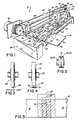
- a transport mechanism and burster assembly 10 is shown in Fig. 1 for a lottery ticket dispenser (not shown).
- a typical lottery ticket dispenser is shown in U.S. Patent No. 4,982,337.
- a plurality of individual tickets 12 are connected in a fanfold strip or stream 14. Individual tickets 12 are separated from an adjacent ticket by a line of weakness 16 which typically comprises perforations.
- the tickets 12 are provided typically by the state authority in a fanfold stack which is compact and easily transportable and typically include as many as 1,500 tickets in each stack.
- a stack of fanfold tickets 12 are contained in a storage compartment (not shown) in the lottery ticket dispenser.
- Each ticket 12 is connected to an adjacent ticket 12 along the line of weakness 16 and it will be understood that each successive following ticket 12 is separable from an adjacent ticket by a similar line of weakness 16.
- the fanfold stream 14 of tickets 12 is fed along a dispensing path from the storage compartment toward an outlet (not shown).
- the stream 14 is transported along the dispensing path by the transport mechanism 10 including opposed upper feed rollers 18 and lower feed rollers 20 and opposed upper exit rollers 22 and lower exit rollers 24 as in Fig. 1.
- a generally circular burster wheel 26 is mounted for rotation between spaced downwardly extending flanges 28 of a burster block 30.
- the burster wheel 26 is mounted for rotation on the burster block 30 on an axle 32 extending through cylindrical hubs 34 on each face of the burster wheel 26 and into the spaced flanges 28.
- the burster block 30 includes a bore hole 36 through which extends a lower burster bar 38.
- the burster block 30 also includes an upper cutout 40 which substantially surrounds an upper burster bar 42.
- the burster block 30 is mounted for a translation along the upper and lower burster bars 38, 42 between opposed side brackets 44, 46 of the transport mechanism 10.
- a cable 48 extends from a first face of the burster block 30 through an aperture 50 in the side bracket 44 and around an upper idler roller 52 and a lower idler roller 54.
- the cable 48 also extends from an opposite face of the burster block 30 through an aperture 56 in the side bracket 46 and is wound around a driven roller 58 driven by a motor 60.
- the cable 48 preferably includes a tensioning spring 62.
- the idler rollers 52, 54 are each mounted on a post 70, 72, respectively, for rotation and include an arcuate cradle 74 in which the cable 48 contacts the roller 52, 54 (Fig. 2).
- the arcuate configuration of the cradle 74 minimizes stress concentration for the roller 52 or 54 and cable 48 interface and the likelihood that the cable 48 will bind or freeze up when passing over the roller 52 or 54.
- the cable 48 passes over both the upper and lower idler rollers 52, 54 and contacts each roller in a 90° arc thereby minimizing the contact friction with each of the rollers 52, 54 and reducing the failure rate of the components.
- the upper exit rollers 22 are journaled on a common upper exit shaft 63 and the lower exit rollers 24 are journaled similarly on a lower exit shaft 64.
- the upper feed rollers 18 are journaled on a common upper feed shaft 66 and the lower feed rollers 20 are journaled on a common lower feed shaft 68.
- the shafts 62, 64, 66, 68 extend between the bracket 44 and a housing 69 containing a motor (not shown) for rotationally driving the shafts 63, 64, 66, 68 to advance the stream 14 of tickets 12.
- the motors and operation of the transport mechanism 10 are controlled by a control circuit (not shown) as is well known in the art.
- the transport mechanism 10 may include an aligning mechanism comprising a code wheel (not shown) or the like as is disclosed in the '337 patent.
- the burster block 30 and burster wheel 26 When the burster block 30 and burster wheel 26 are moved from the rest position illustrated in Fig. 1 toward interception with the dispensing path of the stream 14 of tickets 12 through the action of the cable 48 and motor, the burster wheel 26 will come into contact with the stream 14 of tickets 12 at the side thereof initially then across the stream 14 of tickets 12 to burst the adjacent tickets 12 apart along the line of weakness 16.
- the burster block 30 is moved from right to left as shown in Fig. 1 to burst the leading ticket 12, then left to right to burst the next leading ticket 12, and so on.
- the burster block 30 and wheel 26 translate along the bars to intersect the dispensing path of the stream 14 of tickets 12 perpendicularly. As a result, the path of the burster wheel 26 on the tickets 12 is generally parallel to the line of weakness 16 separating the adjacent tickets 12.
- the burster wheel 26 includes a planar contact surface 76 around the perimeter thereof as shown particularly in Fig. 4.
- the overall outer diameter of the burster wheel 26 is 0.912 inches and the diameter of the central hubs 34 are 0.185 inches.
- the planar contact surface 76 in a presently preferred embodiment is 0.187 inches wide and adjacent each edge of the planar contact surface is a 0.062 inch radius 78.
- the burster wheel 26 is fabricated from nylon or black acetal.
- the improved burster wheel 26 of the present invention advantageously provides an increased effective separation range 80 in which the wheel contacts the stream 14 of tickets 12 and provides an effective separation of the tickets 12.
- the burster wheel 26 of this invention provides the larger effective range 80 as shown in Fig. 5 in which the wheel 26 may contact the stream 14 of tickets 12 and still separate the adjacent tickets 12 along the line of weakness 16 as compared to a range of operation 82 provided by a prior art burster wheel 84 (Fig. 3) having a rounded outer edge contact surface 86.
- the effective range of the presently preferred embodiment of the burster wheel is a total of about 1/4 of an inch or 1 /8 of an inch on either side of the line of weakness 16 separating the adjacent tickets 12.
- FIGs. 6 and 7 a second presently preferred embodiment of the transport mechanism according to this invention is shown. Like reference numerals are used in Figs. 6 and 7 to indicate elements of the invention which are similar to those shown in Fig. 1.
- the fanfold stream 14 of tickets 12 is fed along a dispensing path from the storage compartment toward an outlet (not shown).
- the generally circular burster wheel 26 is mounted for rotation between spaced downwardly extending flanges 28 of a modified burster block 31.
- the burster wheel 26 is mounted for rotation on the burster block 31 on an axle 32 extending into the spaced flanges 28.
- the burster block 31 includes a bore hole 37 through which extends a burster bar 39.
- the burster block 31 also includes a semi-circular upper cutout 41 which includes a plurality of spaced arcuate grooves 43 which are separated from one another by arcuate ribs 45 (Fig. 7).
- the upper cutout 41 is sized and configured to mate with a screw drive 49 having a spiral screw thread 51 on the outer circumference thereof.
- the screw drive 49 and screw thread 51 is a ten degree modified square thread or other buttress type thread for meshing with the grooves 43 and ribs 45 on the burster block 31.
- the burster block 31 is mounted for a translation along the burster bars 39 between opposed side brackets 53, 55 of the transport mechanism 11.
- the screw drive 49 extends between the brackets 53, 55 and is rotationally driven by a motor 57 mounted on the external side of the bracket 53 as shown in Fig. 6. Actuation of the motor 57 to rotate the screw drive 49 in a first direction as shown by arrow A in Fig. 7 translates the burster block 31 in a corresponding direction as shown by arrow B to pass the burster wheel 26 across the path of the tickets 14 and separate adjacent tickets 12 along the perforation 16. Similarly, actuation of the motor 57 to rotate the screw drive 49 in a second direction as shown by arrow C translates the burster block 31 in a corresponding direction as shown by arrow D to once again separate subsequent adjacent tickets 12 along the perforation 16.
- the mating screw drive 49 and burster block 31 provide increased reliability and improved performance over previous mechanism for translating the burster wheel 26 to separate the tickets 12.
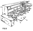
- FIG. 8 a third presently preferred embodiment of the transport mechanism according to this invention is shown. Like reference numerals of Fig. 6 are used in Fig. 8 to indicate similar elements of the invention.
- the fanfold stream 14 of tickets 12 is fed along a dispensing path from the storage compartment toward an outlet (not shown).
- the generally circular burster wheel 26 is mounted for rotation between spaced downwardly extending flanges 28 of a modified burster block 31a.
- the burster wheel 26 is mounted for rotation on the burster block 31a on an axle 32 extending into the spaced flanges 28.
- the burster block 31a includes a bore hole 37 through which extends a burster bar 39.
- a rack 80 having a plurality of upwardly directed teeth 82 on an upper surface thereof is fixedly mounted between the side brackets 53, 55.
- a motor 84 is mounted on a bracket 86 to the modified burster block 31 a and a rotationally driven shaft 88 projects from the motor 84.
- a spur gear 90 or the like is mounted on the shaft 88 and engages the teeth 82 on the rack 80.
- the gear 90 engages the teeth 82 to move the motor 84 and burster block 31a in a first direction so the burster wheel 26 intersects the fanfold stream 14 of tickets 12.
- reverse rotation of the shaft 88 moves the burster block 31a and wheel 26 in a second direction opposite the first direction to there again intersect the fanfold stream 14.
Landscapes
- Physics & Mathematics (AREA)
- General Physics & Mathematics (AREA)
- Life Sciences & Earth Sciences (AREA)
- Forests & Forestry (AREA)
- Engineering & Computer Science (AREA)
- Mechanical Engineering (AREA)
- Ticket-Dispensing Machines (AREA)
- Credit Cards Or The Like (AREA)
Claims (8)
- Berstmechanismus zum Trennen von individuellen planaren Artikeln (12) in einem Leporellostapel (14), der entlang einer Sollbruchlinie (16) miteinander verbunden ist, wobei der Berstmechanismus Folgendes umfasst: einen Transportmechanismus (10) zum Zuführen des Stapels über einen Vorschubpfad zu einem Auslass, eine auf dem Vorschubpfad befindliche Berststation und eine Berstvorrichtung (26), die entfernbar so montiert ist, dass sie den Vorschubpfad schneidet und mit dem genannten Stapel in der Nähe der Sollbruchlinie (16) an der Berststation in Kontakt gebracht werden kann, wobei die Berstvorrichtung (26) eine Kontaktfläche (76) hat, die den Stapel (14) kontaktiert und das Paar von benachbarten Artikeln (12) entlang der Sollbruchlinie trennt, dadurch gekennzeichnet, dass die Berstvorrichtung (26) eine planare Kontaktfläche (76) hat, die den Stapel (14) kontaktiert und das Paar benachbarter Artikel (12) entlang der Sollbruchlinie selbst dann trennt, wenn die planare Kontaktfläche (76) von der Sollbruchlinie (16) nach dem Kontakt mit dem Stapel (14) versetzt ist.
- Berstmechanismus nach Anspruch 1, ferner umfassend wenigstens eine Zufuhrrolle (18, 20) an der Berststation, die die genannten Artikel (12) an einer Stelle entlang dem Vorschubpfad oberhalb der Sollbruchlinie (16) kontaktiert, und wenigstens eine Abfuhrrolle (22, 24) an der Berststation, die die Artikel an einer Stelle entlang dem Vorschubpfad unterhalb der Sollbruchlinie kontaktiert, wobei die Ab- und Zufuhrrollen jeweils rotational angetrieben werden und zusammenwirken, um die Artikel zu halten, während die Berstvorrichtung das Paar benachbarter Artikel entlang der Sollbruchlinie trennt.
- Berstmechanismus nach Anspruch 1 oder Anspruch 2, wobei die Berststation ferner einen rotational angetriebenen Spindelantrieb (49) und einen Block (31) mit einer Mehrzahl von mit dem Spindelantrieb kämmenden Nuten (43) aufweist, wobei die Berstvorrichtung (26) so an dem Block montiert ist, dass die Rotation des Spindelantriebs die Berstvorrichtung mit dem Stapel (14) in Kontakt bringt, um dadurch das benachbarte Paar Artikel entlang der Sollbruchlinie (16) zu trennen.
- Berstmechanismus nach Anspruch 1 oder Anspruch 2, wobei die Berststation ferner ein rotational angetriebenes Geradstirnrad (90), einen Block (31a) mit dem darauf montierten Geradstirnrad, eine Zahnstange (80) mit einer Mehrzahl von mit dem Geradstirnrad kämmenden Zähnen (82) umfasst, wobei die Berstvorrichtung (26) so an dem Block montiert ist, dass die Rotation des Geradstirnrades die Berstvorrichtung mit dem Stapel (14) in Kontakt bringt, um dadurch das benachbarte Paar von Artikeln entlang der Sollbruchlinie (16) zu trennen.
- Verfahren zum Ausgeben von Lotterielosen oder planaren Artikeln in einem Leporellostapel, der entlang einer Sollbruchlinie miteinander verbunden ist, wobei das Verfahren die folgenden Schritte umfasst: Zuführen einer Mehrzahl von in einem Leporellostapel (14) miteinander verbundenen Losen oder Artikeln (12) über einen Vorschubpfad, wobei ein Paar von benachbarten der genannten Lose oder Artikel (12) entlang der Sollbruchlinie (16) dazwischen voneinander getrennt werden kann; Bewegen einer Berstvorrichtung (26), so dass sie den Vorschubpfad an der Berststation schneidet und um sie mit dem genannten Stapel in der Nähe der Sollbruchlinie (16) an der Berststation in Kontakt zu bringen, um die genannte Sollbruchlinie (16) dadurch zu bersten, dass die Berstvorrichtung (26) den genannten Stapel (14) von Losen oder Artikeln (12) in der Nähe der genannten Sollbruchlinie (16) kontaktiert, wobei die genannte Berstvorrichtung (26) eine Kontaktfläche (76) hat, die den genannten Stapel von Losen oder Artikeln kontaktiert und dadurch die genannte Sollbruchlinie (16) birst und das genannte Paar von benachbarten Artikeln (12) trennt; und Abführen von einem der genannten Lose oder Artikel (12) zu einem Auslass, dadurch gekennzeichnet, dass die Berstvorrichtung (26) eine planare Kontaktfläche (76) hat, die den Stapel (14) kontaktiert und das Paar von benachbarten Losen oder Artikeln (12) entlang der Sollbruchlinie selbst dann trennt, wenn die planare Kontaktfläche (76) nach dem Kontakt mit dem Stapel (14) von der Sollbruchlinie (16) versetzt ist.
- Verfahren nach Anspruch 5, umfassend die folgenden Schritte: abwechselndes Drehen eines Spindelantriebs (49) in entgegengesetzten Richtungen; Montieren der genannten Berstvorrichtung (26) auf einem Block (31) mit einer Mehrzahl von Nuten (43); und Ineingriffbringen der Mehrzahl von Nuten (43) des genannten Blocks mit dem genannten Spindelantrieb, so dass die genannte Berstvorrichtung über den genannten Leporellostapel (14) von Losen oder Artikeln (12) abwechselnd in einer ersten und einer zweiten Richtung passiert, die jeweils den genannten entgegengesetzten Richtungen der genannten Spindelantriebsrotation entsprechen.
- Verfahren nach Anspruch 5, ferner umfassend das Montieren der genannten Berstvorrichtung (26) an einem Block (31); das Montieren eines Geradstirnrades (90) an dem genannten Block, so dass das genannte Geradstirnrad mit einer Zahnstange (80) kämmt; abwechselndes Rotieren eines Geradstirnrads in entgegengesetzten Richtungen; und Ineingriffbringen des genannten Geradstirnrads mit der genannten Zahnstange, so dass die genannte Berstvorrichtung über den genannten Leporellostapel (14) von Losen oder Artikeln (12) abwechselnd in einer ersten und einer zweiten Richtung passiert und diesen kontaktiert, die jeweils den genannten entgegengesetzten Richtungen der Rotation des genannten Geradstirnrads entsprechen.
- Verfahren nach einem der Ansprüche 5 bis 7, ferner umfassend das Halten des genannten Stapels von Losen oder Artikeln während des genannten Berstens mit wenigstens einer Zufuhrrolle (18, 20), die sich oberhalb der Sollbruchlinie (16) befindet, und wenigstens einer Abfuhrrolle (22, 24), die sich unterhalb der genannten Sollbruchlinie befindet.
Applications Claiming Priority (3)
| Application Number | Priority Date | Filing Date | Title |
|---|---|---|---|
| US08/628,994 US5836498A (en) | 1996-04-10 | 1996-04-10 | Lottery ticket dispenser |
| US628994 | 1996-04-10 | ||
| PCT/US1997/005761 WO1997037820A1 (en) | 1996-04-10 | 1997-04-07 | Improved lottery ticket dispenser |
Publications (3)
| Publication Number | Publication Date |
|---|---|
| EP0892703A1 EP0892703A1 (de) | 1999-01-27 |
| EP0892703A4 EP0892703A4 (de) | 2001-12-05 |
| EP0892703B1 true EP0892703B1 (de) | 2004-12-22 |
Family
ID=24521160
Family Applications (1)
| Application Number | Title | Priority Date | Filing Date |
|---|---|---|---|
| EP97920202A Expired - Lifetime EP0892703B1 (de) | 1996-04-10 | 1997-04-07 | Lotterieausgabevorrichtung |
Country Status (9)
| Country | Link |
|---|---|
| US (1) | US5836498A (de) |
| EP (1) | EP0892703B1 (de) |
| AR (1) | AR004628A1 (de) |
| AT (1) | ATE285317T1 (de) |
| AU (1) | AU2445497A (de) |
| BR (1) | BR9708555A (de) |
| CA (1) | CA2250947C (de) |
| DE (1) | DE69732028T2 (de) |
| WO (1) | WO1997037820A1 (de) |
Families Citing this family (73)
| Publication number | Priority date | Publication date | Assignee | Title |
|---|---|---|---|---|
| US6726077B2 (en) * | 1998-04-14 | 2004-04-27 | Gtech Corporation | Ticket dispensing modules and method |
| US6609644B1 (en) * | 1997-09-26 | 2003-08-26 | Instant Technologies, Inc. | Method of dispensing perforated tickets |
| US7364058B2 (en) * | 1997-09-26 | 2008-04-29 | Scientific Games International, Inc. | Ticket dispensing apparatus |
| US20040200874A1 (en) * | 1997-09-26 | 2004-10-14 | Menna Louis P. | Lottery ticket dispensing apparatus |
| US6669071B1 (en) * | 1997-09-26 | 2003-12-30 | Instant Technologies, Incorporated | Lottery ticket dispensing apparatus |
| US7381132B2 (en) * | 1998-04-14 | 2008-06-03 | Gtech Corporation | Gaming system and method |
| US20060035698A1 (en) * | 1998-04-14 | 2006-02-16 | Roberts Brian J | Gaming device and method |
| US7032793B2 (en) | 1998-04-14 | 2006-04-25 | Gtech Corporation | Ticket dispensing device, installation and displays |
| US7665394B2 (en) * | 1998-04-14 | 2010-02-23 | Gtech Corporation | Ticket dispensing modules and method |
| US7548797B2 (en) * | 1998-08-03 | 2009-06-16 | Gtech Corporation | Item vending machine and method |
| US20070239545A1 (en) * | 2000-02-02 | 2007-10-11 | Ewald Mothwurf | Apparatus for use at a point of sale for dispensing at least first and second different tickets |
| US6578735B1 (en) * | 2000-02-02 | 2003-06-17 | Ewald Mothwurf | Method and an apparatus for promoting a product or brand |
| US20020117528A1 (en) * | 2000-03-08 | 2002-08-29 | Interlott Technologies, Inc. | Lottery ticket dispenser transport mechanism |
| US6752289B1 (en) * | 2000-10-26 | 2004-06-22 | Gamemax Corporation | Lottery ticket machine |
| US20020144770A1 (en) * | 2001-04-06 | 2002-10-10 | Stephane Mabit | Carrier-less patch protection including cassette and separation process |
| US6712253B2 (en) | 2001-06-04 | 2004-03-30 | American Games, Inc. | Apparatus and method for dispensing tickets |
| US7756742B2 (en) * | 2003-07-01 | 2010-07-13 | Scientific Games International, Inc. | System and method for dispensing tickets |
| US20050061127A1 (en) * | 2003-07-14 | 2005-03-24 | Kasper Kazmier J. | Device for dispensing a paper product |
| DE202005008089U1 (de) * | 2005-05-19 | 2005-07-21 | Reinkensmeyer, Horst | Zuschnitt aus Pappe zur Herstellung eines Verpackungswinkels und Verpackungswinkel |
| US7874509B2 (en) * | 2006-04-12 | 2011-01-25 | Kenney James W | Automated dispenser |
| US20090163263A1 (en) * | 2007-12-19 | 2009-06-25 | Scientific Games International, Inc. | Method and System for Multiple In-Lane Lottery Ticket Sales at a Retail Establishment |
| CN102171113B (zh) | 2008-07-03 | 2013-07-24 | 派克赛泽有限责任公司 | 零速堆叠装置 |
| US8256620B2 (en) * | 2008-08-19 | 2012-09-04 | Packsize Llc | Box template with integrated corner protectors |
| EP2331415B1 (de) * | 2008-08-19 | 2013-05-01 | Packsize, LLC | Schachtelzuschnitt mit intergriertem eckenschutz |
| EP2393743B1 (de) * | 2009-02-04 | 2019-10-09 | Packsize, LLC | Einzugssystem |
| WO2012003167A1 (en) * | 2010-07-02 | 2012-01-05 | Packsize Llc | Infeed guide system |
| US9262870B2 (en) | 2010-10-28 | 2016-02-16 | Intralot S.A.—Integrated Lottery Systems and Services | Methods and a system for dispensing |
| EP3243615B1 (de) | 2011-11-10 | 2020-01-08 | Packsize LLC | Hohe konvertiermaschine zum umwandeln von materialien in verpackungsvorlagen |
| ES2640288T3 (es) | 2012-01-06 | 2017-11-02 | Packsize Llc | Fondo de plantilla de caja plegable |
| US10052838B2 (en) * | 2012-01-09 | 2018-08-21 | Packsize Llc | Converting machine with an upward outfeed guide |
| CN104302567B (zh) | 2012-01-26 | 2017-03-08 | 集成彩票系统与服务股份有限公司 | 用于分配的方法和系统 |
| US9139317B2 (en) | 2012-08-21 | 2015-09-22 | Intertape Polymer Corp. | Method and apparatus for opening bags while maintaining a continuous strip of bag precursors |
| US8904740B2 (en) * | 2012-08-21 | 2014-12-09 | Intertape Polymer Corp. | Method and apparatus for changing a strip of sealed bag precursors in to open bags |
| CN104346855B (zh) * | 2013-08-05 | 2016-12-28 | 北京富雷实业股份有限公司 | 彩票分发装置 |
| US10093438B2 (en) | 2014-12-29 | 2018-10-09 | Packsize Llc | Converting machine |
| US10229466B2 (en) | 2015-07-17 | 2019-03-12 | Scientific Games International, Inc. | Method and system for enhanced lottery ticket accounting and sales at a retail establishment level |
| US10672234B2 (en) | 2015-07-17 | 2020-06-02 | Scientific Games International, Inc. | Method and system for enhanced lottery ticket accounting and sales with smart bin dispensers at a retail establishment |
| US10850469B2 (en) | 2016-06-16 | 2020-12-01 | Packsize Llc | Box forming machine |
| CN109311256B (zh) | 2016-06-16 | 2021-06-22 | 派克赛泽有限责任公司 | 箱模板生产系统和方法 |
| US10373443B2 (en) | 2016-06-21 | 2019-08-06 | Scientific Games International, Inc. | Method and system for enhanced lottery ticket activation and sale at a retail establishment with subsequent billing and accountability of sold tickets |
| US11242214B2 (en) | 2017-01-18 | 2022-02-08 | Packsize Llc | Converting machine with fold sensing mechanism |
| SE541921C2 (en) | 2017-03-06 | 2020-01-07 | Packsize Llc | A box erecting method and system |
| SE1750727A1 (sv) | 2017-06-08 | 2018-10-09 | Packsize Llc | Tool head positioning mechanism for a converting machine, and method for positioning a plurality of tool heads in a converting machine |
| US11173685B2 (en) | 2017-12-18 | 2021-11-16 | Packsize Llc | Method for erecting boxes |
| US11305903B2 (en) | 2018-04-05 | 2022-04-19 | Avercon BVBA | Box template folding process and mechanisms |
| US11247427B2 (en) | 2018-04-05 | 2022-02-15 | Avercon BVBA | Packaging machine infeed, separation, and creasing mechanisms |
| US11634244B2 (en) | 2018-06-21 | 2023-04-25 | Packsize Llc | Packaging machine and systems |
| USD1039972S1 (en) | 2018-06-21 | 2024-08-27 | Packsize Llc | Foldable box |
| SE543046C2 (en) | 2018-09-05 | 2020-09-29 | Packsize Llc | A box erecting method and system |
| US11524474B2 (en) | 2018-11-30 | 2022-12-13 | Packsize Llc | Adjustable cutting and creasing heads for creating angled cuts and creases |
| US11752725B2 (en) | 2019-01-07 | 2023-09-12 | Packsize Llc | Box erecting machine |
| US11701854B2 (en) | 2019-03-14 | 2023-07-18 | Packsize Llc | Packaging machine and systems |
| US12165437B2 (en) * | 2020-10-14 | 2024-12-10 | Scientific Games, Llc | Lottery ticket dispensing unit with a shuttle separator device |
| US12080132B2 (en) | 2022-07-14 | 2024-09-03 | Igt Global Solutions Corporation | Lottery ticket vending machine |
| US12462629B2 (en) | 2023-04-05 | 2025-11-04 | Brightstar Global Solutions Corporation | Lottery ticket vending machine |
| US12462614B2 (en) | 2023-06-02 | 2025-11-04 | Brightstar Global Solutions Corporation | Lottery ticket vending machine |
| USD1100047S1 (en) | 2023-07-24 | 2025-10-28 | Brightstar Global Solutions Corporation | Lottery ticket vending machine |
| USD1122346S1 (en) | 2023-07-24 | 2026-04-14 | Brightstar Global Solutions Corporation | Lottery ticket vending machine |
| USD1122348S1 (en) | 2023-07-24 | 2026-04-14 | Brightstar Global Solutions Corporation | Lottery ticket vending machine |
| USD1121722S1 (en) | 2023-07-24 | 2026-04-07 | Brightstar Global Solutions Corporation | Lottery ticket vending machine |
| USD1100043S1 (en) | 2023-07-24 | 2025-10-28 | Brightstar Global Solutions Corporation | Lottery ticket vending machine |
| USD1100042S1 (en) | 2023-07-24 | 2025-10-28 | Brightstar Global Solutions Corporation | Lottery ticket vending machine |
| USD1121720S1 (en) | 2023-07-24 | 2026-04-07 | Brightstar Global Solutions Corporation | Lottery ticket vending machine |
| USD1100044S1 (en) | 2023-07-24 | 2025-10-28 | Brightstar Global Solutions Corporation | Lottery ticket vending machine |
| USD1121719S1 (en) | 2023-07-24 | 2026-04-07 | Brightstar Global Solutions Corporation | Lottery ticket vending machine |
| USD1121721S1 (en) | 2023-07-24 | 2026-04-07 | Brightstar Global Solutions Corporation | Lottery ticket vending machine |
| USD1121717S1 (en) | 2023-07-24 | 2026-04-07 | Brightstar Global Solutions Corporation | Lottery ticket vending machine |
| USD1100041S1 (en) | 2023-07-24 | 2025-10-28 | Brightstar Global Solutions Corporation | Lottery ticket vending machine |
| USD1100045S1 (en) | 2023-07-24 | 2025-10-28 | Brightstar Global Solutions Corporation | Lottery ticket vending machine |
| USD1121718S1 (en) | 2023-07-24 | 2026-04-07 | Brightstar Global Solutions Corporation | Lottery ticket vending machine |
| US12190687B1 (en) | 2023-09-07 | 2025-01-07 | Igt Global Solutions Corporation | Lottery ticket dispensing system including lottery ticket vending machine and a lottery ticket vending machine side car |
| US12462630B2 (en) | 2023-10-04 | 2025-11-04 | Brightstar Global Solutions Corporation | Lottery ticket vending machine |
| US12450970B2 (en) | 2023-11-17 | 2025-10-21 | Brightstar Global Solutions Corporation | Lottery ticket vending machine |
Family Cites Families (23)
| Publication number | Priority date | Publication date | Assignee | Title |
|---|---|---|---|---|
| GB703237A (en) * | 1948-06-26 | 1954-02-03 | Egry Ltd | Improvements in and relating to devices for the continuous separation of forms from a web of paper or the like |
| US2846005A (en) * | 1953-12-18 | 1958-08-05 | Wilson Joe Biggs | Trimmer or paper cutter |
| US3135446A (en) * | 1963-01-21 | 1964-06-02 | Moore Business Forms Inc | Strip severing machines |
| US3894669A (en) * | 1973-11-19 | 1975-07-15 | Granite State Machine Company | Friction feed ticket dispenser |
| US4094451A (en) * | 1976-11-04 | 1978-06-13 | Granite State Machine Co., Inc. | Lottery ticket dispenser for break-resistant web material |
| US4140259A (en) * | 1977-09-12 | 1979-02-20 | Frank Kostka | Ticket dispenser |
| US4261497A (en) * | 1979-01-18 | 1981-04-14 | Pitney Bowes Inc. | Bursting apparatus |
| US4375189A (en) * | 1981-04-30 | 1983-03-01 | Hobart Corporation | Label printer |
| US4454973A (en) * | 1982-11-26 | 1984-06-19 | Pitney Bowes Inc. | Perforation burst cone device |
| JPS6012466A (ja) * | 1983-06-30 | 1985-01-22 | Toshiba Corp | 連続紙の裂断装置 |
| US4529114A (en) * | 1983-09-09 | 1985-07-16 | Moore Business Forms, Inc. | Form burster |
| US4616773A (en) * | 1984-04-27 | 1986-10-14 | Precision Handling Devices Inc. | Forms feeding apparatus |
| GB2177068A (en) * | 1985-06-26 | 1987-01-14 | Ncr Co | Burster apparatus for continuous forms |
| FR2587014B1 (fr) * | 1985-09-11 | 1987-10-30 | Dassault Electronique | Dispositif et procede pour le sectionnement d'une bande de papier ou de materiau analogue selon des lignes d'affaiblissement transversales preetablies |
| US4982337A (en) * | 1987-12-03 | 1991-01-01 | Burr Robert L | System for distributing lottery tickets |
| US4940347A (en) * | 1988-02-16 | 1990-07-10 | Lund Company | Paper tractor feed separator |
| US5141142A (en) * | 1989-08-28 | 1992-08-25 | Pitney Bowes Inc. | Method and apparatus for bursting perforated web material |
| US5133615A (en) * | 1989-09-07 | 1992-07-28 | Tokyo Electric Co., Ltd. | Ticket issuing machine |
| US5001955A (en) * | 1990-04-13 | 1991-03-26 | Sumitsu & Company, Limited | Paper-cutter |
| US5060838A (en) * | 1990-11-29 | 1991-10-29 | Pitney Bowes Inc. | Clam shell housing for dual web bursting apparatus |
| US5215383A (en) * | 1990-12-19 | 1993-06-01 | Cubic Automatic Revenue Collection Group | Ticket stock and ticket dispenser |
| WO1993014937A1 (en) * | 1992-02-03 | 1993-08-05 | Curtis Manufacturing Company, Inc. | Paper burster and method |
| WO1994011164A1 (en) * | 1992-11-18 | 1994-05-26 | Lottery Enterprises, Incorporated | Perforation detection and ticket dispensing device and method |
-
1996
- 1996-04-10 US US08/628,994 patent/US5836498A/en not_active Expired - Fee Related
-
1997
- 1997-04-07 BR BR9708555-3A patent/BR9708555A/pt not_active IP Right Cessation
- 1997-04-07 EP EP97920202A patent/EP0892703B1/de not_active Expired - Lifetime
- 1997-04-07 CA CA002250947A patent/CA2250947C/en not_active Expired - Fee Related
- 1997-04-07 AU AU24454/97A patent/AU2445497A/en not_active Abandoned
- 1997-04-07 DE DE69732028T patent/DE69732028T2/de not_active Expired - Lifetime
- 1997-04-07 AT AT97920202T patent/ATE285317T1/de not_active IP Right Cessation
- 1997-04-07 WO PCT/US1997/005761 patent/WO1997037820A1/en not_active Ceased
- 1997-04-09 AR ARP970101402A patent/AR004628A1/es unknown
Also Published As
| Publication number | Publication date |
|---|---|
| US5836498A (en) | 1998-11-17 |
| ATE285317T1 (de) | 2005-01-15 |
| CA2250947C (en) | 2003-06-24 |
| CA2250947A1 (en) | 1997-10-16 |
| WO1997037820A1 (en) | 1997-10-16 |
| DE69732028T2 (de) | 2005-12-15 |
| BR9708555A (pt) | 2000-01-04 |
| EP0892703A4 (de) | 2001-12-05 |
| AU2445497A (en) | 1997-10-29 |
| AR004628A1 (es) | 1999-03-10 |
| DE69732028D1 (de) | 2005-01-27 |
| EP0892703A1 (de) | 1999-01-27 |
Similar Documents
| Publication | Publication Date | Title |
|---|---|---|
| CA2250947C (en) | Improved lottery ticket dispenser | |
| US20020117528A1 (en) | Lottery ticket dispenser transport mechanism | |
| EP2235688B1 (de) | Mehrkanaliger trennmechanismus für perforierte tickets | |
| US7562798B2 (en) | Ticket dispensing apparatus | |
| EP4068194B1 (de) | Lotterielosausgabeeinheit mit bremsrolle | |
| EP0416795B1 (de) | Kartenausgabegerät | |
| US4157670A (en) | Ticket vending head | |
| US7275883B2 (en) | Method for stacking tickets in a printer | |
| EP0036266B1 (de) | Banknotenausgabeautomat mit Vorrichtung zur Ausgabe eines Beleges für die ausgegebenen Banknoten | |
| US5386934A (en) | Ticket dispenser retrofit | |
| US6347895B1 (en) | Printer cartridge with breakable frangible member | |
| GB2247223A (en) | Coin wrapping machine | |
| CN210721624U (zh) | 彩票仓、彩票发放装置及彩票售卖机 | |
| JP3007567B2 (ja) | 切断装置及びゲーム装置 | |
| JP2566017B2 (ja) | 連続用紙分離装置 | |
| JP2539923B2 (ja) | 連続用紙分離装置 | |
| JPH0822558A (ja) | チケット排紙装置 | |
| KR980010900A (ko) | 복권자동판매기 및 그 제어방법 | |
| JP3721293B2 (ja) | 紙葉類払出し装置 | |
| JP2566438B2 (ja) | 紙葉類払出装置の制御装置 | |
| JPH075216B2 (ja) | 紙葉類払出装置 | |
| HK1148095B (en) | Multi-channel perforated ticket separation mechanism | |
| HK1148095A (en) | Multi-channel perforated ticket separation mechanism | |
| JPS62201772A (ja) | 切断装置 | |
| JPH07315594A (ja) | フィードローラロック機構 |
Legal Events
| Date | Code | Title | Description |
|---|---|---|---|
| PUAI | Public reference made under article 153(3) epc to a published international application that has entered the european phase |
Free format text: ORIGINAL CODE: 0009012 |
|
| 17P | Request for examination filed |
Effective date: 19981009 |
|
| AK | Designated contracting states |
Kind code of ref document: A1 Designated state(s): AT BE CH DE DK ES FI FR GB GR IE IT LI LU MC NL PT SE |
|
| A4 | Supplementary search report drawn up and despatched |
Effective date: 20011024 |
|
| AK | Designated contracting states |
Kind code of ref document: A4 Designated state(s): AT BE CH DE DK ES FI FR GB GR IE IT LI LU MC NL PT SE |
|
| RIC1 | Information provided on ipc code assigned before grant |
Free format text: 7B 26F 3/02 A, 7B 65H 35/10 B, 7G 07B 5/02 B |
|
| 17Q | First examination report despatched |
Effective date: 20020930 |
|
| GRAP | Despatch of communication of intention to grant a patent |
Free format text: ORIGINAL CODE: EPIDOSNIGR1 |
|
| RTI1 | Title (correction) |
Free format text: LOTTERY TICKET DISPENSER |
|
| RAP1 | Party data changed (applicant data changed or rights of an application transferred) |
Owner name: GTECH CORPORATION |
|
| GRAS | Grant fee paid |
Free format text: ORIGINAL CODE: EPIDOSNIGR3 |
|
| GRAA | (expected) grant |
Free format text: ORIGINAL CODE: 0009210 |
|
| AK | Designated contracting states |
Kind code of ref document: B1 Designated state(s): AT BE CH DE DK ES FI FR GB GR IE IT LI LU MC NL PT SE |
|
| PG25 | Lapsed in a contracting state [announced via postgrant information from national office to epo] |
Ref country code: NL Free format text: LAPSE BECAUSE OF FAILURE TO SUBMIT A TRANSLATION OF THE DESCRIPTION OR TO PAY THE FEE WITHIN THE PRESCRIBED TIME-LIMIT Effective date: 20041222 Ref country code: LI Free format text: LAPSE BECAUSE OF FAILURE TO SUBMIT A TRANSLATION OF THE DESCRIPTION OR TO PAY THE FEE WITHIN THE PRESCRIBED TIME-LIMIT Effective date: 20041222 Ref country code: IT Free format text: LAPSE BECAUSE OF FAILURE TO SUBMIT A TRANSLATION OF THE DESCRIPTION OR TO PAY THE FEE WITHIN THE PRESCRIBED TIME-LIMIT;WARNING: LAPSES OF ITALIAN PATENTS WITH EFFECTIVE DATE BEFORE 2007 MAY HAVE OCCURRED AT ANY TIME BEFORE 2007. THE CORRECT EFFECTIVE DATE MAY BE DIFFERENT FROM THE ONE RECORDED. Effective date: 20041222 Ref country code: FI Free format text: LAPSE BECAUSE OF FAILURE TO SUBMIT A TRANSLATION OF THE DESCRIPTION OR TO PAY THE FEE WITHIN THE PRESCRIBED TIME-LIMIT Effective date: 20041222 Ref country code: CH Free format text: LAPSE BECAUSE OF FAILURE TO SUBMIT A TRANSLATION OF THE DESCRIPTION OR TO PAY THE FEE WITHIN THE PRESCRIBED TIME-LIMIT Effective date: 20041222 Ref country code: BE Free format text: LAPSE BECAUSE OF FAILURE TO SUBMIT A TRANSLATION OF THE DESCRIPTION OR TO PAY THE FEE WITHIN THE PRESCRIBED TIME-LIMIT Effective date: 20041222 Ref country code: AT Free format text: LAPSE BECAUSE OF FAILURE TO SUBMIT A TRANSLATION OF THE DESCRIPTION OR TO PAY THE FEE WITHIN THE PRESCRIBED TIME-LIMIT Effective date: 20041222 |
|
| REG | Reference to a national code |
Ref country code: GB Ref legal event code: FG4D |
|
| REG | Reference to a national code |
Ref country code: CH Ref legal event code: EP |
|
| REG | Reference to a national code |
Ref country code: IE Ref legal event code: FG4D |
|
| REF | Corresponds to: |
Ref document number: 69732028 Country of ref document: DE Date of ref document: 20050127 Kind code of ref document: P |
|
| PG25 | Lapsed in a contracting state [announced via postgrant information from national office to epo] |
Ref country code: SE Free format text: LAPSE BECAUSE OF FAILURE TO SUBMIT A TRANSLATION OF THE DESCRIPTION OR TO PAY THE FEE WITHIN THE PRESCRIBED TIME-LIMIT Effective date: 20050322 Ref country code: GR Free format text: LAPSE BECAUSE OF FAILURE TO SUBMIT A TRANSLATION OF THE DESCRIPTION OR TO PAY THE FEE WITHIN THE PRESCRIBED TIME-LIMIT Effective date: 20050322 Ref country code: DK Free format text: LAPSE BECAUSE OF FAILURE TO SUBMIT A TRANSLATION OF THE DESCRIPTION OR TO PAY THE FEE WITHIN THE PRESCRIBED TIME-LIMIT Effective date: 20050322 |
|
| PG25 | Lapsed in a contracting state [announced via postgrant information from national office to epo] |
Ref country code: ES Free format text: LAPSE BECAUSE OF FAILURE TO SUBMIT A TRANSLATION OF THE DESCRIPTION OR TO PAY THE FEE WITHIN THE PRESCRIBED TIME-LIMIT Effective date: 20050402 |
|
| PG25 | Lapsed in a contracting state [announced via postgrant information from national office to epo] |
Ref country code: LU Free format text: LAPSE BECAUSE OF NON-PAYMENT OF DUE FEES Effective date: 20050407 Ref country code: IE Free format text: LAPSE BECAUSE OF NON-PAYMENT OF DUE FEES Effective date: 20050407 |
|
| NLV1 | Nl: lapsed or annulled due to failure to fulfill the requirements of art. 29p and 29m of the patents act | ||
| REG | Reference to a national code |
Ref country code: CH Ref legal event code: PL |
|
| PLBE | No opposition filed within time limit |
Free format text: ORIGINAL CODE: 0009261 |
|
| STAA | Information on the status of an ep patent application or granted ep patent |
Free format text: STATUS: NO OPPOSITION FILED WITHIN TIME LIMIT |
|
| 26N | No opposition filed |
Effective date: 20050923 |
|
| ET | Fr: translation filed | ||
| PG25 | Lapsed in a contracting state [announced via postgrant information from national office to epo] |
Ref country code: PT Free format text: LAPSE BECAUSE OF NON-PAYMENT OF DUE FEES Effective date: 20050522 |
|
| PGFP | Annual fee paid to national office [announced via postgrant information from national office to epo] |
Ref country code: MC Payment date: 20110328 Year of fee payment: 15 |
|
| PGFP | Annual fee paid to national office [announced via postgrant information from national office to epo] |
Ref country code: FR Payment date: 20110426 Year of fee payment: 15 Ref country code: DE Payment date: 20110330 Year of fee payment: 15 |
|
| PGFP | Annual fee paid to national office [announced via postgrant information from national office to epo] |
Ref country code: GB Payment date: 20110406 Year of fee payment: 15 |
|
| PG25 | Lapsed in a contracting state [announced via postgrant information from national office to epo] |
Ref country code: MC Free format text: LAPSE BECAUSE OF NON-PAYMENT OF DUE FEES Effective date: 20120430 |
|
| GBPC | Gb: european patent ceased through non-payment of renewal fee |
Effective date: 20120407 |
|
| REG | Reference to a national code |
Ref country code: FR Ref legal event code: ST Effective date: 20121228 |
|
| PG25 | Lapsed in a contracting state [announced via postgrant information from national office to epo] |
Ref country code: GB Free format text: LAPSE BECAUSE OF NON-PAYMENT OF DUE FEES Effective date: 20120407 |
|
| REG | Reference to a national code |
Ref country code: DE Ref legal event code: R119 Ref document number: 69732028 Country of ref document: DE Effective date: 20121101 |
|
| PG25 | Lapsed in a contracting state [announced via postgrant information from national office to epo] |
Ref country code: FR Free format text: LAPSE BECAUSE OF NON-PAYMENT OF DUE FEES Effective date: 20120430 |
|
| PG25 | Lapsed in a contracting state [announced via postgrant information from national office to epo] |
Ref country code: DE Free format text: LAPSE BECAUSE OF NON-PAYMENT OF DUE FEES Effective date: 20121101 |