EP0893047A1 - Verfahren und Vorrichtung zum Schneiden von Pflanzen - Google Patents
Verfahren und Vorrichtung zum Schneiden von Pflanzen Download PDFInfo
- Publication number
- EP0893047A1 EP0893047A1 EP98420124A EP98420124A EP0893047A1 EP 0893047 A1 EP0893047 A1 EP 0893047A1 EP 98420124 A EP98420124 A EP 98420124A EP 98420124 A EP98420124 A EP 98420124A EP 0893047 A1 EP0893047 A1 EP 0893047A1
- Authority
- EP
- European Patent Office
- Prior art keywords
- water
- cutting
- jet
- head
- vegetation
- Prior art date
- Legal status (The legal status is an assumption and is not a legal conclusion. Google has not performed a legal analysis and makes no representation as to the accuracy of the status listed.)
- Granted
Links
Images



Classifications
-
- A—HUMAN NECESSITIES
- A01—AGRICULTURE; FORESTRY; ANIMAL HUSBANDRY; HUNTING; TRAPPING; FISHING
- A01D—HARVESTING; MOWING
- A01D34/00—Mowers; Mowing apparatus of harvesters
- A01D34/01—Mowers; Mowing apparatus of harvesters characterised by features relating to the type of cutting apparatus
- A01D34/015—Cutting mechanisms not covered by another group
Definitions
- the present invention relates to a method for cutting vegetation, as well as a device for the implementation of this cutting process.
- the mechanized cutting of vegetation is usually provided by machines or appliances with electric or thermal engine, propelling at high speed one or more metal blades or synthetic material, or synthetic yarns, or any other cutting organ capable of cutting vegetation encountered on its trajectory.
- machines or devices include mowers on the one hand, and brushcutters and trimmers on the other hand, these latest devices with a rotary head driven at high speed and spinning one or more wires synthetic.
- the present invention aims to eliminate the disadvantages of traditional machines and devices mentioned above, as well as cutting systems by already known water jets, providing a method and a device for cutting vegetation that does not cause none of the pollution currently observed, and which ensures efficient cutting of vegetation, by simple, economical and light solution.
- the subject of the invention is a method of cutting vegetation, according to which it is issued to minus a pressurized jet of water, directed and displaced on the vegetation to be cut, and characterized in that the pressurized water jets provide themselves, by an effect reaction mechanics, their displacement in particular rotation.
- the inventive idea is to replace the traditional blades or cutting lines with water, under the form of a rotating jet, the observation having been made that water, even under relatively low pressure, can be made both sharp and "driving". So the process object of the invention combines the cutting effect, specific to water jet, to the (rotary) movement effect of this jet, this combination being all the more advantageous that both effects result from the pressure of the water, without the need for any additional motor means. We therefore obtains a particularly simple cutting process and economical, while being remarkably efficient, comparison with known systems with "fixed" jets mentioned above.
- the rotation of the or water jets makes it easy to "sweep" a certain area of vegetation to be cut, and to treat an area of more or less important vegetation, by moving the system even with a single jet so without multiplying the nozzles.
- the water here used for cutting the vegetation is a natural product, available everywhere, little expensive and "ecological", including the recovery and recycling do not appear necessary, unlike what the above documents indicate.
- the water used in the form of a water jet cutting in the process according to the invention, and not recovered also ensures watering and, if it is additive, treatment of the vegetation concerned and / or from the ground, simultaneously with cutting.
- a abrasive component including mineral to very low particle size such as silica, sand, glass or marble.
- the "Venturi" effect caused by the water under pressure allows the aspiration of abrasive particles stored in a separate tank.
- a cutting water jet presents in besides the advantage of not causing noise pollution usually generated by a brushcutter wire rotating at high speed.
- a cutting line with a diameter of 2.4 mm generates a sound level above 100 decibels, so that a jet of water rotating at the same speed generates a sound level below 80 decibels.
- the cutting water jet also removes all the chemical pollution problems caused by synthetic particles scattered in the nature when using cutting wires (approx. 10,000 tons of polyamide yarn are, each year, as well scattered on Earth). Obviously, a jet of water eliminate this significant pollution, to which it is currently difficult to remedy by other means such as photodegradation.
- the invention also relates to a device for cutting vegetation, implementing the process previously defined.
- This design allows you to create devices similar to a brushcutter by their configuration and by their size, devices in which water under pressure thus becomes the driving force creating the head and jets rotation at high speed up to 10,000 rpm, the speed of head rotation depending on various factors: water pressure created upstream of the nozzles, number of nozzles, distance from the orifice of the nozzle (s) by relative to the axis of the head, friction of the head by relative to its non-rotating support, mass of the head rotating.
- the nozzle (s) can be adjustable relatively to the rotating head, which allows both to act on the speed of rotation of this head and adapt the extent of the vegetated area to "sweep" by the water jets, by widening or reducing the extent of said area.
- this area has a circular shape in the case of a head describing a continuous rotation, and emitting water jets encountering no obstacle.
- it is possible to limit the cutting area at a certain angle either by creating a oscillating rotational movement of the rotary head by a simple mechanism, either by adding a deflector that intercepts the water jet (s) emitted in a certain sector, during the continuous rotation of the rotating head.
- This deflector allows in particular intercept the water jet (s) emitted during the head rotation, in the direction of the user the device, and it thus constitutes a protective casing preventing the user from getting wet or otherwise bothered by water jets.
- the rotary head can carry, in addition to the nozzle (s), one or more cutting wires or blades, completing the work of cutting the water jet (s).
- the driving force behind pressurized water which rotates the blades or cutting wires, since these are carried by the head itself, rotation by water pressure.
- the or each nozzle is located at the free end of a hollow wire or a hollow blade, of tubular conformation defining a water passage, which is carried by the rotary head and is supplied with pressurized water, said hollow wire or said hollow blade constituting by itself a member of cup complementing the action of the water jet (s) emitted by this wire or this blade.
- Means for supplying water under pressure can be made in the form of a water tank integrated into the device, associated with means of setting water pressure at the outlet of the tank.
- the means pressurized water supply consist of a external water network, to which the device is connected. Connecting to an existing water network removes the need for a tank, and the water pressure supplied by the network may be sufficient to create a water jet cutting and causing the displacement of this jet.
- this embodiment makes it possible to reconstruct a brush cutter type cutting device particularly simple, light, silent and economical, not requiring any motorization.
- a pressure amplifier also retaining a simple mechanical structure.
- Means for supplying water under pressure can still be made in the form of a traditional booster, providing water pressure sufficient to create the cutting jet (s) of water and to generate the displacement of this or these water jets.
- Figure 1 shows a portable stand-alone device for cutting vegetation by water jet under pressure.
- the apparatus comprises a rigid central tube 1, which delimits a water passage 2.
- this device includes a water tank 3 and a small booster or an electric or thermal pump 4, these means for supplying water under pressure being connected to the starting point of the water passage 2 of the tube 1.
- the tube 1 still carries, in its upper part, a handlebar 8 for holding and controlling the device, with handles adapted and controllers provided, on the one hand, for the control on / off of the booster pump or pump 4, and secondly, for the command to open / close a valve (not shown) controlling the delivery of water towards passage 2 and the rotating head 5.
- a handlebar 8 for holding and controlling the device, with handles adapted and controllers provided, on the one hand, for the control on / off of the booster pump or pump 4, and secondly, for the command to open / close a valve (not shown) controlling the delivery of water towards passage 2 and the rotating head 5.
- Figure 2 shows a device for cutting vegetation by pressurized water jet that fits on equipment existing, in particular on an external water network, symbolized by a tap 9.
- an apparatus 10 such as a booster electric or thermal, or electric compressor or thermal or pneumatic, which can be a device of the trade, is interposed on the water circuit, between the tap 9 and the tube 1 with water passage 2 which carries, at its lower end, the rotating head 5. Water under sufficient pressure is thus injected into the passage 2.
- the rotating head 5 may include a hub central 11 extended by a single radial arm 12, of tubular conformation defining a water passage 13, to the free end of which is mounted the nozzle 6, unique in this example.
- a rotary joint 14 ensures, so waterproof, the transition between the water passage 2 of the tube 1 and the rotating head 5, supplied with water along its axis of rotation 15.
- This figure also shows a deflector fixed 16, which intercepts the jet of water cutting 7 on a certain area, during head rotation rotating 5, and constitutes a protective casing.
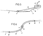
- FIGS 3 to 6 illustrate other modes of realization of the rotating head 5.
- the rotating head 5 has a central hub 11 to which two radial arms are attached opposite 12, delimiting two respective water passages 13 which feed two nozzles 6 carried respectively by the free ends of the two radial arms 12.
- the two nozzles 6 here emit two cutting jets of water 7, diametrically opposite and directed outward.
- the set of two radial arms 12 can be replaced by a disc (see also figure 1).
- the rotating head 5 shown in Figure 4 still has two radial arms 12, of conformation tubular with water passages 3, which bring to their free ends two nozzles 6.
- the two nozzles 6 are oriented so as to emit two jets cutting water 7 in tangential direction.
- Nozzles 6 are advantageously orientable, between an almost radial (figure 3) and a tangential position (figure 4), which makes it possible to act on the speed of rotation of the rotating head 5 and, most importantly, to expand or restrict the area of action of sharp water jets 7.
- Figure 5 shows another rotating head 5 in which the nozzle 6 (here unique) is carried by the end free of a rigid blade 17, which extends radially to from a hub 11 and which has a water passage internal (not shown) connected to the central inlet pressurized water.
- the water jet 7, emitted by the nozzle 6, cuts the vegetation and causes rotation of the head 5 about its axis 15. During this rotation, a cutting edge 18 of the blade 17 exerts an additional cutting action on the vegetation, inside the central circle which is not swept by the water jet 7.
- Figure 6 shows yet another head rotating 5, composed of a central hub 11 from from which extend in diametrically positions opposite, two flexible tubes 19 of small diameter, defining water passages connected to the inlet pressurized water plant.
- Free ends respective 20 of the two flexible tubes 19 constitute, by themselves, the two nozzles which emit the jets of cutting water 7.
- the flexible tubes 19 are behave, during their rotation, like cuts which complement the cutting action of the water jets 7. Note that in this embodiment, it is not no need to give specific guidance to end portions 20 constituting the emission nozzles of the sharp water jets; in fact, the flexible tubes 19 are behave like a garden hose left free, which starts spinning by itself when it emits a jet of water under pressure.
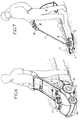
- Figure 7 shows the shape that can appear, in practical, a device according to the invention of simple and light design, supplied directly with water from outside, under sufficient pressure to smooth operation, by a flexible hose 21.
- the device looks like a portable device light with a handle 22, a handle formed by the tube 1 and the rotary head 5, the only control member necessary being a manual valve 23 for controlling the entry of water into the tube 1.
- FIG. 7 also illustrates the role of protective casing played by the deflector 16, vis-à-vis the user of the device.
- Figure 8 shows a machine mounted on 24 wheels, similar to a lawn mower, which carries a water tank 3 and a motor booster 4 thermal.
- the rotating head emitting one or more cutting water jets 7, is mounted under the machine.
- a large machine like this can have two heads rotating, parallel axes, including water jets respective create a "chisel" effect by crossing.
- Figure 9 shows a device according to the invention which is similar to that of FIG. 7, but which is used with an electric booster 10 from trade, placed on the ground.
- the booster 10 is supplied in water from outside via a flexible hose 21.
- Another flexible pipe 25 connects the booster 10 to the handle 22 of the device, and thus powers this device under sufficient pressure for proper operation.
- Figure 10 shows another device according to the invention, provided with a thermal booster 10 incorporated, supplied with water from outside by a flexible hose 21. To the extent that, due to the incorporation of booster 10, this is a relatively heavy portable device, this is provided a handlebar 8 and a strap 26 for carrying it "A shoulder strap”.
- the means of water supply, the means of water pressurization, details of shape and structure of the rotating head, and the number of nozzles carried by the rotating head, can be modified, remaining within the scope of the claims.
Landscapes
- Life Sciences & Earth Sciences (AREA)
- Environmental Sciences (AREA)
- Perforating, Stamping-Out Or Severing By Means Other Than Cutting (AREA)
- Fertilizers (AREA)
- Soil Working Implements (AREA)
- Shovels (AREA)
- Hydroponics (AREA)
Applications Claiming Priority (2)
| Application Number | Priority Date | Filing Date | Title |
|---|---|---|---|
| FR9709538 | 1997-07-22 | ||
| FR9709538A FR2766323B1 (fr) | 1997-07-22 | 1997-07-22 | Procede et dispositif pour la coupe de la vegetation |
Publications (2)
| Publication Number | Publication Date |
|---|---|
| EP0893047A1 true EP0893047A1 (de) | 1999-01-27 |
| EP0893047B1 EP0893047B1 (de) | 2002-05-02 |
Family
ID=9509677
Family Applications (1)
| Application Number | Title | Priority Date | Filing Date |
|---|---|---|---|
| EP98420124A Expired - Lifetime EP0893047B1 (de) | 1997-07-22 | 1998-07-20 | Verfahren und Vorrichtung zum Schneiden von Pflanzen |
Country Status (7)
| Country | Link |
|---|---|
| US (1) | US6256886B1 (de) |
| EP (1) | EP0893047B1 (de) |
| AT (1) | ATE216831T1 (de) |
| DE (1) | DE69805141T2 (de) |
| ES (1) | ES2176938T3 (de) |
| FR (1) | FR2766323B1 (de) |
| PT (1) | PT893047E (de) |
Cited By (2)
| Publication number | Priority date | Publication date | Assignee | Title |
|---|---|---|---|---|
| WO2002045478A1 (en) * | 2000-12-08 | 2002-06-13 | Mtd Products Inc | Water stream foliage cutter |
| ITUA20164575A1 (it) * | 2016-06-21 | 2017-12-21 | Giorgio Micheletti | Apparato per lo sfalcio di erba, erbacce o similari |
Families Citing this family (10)
| Publication number | Priority date | Publication date | Assignee | Title |
|---|---|---|---|---|
| US7281364B2 (en) * | 2003-08-14 | 2007-10-16 | Maconachy Frank J | Water-cutting harvesting apparatus and method therefor |
| US7350511B1 (en) | 2005-07-18 | 2008-04-01 | Walbro Engine Management, L.L.C. | Fuel vapor control system |
| DE102005056471A1 (de) * | 2005-11-26 | 2007-05-31 | Gerald Schmitt | Wasserstrahlschneidwerk zur Ernte landwirtschaftlicher Produkte |
| US7681385B2 (en) * | 2008-02-07 | 2010-03-23 | Degelman Industries Ltd. | Mower liquid herbicide applicator |
| US7900429B2 (en) * | 2008-02-07 | 2011-03-08 | Degelman Industries Ltd. | Liquid herbicide applicator drive shaft rotary seal |
| WO2013006921A1 (en) * | 2011-07-13 | 2013-01-17 | South Australian No-Till Farmers Association Inc. | Weed pruner |
| CN103406944A (zh) * | 2013-08-23 | 2013-11-27 | 昆山升东物资有限公司 | 一种自旋转水切割装置 |
| CN103433975A (zh) * | 2013-08-28 | 2013-12-11 | 昆山建金工业设计有限公司 | 一种水切割高速转动装置 |
| CN114982558A (zh) * | 2022-07-15 | 2022-09-02 | 内蒙古工业大学 | 一种用于草原改良的机械-水射流联合切根机 |
| US20250107482A1 (en) * | 2023-09-28 | 2025-04-03 | William E Clemons, JR. | Riding apparatus for mowing and pressure surface cleaning |
Citations (7)
| Publication number | Priority date | Publication date | Assignee | Title |
|---|---|---|---|---|
| FR2312953A1 (fr) * | 1975-06-07 | 1976-12-31 | Hoffmann Manfred | Appareil pour sectionner et pour defibrer des plantes et des elements de plantes |
| GB2093327A (en) * | 1981-02-21 | 1982-09-02 | Watts Derek James | High pressure liquid cutting means |
| DE3135927A1 (de) * | 1981-09-10 | 1983-03-24 | Klöckner-Humboldt-Deutz AG Zweigniederlassung Fahr, 7702 Gottmadingen | Verfahren und vorrichtung zum maehen von halmgut |
| US4499710A (en) * | 1984-02-09 | 1985-02-19 | Bolton John D | Jet power lawn mower |
| US5148992A (en) * | 1991-03-19 | 1992-09-22 | Textron Inc. | Washing accessory for a string trimmer |
| FR2677903A1 (fr) * | 1991-06-20 | 1992-12-24 | Delery Creations | Dispositif de nettoyage d'une surface par jets de liquide et organes rotatifs disposes a l'interieur d'un carter ou capot protecteur peripherique comportant un tel dispositif. |
| DE9300077U1 (de) * | 1993-01-06 | 1993-03-04 | Ehringfeld, Johann, 6663 Dellfeld | Vorrichtung zum Mähen von Gras- und Rasenflächen |
Family Cites Families (2)
| Publication number | Priority date | Publication date | Assignee | Title |
|---|---|---|---|---|
| US3090187A (en) * | 1960-12-05 | 1963-05-21 | Charles M Livingston | Liquid distributing mower blade |
| US5456412A (en) * | 1992-03-16 | 1995-10-10 | Agee; J. Christopher | High pressure surface washing device |
-
1997
- 1997-07-22 FR FR9709538A patent/FR2766323B1/fr not_active Expired - Fee Related
-
1998
- 1998-07-20 AT AT98420124T patent/ATE216831T1/de not_active IP Right Cessation
- 1998-07-20 DE DE69805141T patent/DE69805141T2/de not_active Expired - Lifetime
- 1998-07-20 EP EP98420124A patent/EP0893047B1/de not_active Expired - Lifetime
- 1998-07-20 PT PT98420124T patent/PT893047E/pt unknown
- 1998-07-20 ES ES98420124T patent/ES2176938T3/es not_active Expired - Lifetime
- 1998-07-21 US US09/120,364 patent/US6256886B1/en not_active Expired - Lifetime
Patent Citations (7)
| Publication number | Priority date | Publication date | Assignee | Title |
|---|---|---|---|---|
| FR2312953A1 (fr) * | 1975-06-07 | 1976-12-31 | Hoffmann Manfred | Appareil pour sectionner et pour defibrer des plantes et des elements de plantes |
| GB2093327A (en) * | 1981-02-21 | 1982-09-02 | Watts Derek James | High pressure liquid cutting means |
| DE3135927A1 (de) * | 1981-09-10 | 1983-03-24 | Klöckner-Humboldt-Deutz AG Zweigniederlassung Fahr, 7702 Gottmadingen | Verfahren und vorrichtung zum maehen von halmgut |
| US4499710A (en) * | 1984-02-09 | 1985-02-19 | Bolton John D | Jet power lawn mower |
| US5148992A (en) * | 1991-03-19 | 1992-09-22 | Textron Inc. | Washing accessory for a string trimmer |
| FR2677903A1 (fr) * | 1991-06-20 | 1992-12-24 | Delery Creations | Dispositif de nettoyage d'une surface par jets de liquide et organes rotatifs disposes a l'interieur d'un carter ou capot protecteur peripherique comportant un tel dispositif. |
| DE9300077U1 (de) * | 1993-01-06 | 1993-03-04 | Ehringfeld, Johann, 6663 Dellfeld | Vorrichtung zum Mähen von Gras- und Rasenflächen |
Cited By (4)
| Publication number | Priority date | Publication date | Assignee | Title |
|---|---|---|---|---|
| US6481193B2 (en) | 1999-12-09 | 2002-11-19 | Mtd Products Inc. | Water stream foliage cutter |
| WO2002045478A1 (en) * | 2000-12-08 | 2002-06-13 | Mtd Products Inc | Water stream foliage cutter |
| ITUA20164575A1 (it) * | 2016-06-21 | 2017-12-21 | Giorgio Micheletti | Apparato per lo sfalcio di erba, erbacce o similari |
| WO2017221150A1 (en) * | 2016-06-21 | 2017-12-28 | Giorgio Micheletti | Apparatus for mowing grass, weeds or the like |
Also Published As
| Publication number | Publication date |
|---|---|
| FR2766323B1 (fr) | 1999-09-17 |
| PT893047E (pt) | 2002-09-30 |
| FR2766323A1 (fr) | 1999-01-29 |
| EP0893047B1 (de) | 2002-05-02 |
| DE69805141D1 (de) | 2002-06-06 |
| US6256886B1 (en) | 2001-07-10 |
| ES2176938T3 (es) | 2002-12-01 |
| DE69805141T2 (de) | 2002-12-12 |
| ATE216831T1 (de) | 2002-05-15 |
Similar Documents
| Publication | Publication Date | Title |
|---|---|---|
| EP0893047B1 (de) | Verfahren und Vorrichtung zum Schneiden von Pflanzen | |
| EP0147344B1 (de) | Schneidapparat zur Verwendung in der Landwirtschaft, dem Weinbau und der Baumgärtnerei | |
| CA1335865C (fr) | Machines agricoles pour la recolte | |
| FR2464637A1 (fr) | Outil portatif a moteur et parties constitutives de cet outil | |
| FR2569940A1 (fr) | Faucheuse a moteur comportant un element de manoeuvre orientable | |
| FR2586054A1 (fr) | Appareil pour le nettoyage automatique notamment du fond d'une piscine | |
| EP0017519A2 (de) | Trockenstaubsauger für Bodenflächen | |
| FR2583258A1 (fr) | Faucheuse rotative | |
| FR2808964A1 (fr) | Effeuilleuse, plus specialement destinee a l'effeuillage selectif de la vigne | |
| FR2663189A1 (fr) | Machine de fenaison pour l'andainage, comportant au moins deux roues rateleuses. | |
| CA2253676C (fr) | Procede et dispositif pour la coupe de la vegetation | |
| FR2816165A1 (fr) | Machine de ramassage et de broyage de vegetaux | |
| FR2677903A1 (fr) | Dispositif de nettoyage d'une surface par jets de liquide et organes rotatifs disposes a l'interieur d'un carter ou capot protecteur peripherique comportant un tel dispositif. | |
| FR2571587A1 (fr) | Aspirateur a gazon | |
| EP0653157B1 (de) | Anordnung zum Fördern einer Luftströmung mit einer flachen Gestalt | |
| US6481193B2 (en) | Water stream foliage cutter | |
| EP2241171B1 (de) | Werkzeughalterungsvorrichtung zur Aufrechterhaltung der Werkzeuge in Arbeitsposition für adaptierbare Formen | |
| EP1539363B1 (de) | Vorrichtung zur zerstäubung einer flüssigkeit und landwirtschaftlische maschine mit mindenstens einer solchen vorrichtung | |
| FR2461780A1 (fr) | Tete de dragage pour drague suceuse | |
| FR2604858A1 (fr) | Appareil pour la coupe de vegetaux, notamment pour le debroussaillage et l'elagage | |
| WO2005029954A2 (fr) | Dispositif de desherbage et de binage mecanique | |
| EP0777959A1 (de) | Rasenkanten-Schneider | |
| FR2862483A1 (fr) | Dispositif d'effeuillage de plants, notamment de vignes, par buses alimentees en air comprime | |
| FR2631256A1 (fr) | Dispositif de brossage du plan de joint d'un trou d'homme prevu pour l'acces a l'interieur d'une cuve | |
| FR2737384A1 (fr) | Carter de debroussailleuse |
Legal Events
| Date | Code | Title | Description |
|---|---|---|---|
| PUAI | Public reference made under article 153(3) epc to a published international application that has entered the european phase |
Free format text: ORIGINAL CODE: 0009012 |
|
| AK | Designated contracting states |
Kind code of ref document: A1 Designated state(s): AT BE CH DE DK ES FI FR GB IT LI NL PT SE |
|
| AX | Request for extension of the european patent |
Free format text: AL;LT;LV;MK;RO;SI |
|
| 17P | Request for examination filed |
Effective date: 19990215 |
|
| AKX | Designation fees paid |
Free format text: AT BE CH DE DK ES FI FR GB IT LI NL PT SE |
|
| GRAG | Despatch of communication of intention to grant |
Free format text: ORIGINAL CODE: EPIDOS AGRA |
|
| GRAG | Despatch of communication of intention to grant |
Free format text: ORIGINAL CODE: EPIDOS AGRA |
|
| GRAH | Despatch of communication of intention to grant a patent |
Free format text: ORIGINAL CODE: EPIDOS IGRA |
|
| 17Q | First examination report despatched |
Effective date: 20010827 |
|
| RAP1 | Party data changed (applicant data changed or rights of an application transferred) |
Owner name: SPEED FRANCE |
|
| REG | Reference to a national code |
Ref country code: GB Ref legal event code: IF02 |
|
| GRAH | Despatch of communication of intention to grant a patent |
Free format text: ORIGINAL CODE: EPIDOS IGRA |
|
| GRAA | (expected) grant |
Free format text: ORIGINAL CODE: 0009210 |
|
| AK | Designated contracting states |
Kind code of ref document: B1 Designated state(s): AT BE CH DE DK ES FI FR GB IT LI NL PT SE |
|
| PG25 | Lapsed in a contracting state [announced via postgrant information from national office to epo] |
Ref country code: NL Free format text: LAPSE BECAUSE OF FAILURE TO SUBMIT A TRANSLATION OF THE DESCRIPTION OR TO PAY THE FEE WITHIN THE PRESCRIBED TIME-LIMIT Effective date: 20020502 Ref country code: FI Free format text: LAPSE BECAUSE OF FAILURE TO SUBMIT A TRANSLATION OF THE DESCRIPTION OR TO PAY THE FEE WITHIN THE PRESCRIBED TIME-LIMIT Effective date: 20020502 Ref country code: AT Free format text: LAPSE BECAUSE OF FAILURE TO SUBMIT A TRANSLATION OF THE DESCRIPTION OR TO PAY THE FEE WITHIN THE PRESCRIBED TIME-LIMIT Effective date: 20020502 |
|
| REF | Corresponds to: |
Ref document number: 216831 Country of ref document: AT Date of ref document: 20020515 Kind code of ref document: T |
|
| REG | Reference to a national code |
Ref country code: GB Ref legal event code: FG4D Free format text: NOT ENGLISH |
|
| REG | Reference to a national code |
Ref country code: CH Ref legal event code: EP |
|
| REF | Corresponds to: |
Ref document number: 69805141 Country of ref document: DE Date of ref document: 20020606 |
|
| PG25 | Lapsed in a contracting state [announced via postgrant information from national office to epo] |
Ref country code: LI Free format text: LAPSE BECAUSE OF NON-PAYMENT OF DUE FEES Effective date: 20020731 Ref country code: CH Free format text: LAPSE BECAUSE OF NON-PAYMENT OF DUE FEES Effective date: 20020731 |
|
| PG25 | Lapsed in a contracting state [announced via postgrant information from national office to epo] |
Ref country code: DK Free format text: LAPSE BECAUSE OF FAILURE TO SUBMIT A TRANSLATION OF THE DESCRIPTION OR TO PAY THE FEE WITHIN THE PRESCRIBED TIME-LIMIT Effective date: 20020802 |
|
| GBT | Gb: translation of ep patent filed (gb section 77(6)(a)/1977) |
Effective date: 20020726 |
|
| REG | Reference to a national code |
Ref country code: PT Ref legal event code: SC4A Free format text: AVAILABILITY OF NATIONAL TRANSLATION Effective date: 20020626 |
|
| NLV1 | Nl: lapsed or annulled due to failure to fulfill the requirements of art. 29p and 29m of the patents act | ||
| REG | Reference to a national code |
Ref country code: ES Ref legal event code: FG2A Ref document number: 2176938 Country of ref document: ES Kind code of ref document: T3 |
|
| PLBE | No opposition filed within time limit |
Free format text: ORIGINAL CODE: 0009261 |
|
| STAA | Information on the status of an ep patent application or granted ep patent |
Free format text: STATUS: NO OPPOSITION FILED WITHIN TIME LIMIT |
|
| REG | Reference to a national code |
Ref country code: CH Ref legal event code: PL |
|
| 26N | No opposition filed |
Effective date: 20030204 |
|
| PGFP | Annual fee paid to national office [announced via postgrant information from national office to epo] |
Ref country code: SE Payment date: 20050714 Year of fee payment: 8 |
|
| PGFP | Annual fee paid to national office [announced via postgrant information from national office to epo] |
Ref country code: FR Payment date: 20050718 Year of fee payment: 8 |
|
| PGFP | Annual fee paid to national office [announced via postgrant information from national office to epo] |
Ref country code: PT Payment date: 20050720 Year of fee payment: 8 |
|
| PGFP | Annual fee paid to national office [announced via postgrant information from national office to epo] |
Ref country code: BE Payment date: 20050913 Year of fee payment: 8 |
|
| PG25 | Lapsed in a contracting state [announced via postgrant information from national office to epo] |
Ref country code: SE Free format text: LAPSE BECAUSE OF NON-PAYMENT OF DUE FEES Effective date: 20060721 |
|
| PG25 | Lapsed in a contracting state [announced via postgrant information from national office to epo] |
Ref country code: BE Free format text: LAPSE BECAUSE OF NON-PAYMENT OF DUE FEES Effective date: 20060731 |
|
| PG25 | Lapsed in a contracting state [announced via postgrant information from national office to epo] |
Ref country code: PT Free format text: LAPSE BECAUSE OF NON-PAYMENT OF DUE FEES Effective date: 20070122 |
|
| REG | Reference to a national code |
Ref country code: PT Ref legal event code: MM4A Free format text: LAPSE DUE TO NON-PAYMENT OF FEES Effective date: 20070122 |
|
| EUG | Se: european patent has lapsed | ||
| REG | Reference to a national code |
Ref country code: FR Ref legal event code: ST Effective date: 20070330 |
|
| BERE | Be: lapsed |
Owner name: *SPEED FRANCE Effective date: 20060731 |
|
| PG25 | Lapsed in a contracting state [announced via postgrant information from national office to epo] |
Ref country code: FR Free format text: LAPSE BECAUSE OF NON-PAYMENT OF DUE FEES Effective date: 20060731 |
|
| PGFP | Annual fee paid to national office [announced via postgrant information from national office to epo] |
Ref country code: IT Payment date: 20170712 Year of fee payment: 20 Ref country code: ES Payment date: 20170809 Year of fee payment: 20 Ref country code: DE Payment date: 20170713 Year of fee payment: 20 Ref country code: GB Payment date: 20170721 Year of fee payment: 20 |
|
| REG | Reference to a national code |
Ref country code: DE Ref legal event code: R071 Ref document number: 69805141 Country of ref document: DE |
|
| REG | Reference to a national code |
Ref country code: GB Ref legal event code: PE20 Expiry date: 20180719 |
|
| PG25 | Lapsed in a contracting state [announced via postgrant information from national office to epo] |
Ref country code: GB Free format text: LAPSE BECAUSE OF EXPIRATION OF PROTECTION Effective date: 20180719 |
|
| REG | Reference to a national code |
Ref country code: ES Ref legal event code: FD2A Effective date: 20201204 |
|
| PG25 | Lapsed in a contracting state [announced via postgrant information from national office to epo] |
Ref country code: ES Free format text: LAPSE BECAUSE OF EXPIRATION OF PROTECTION Effective date: 20180721 |