EP0893185B1 - Foret hélicoidal - Google Patents
Foret hélicoidal Download PDFInfo
- Publication number
- EP0893185B1 EP0893185B1 EP98304288A EP98304288A EP0893185B1 EP 0893185 B1 EP0893185 B1 EP 0893185B1 EP 98304288 A EP98304288 A EP 98304288A EP 98304288 A EP98304288 A EP 98304288A EP 0893185 B1 EP0893185 B1 EP 0893185B1
- Authority
- EP
- European Patent Office
- Prior art keywords
- drill bit
- bit
- flute
- predetermined
- angle
- Prior art date
- Legal status (The legal status is an assumption and is not a legal conclusion. Google has not performed a legal analysis and makes no representation as to the accuracy of the status listed.)
- Expired - Lifetime
Links
- 238000000034 method Methods 0.000 claims abstract description 14
- 230000008569 process Effects 0.000 claims abstract description 14
- 239000000463 material Substances 0.000 claims description 2
- 230000004323 axial length Effects 0.000 claims 2
- 238000005553 drilling Methods 0.000 description 18
- 239000002023 wood Substances 0.000 description 14
- 239000002184 metal Substances 0.000 description 13
- 230000008901 benefit Effects 0.000 description 3
- 230000004048 modification Effects 0.000 description 2
- 238000012986 modification Methods 0.000 description 2
- 230000003763 resistance to breakage Effects 0.000 description 2
- 229910000831 Steel Inorganic materials 0.000 description 1
- 230000003466 anti-cipated effect Effects 0.000 description 1
- 230000008859 change Effects 0.000 description 1
- 238000010276 construction Methods 0.000 description 1
- 230000003247 decreasing effect Effects 0.000 description 1
- 230000003292 diminished effect Effects 0.000 description 1
- 230000003467 diminishing effect Effects 0.000 description 1
- 238000005516 engineering process Methods 0.000 description 1
- 239000002648 laminated material Substances 0.000 description 1
- 238000004519 manufacturing process Methods 0.000 description 1
- 239000010959 steel Substances 0.000 description 1
Images


Classifications
-
- B—PERFORMING OPERATIONS; TRANSPORTING
- B23—MACHINE TOOLS; METAL-WORKING NOT OTHERWISE PROVIDED FOR
- B23B—TURNING; BORING
- B23B51/00—Tools for drilling machines
- B23B51/02—Twist drills
-
- B—PERFORMING OPERATIONS; TRANSPORTING
- B24—GRINDING; POLISHING
- B24B—MACHINES, DEVICES, OR PROCESSES FOR GRINDING OR POLISHING; DRESSING OR CONDITIONING OF ABRADING SURFACES; FEEDING OF GRINDING, POLISHING, OR LAPPING AGENTS
- B24B1/00—Processes of grinding or polishing; Use of auxiliary equipment in connection with such processes
-
- B—PERFORMING OPERATIONS; TRANSPORTING
- B24—GRINDING; POLISHING
- B24B—MACHINES, DEVICES, OR PROCESSES FOR GRINDING OR POLISHING; DRESSING OR CONDITIONING OF ABRADING SURFACES; FEEDING OF GRINDING, POLISHING, OR LAPPING AGENTS
- B24B19/00—Single-purpose machines or devices for particular grinding operations not covered by any other main group
- B24B19/02—Single-purpose machines or devices for particular grinding operations not covered by any other main group for grinding grooves, e.g. on shafts, in casings, in tubes, homokinetic joint elements
- B24B19/04—Single-purpose machines or devices for particular grinding operations not covered by any other main group for grinding grooves, e.g. on shafts, in casings, in tubes, homokinetic joint elements for fluting drill shanks
-
- B—PERFORMING OPERATIONS; TRANSPORTING
- B23—MACHINE TOOLS; METAL-WORKING NOT OTHERWISE PROVIDED FOR
- B23B—TURNING; BORING
- B23B2251/00—Details of tools for drilling machines
- B23B2251/18—Configuration of the drill point
-
- B—PERFORMING OPERATIONS; TRANSPORTING
- B23—MACHINE TOOLS; METAL-WORKING NOT OTHERWISE PROVIDED FOR
- B23B—TURNING; BORING
- B23B2251/00—Details of tools for drilling machines
- B23B2251/40—Flutes, i.e. chip conveying grooves
- B23B2251/404—Flutes, i.e. chip conveying grooves with decreasing depth in a direction towards the shank from the tool tip
-
- B—PERFORMING OPERATIONS; TRANSPORTING
- B23—MACHINE TOOLS; METAL-WORKING NOT OTHERWISE PROVIDED FOR
- B23B—TURNING; BORING
- B23B2251/00—Details of tools for drilling machines
- B23B2251/60—Drills with pilots
-
- Y—GENERAL TAGGING OF NEW TECHNOLOGICAL DEVELOPMENTS; GENERAL TAGGING OF CROSS-SECTIONAL TECHNOLOGIES SPANNING OVER SEVERAL SECTIONS OF THE IPC; TECHNICAL SUBJECTS COVERED BY FORMER USPC CROSS-REFERENCE ART COLLECTIONS [XRACs] AND DIGESTS
- Y10—TECHNICAL SUBJECTS COVERED BY FORMER USPC
- Y10T—TECHNICAL SUBJECTS COVERED BY FORMER US CLASSIFICATION
- Y10T408/00—Cutting by use of rotating axially moving tool
- Y10T408/89—Tool or Tool with support
- Y10T408/905—Having stepped cutting edges
- Y10T408/906—Axially spaced
-
- Y—GENERAL TAGGING OF NEW TECHNOLOGICAL DEVELOPMENTS; GENERAL TAGGING OF CROSS-SECTIONAL TECHNOLOGIES SPANNING OVER SEVERAL SECTIONS OF THE IPC; TECHNICAL SUBJECTS COVERED BY FORMER USPC CROSS-REFERENCE ART COLLECTIONS [XRACs] AND DIGESTS
- Y10—TECHNICAL SUBJECTS COVERED BY FORMER USPC
- Y10T—TECHNICAL SUBJECTS COVERED BY FORMER US CLASSIFICATION
- Y10T408/00—Cutting by use of rotating axially moving tool
- Y10T408/89—Tool or Tool with support
- Y10T408/907—Tool or Tool with support including detailed shank
-
- Y—GENERAL TAGGING OF NEW TECHNOLOGICAL DEVELOPMENTS; GENERAL TAGGING OF CROSS-SECTIONAL TECHNOLOGIES SPANNING OVER SEVERAL SECTIONS OF THE IPC; TECHNICAL SUBJECTS COVERED BY FORMER USPC CROSS-REFERENCE ART COLLECTIONS [XRACs] AND DIGESTS
- Y10—TECHNICAL SUBJECTS COVERED BY FORMER USPC
- Y10T—TECHNICAL SUBJECTS COVERED BY FORMER US CLASSIFICATION
- Y10T408/00—Cutting by use of rotating axially moving tool
- Y10T408/89—Tool or Tool with support
- Y10T408/909—Having peripherally spaced cutting edges
- Y10T408/9095—Having peripherally spaced cutting edges with axially extending relief channel
-
- Y—GENERAL TAGGING OF NEW TECHNOLOGICAL DEVELOPMENTS; GENERAL TAGGING OF CROSS-SECTIONAL TECHNOLOGIES SPANNING OVER SEVERAL SECTIONS OF THE IPC; TECHNICAL SUBJECTS COVERED BY FORMER USPC CROSS-REFERENCE ART COLLECTIONS [XRACs] AND DIGESTS
- Y10—TECHNICAL SUBJECTS COVERED BY FORMER USPC
- Y10T—TECHNICAL SUBJECTS COVERED BY FORMER US CLASSIFICATION
- Y10T408/00—Cutting by use of rotating axially moving tool
- Y10T408/89—Tool or Tool with support
- Y10T408/909—Having peripherally spaced cutting edges
- Y10T408/9095—Having peripherally spaced cutting edges with axially extending relief channel
- Y10T408/9097—Spiral channel
Definitions
- the invention relates to twist drill bits having flutes that extend from a tip of the drill bit to a termination point on the shank of the bit.
- the drill bit flutes define a web thickness which increases along the length of the flute from the tip to the termination point.
- Conventional drill bits employ a web taper rate that is recommended by various Standards in the industry.
- the Assignee of the present invention has been selling conventional drill bits according to the preamble of claim 1, which track the Standards and have conventional web thickness taper rates between 0.024 to 0.030 centimetres per centimetre (or inches per inch). Also, it has been selling a self-centering drill bit with pilot tip under the BULLET® trademark and having a web taper rate of about 0.027 centimetres per centimetre (inches per inch) of flute length.
- This self-centering drill bit was designed with the end user who uses a portable drill in mind, particularly one who desires a bit which is optimised to drill in both metal and wood.
- the first versions of these bits are disclosed in U.S. Patent Nos. 4,968,193, issued November 6, 1990, to Chaconas et al., and 5,288,183, issued February 22, 1994, to Chaconas et al., each of which is assigned to the same Assignee of the present invention.
- a twist drill bit comprising:
- a twist drill bit having a web thickness taper rate over the length of the flute which is about twice as great as the web taper rate of conventional drill bits, thereby providing significantly increased resistance to breakage while drilling in metal, yet, for drill bits having nominal diameters of 0.0635 cm (0.0250 inches) or greater, enabling the user to drill holes in 3.81 cm (inch and one-half) thick wood in one pass.
- bits employing the present invention experience significantly enhanced toughness and resistance to breakage, particularly when used by an operator of a portable drill.
- a feature by which the above objects may be attained is by forming the flutes with the web taper rate of the present invention along a flute length which is less than the flute length specified for a predetermined bit nominal diameter by the ASME B94.11-M-1993 Standard, and specifically by reducing the flute length by about 0.762 cm to about 1.778 cm (0.3 inch to about 0.7 inch). Optimally, the flute length is reduced by about 1.27 cm (one-half inch), for all nominal diameters of the drill bits.
- a preferred feature is to form such indicia as the nominal size of the bit in the marking zone, so that in the engagement by the chuck of the bit shank does not erase the indicia.
- a process for making a twist drill bit having a tip, a shank and two flutes defining a predetermined web thickness at the tip comprising:
- Another feature by which the above objects can be attained is by causing relative axial movement between a grinding wheel and drill bits stock while rotating the drill bit stock about its axis to grind the flute having the desired flute length with the web thickness taper rate of the present invention and retracting the grinding wheel from the drill bit stock upon reaching a point which is a predetermined distance before the point at which the flute would terminate at the shank if the taper rate were maintained.
- One feature by which the above object can be attained is by optionally providing the drill bit tip portion with a fishtail angle of less than 180°.
- Yet another preferred feature is to form a chamfer adjacent the fishtail such that a cutting edge on the chamfer connects a cutting lip on the fishtail with the outer diameter of the drill bit.
- Still another preferred feature is to provide the pilot portion with a back taper in the axial direction.
- Still another preferred feature is to provide a back taper which is negative, and at least 1° negative.
- Yet another feature is to size the width or diameter of the pilot portion to be about one-half the nominal bit diameter.
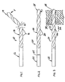
- a conventional twist drill bit is shown generally as 10, and includes a shank portion 12, a flute portion 14 containing two flutes 16 and a tip portion 18.
- the drill bit encounters greater than normal forces F transverse to the axis of the drill bit, as shown schematically in Figure 1. If the force F is great enough, the drill bit will break or fail as shown at 15. Tests run on a quarter inch (0.635 cm) diameter conventional twist drill bit found that the failure 15 occurred primarily in the fluted portion 14, when the bit was subjected to a peak force at failure in the range from 68.04 to 79.38 kg (150 to 175 lbs).
- a twist drill using the taper rate of the present invention is shown generally as 20 in Figure 2, and includes shank portion 22, flute portion 24 having two flutes 26 and a tip portion 28.
- shank portion 22 includes shank portion 22 and flute portion 24 having two flutes 26 and a tip portion 28.
- flute portion 24 having two flutes 26 and a tip portion 28.
- Figure 3 shows an alternate embodiment of a twist drill incorporating the web thickness taper rate of the present invention, and illustrating its ability to perform well in wood while maintaining its much enhanced strength while drilling in metal. It has been found that a twist drill bit made according to the invention shown in Figure 3 and having a nominal bit diameter of 1/4" (0.635 cm) can be used to drill a hole through a 2.54 to 3.81 cm (1-1/2") thick piece of wood without having to withdraw the bit to clear the sawdust from the flutes and then reinserting the bit to finish the hole.
- the wood is shown at 30 and is a two by four (5.08 cm by 10.16 cm) for example.
- the present invention as embodied in the twist drill bit shown in Figure 3 reduces the amount of "woodpeckering" that the user must do to drill holes in wood.
- the operator can use a metal-drilling drill bit to drill a hole through the board in one pass, as indicated by arrow 32.
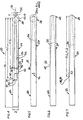
- the web taper rates of the present invention are shown in various embodiments in Figures 4 through 7.
- Figure 4 schematically illustrates the web taper (shown in short dashes) of the present invention superimposed upon the web taper (shown as long and short dashes).
- the profile of the conventional web taper is referred to as 34, and the web profile of the present invention is referred to as 36.
- the improvements of the present invention affected are particularly effective when used in the environment of a drill bit designed for both metal-drilling and wood-drilling, by means of a hand-held power drill, where the operator can place more transverse stresses on the drill bit than, for example, the operator of a fixture drill bit such as one driven by a drill press.
- the most common drill bit used by the person operating a hand-held power drill is the foundation upon which the improvements of the present invention have been made. This is known as the "Jobber's-length drill bit" specifications for which are common in the industry and are set out in such Standards as the ASME B94.11 M-1993 and the NAS 907.
- the NAS 907 Standard specifies that the web taper rate for Types "A", “B” and “J" straight shank, jobber's length drill bits be a uniform taper of 0.017", 0.024" and 0.006" (0.0432 cm, 0.061 cm and 0.0152 cm), respectively, with respective tolerances of plus or minus 0.003" (0.0076 cm) plus or minus 0.003" (0.0076 cm), plus or minus 0.002" (0.0051 cm), respectively.
- the taper rates of the bits sold by the Assignee of the present invention track the Standards closely.
- the drill bits sold under the DeWALT® trademark have a taper rate of 0.024" (0.061 cm) for drill bit nominal diameters up to and including 3/16" (0.476 cm) and a web taper rate of 0.030 inches per inch or centimetres per centimetre of flute length for drill bits having nominal diameters greater than 3/16 of an inch (0.476 cm).
- Self-centering drill bits having pilot tips sold under the BULLET® trademark have a web taper rate of 0.027 inches per inch (or centimetre per centimetre) of flute length.
- the results of the web taper rate recommended by the Standards and in common use are reflected in a deep flute, exiting the flute portion 24 at a termination point 38 with the outer diameter of the shank portion 22, the shank portion being defined as the portion of the drill bit outside of the portion that contains the flute and which is inserted in the chuck of a power drill.
- the web thickness of the conventional web profile 34 has increased from a thickness T to a thickness designated by 40, leaving a large flute depth 42 for receiving the chips or sawdust. This is in marked contrast to the geometry of the flute defining a web having a taper rate of the present invention.
- the web taper profile 36 exits the bit at a flute termination point 44.
- a uniform web taper rate of 0.068 inch per inch (or centimetre per centimetre) of flute length was selected and the resulting bit durability and performance far exceeded expectations.
- the transverse force F applied to a rotating drill bit cantilever-mounted drill bit exceeded 113.4 kg (250 lbs) (for a 1/4" (0.635 cm) nominal diameter drill bit), with very acceptable chip removal characteristics when drilling in metal.
- the web thickness taper rate was set at 0.054 inches per inch (or centimetres per centimetre) of flute length (plus or minus 0.003 inches (0.0076 cm)) for all sizes of drill bits from 1/8" (0.3175 cm) nominal diameter to 1/2" (1.27 cm) nominal diameter.
- the drill bit of this second embodiment maintain a failure at peak force of 113.4 to 136.08 kg (250 to 300 lbs) for a drill bit with a 1/4" (0.635 cm) nominal diameter, but it exhibited anti-woodpeckering characteristics when drilling wood. It was able to drill a hole in 1/2" (1.27 cm) thick wood (such as a 2 X 4) (5.08 x 10.16 cm) in one pass. Thus a drill bit was discovered that was much stronger than conventional drill bits when drilling in metal, yet be versatile enough to reduce the need for woodpeckering when drilling in wood.
- the preferred web thickness taper rate ranges from about 0.050 to about 0.071 inches per inch (centimetres per centimetre) of flute length, and the flute length FL lies in the range from about 0.762 cm to about 1.778 cm (0.3 inch to about 0.7 inch) less than the flute length specified where a particular fray drill bit having a particular nominal bit diameter, by the ASME Standard.
- the web taper rate of the present invention is anticipated to do well in a drill bit having a conventional chisel point or web-thinned point (such as a split point) as schematically shown in Figure 6, it is particularly useful in the metal/wood-drilling self-centering drill bit with pilot tip, developed by the Assignee of the present invention.
- These embodiments are shown in Figures 4 and 5, which in turn can be equipped with any of the tip portions 28 shown in Figures 9 through 13.
- the parameter nomenclature for these embodiments are noted in Figure 9, where the tip portion 28 includes a fishtail portion 56 and a pilot portion 58 extending axially outwardly from the fishtail portion.
- the fishtail portion includes fishtail cutting lips 62 arranged at a fishtail angle 60°.
- the cutting lips extend from the pilot portion to the outer diameter of the drill bit.
- the pilot portion 58 extends a distance "L” from the fishtail portion 56, and has a diameter "d” smaller than the nominal diameter "D" of the drill bit.
- the pilot portion defines an angular pilot wall 64 which is both radially and axially relieved as taught in the above-identified Chaconas et al. patents.
- the pilot portion 58 is formed with pilot cutting lips arranged at a point angle 68 and, in the preferred embodiment, defines a split point 66.
- the pilot portion is joined to the fishtail portion 56 with a radially-relieved fillet 70 having a radius "R".
- the geometry of the tip portion 28 is that contained in the bit presently on the market.
- the fishtail angle 60 is greater than 180°, namely is about 190°, and the orientation of the pilot wall defines an axial back taper 65 of about 5°.
- the convention used for the balance of this detailed description of the preferred embodiments is that a back taper on the pilot 58 which is directed radially inwardly from the tip end 66 of the bit 20 toward the fishtail portion 56 will be considered a "positive" angle, whereas a back taper which is directed radially outwardly, as identified as 67 in Figure 13 will be considered a "negative” back taper angle.
- a negligible back taper angle is shown as 69 in the embodiment shown in Figure 12.
- "negligible" means in the range from less than minus 1° to less than positive 1°.
- the fishtail portion 56 will exhibit increased longevity, if the fishtail angle 60 is reduced to lie in the range from about 168° to about 182°, and preferably about 170°. It has also been discovered that the pilot portion will exhibit increased longevity if its diameter "d" is approximately one-half the nominal bit diameter.
- the chamfer portion 72 includes at least one chamfer 74, and in the preferred embodiment includes two chamfers.
- the chamfers 74 are oriented at a chamfer angle 76 which is in the range of 75° to about 140° and is preferably about 90°.
- the chamfer angle 78 is about 45°, or one-half the two-chamfer included angle 76.
- the length of the chamfer 80 is from about 5% to about 15% of the nominal diameter and is preferably about 10% (is preferably about 0.0635 cm (0.025 inches)).
- the included angle 68 remains at about 135°, but the preferred back taper angle is in the range from 0° to 5.5°, with the preferred angle being 5°.
- the process for generating the pilot portion 58, the fishtail portion 56 and the radially-relieved fillet 70 is shown.
- the area of the pilot diameter relief is shown as 82; the fillet relief area is shown at 84, and the area of fishtail cutting lips relief is shown as 86.
- a continuous cutting edge is created by the fishtail cutting lips 62, fillet 70 and pilot wall cutting edge 65. In order to enable these edges to cut satisfactory, they all must be provided with relief surfaces as shown in Figure 15.
- a grinding wheel 88 having a grinding wheel face 90 and the bit axis 54 are oriented relative to one another such that the fishtail angle 60 divided by 2 is in the desired range.
- the pilot back taper angle 65 (positive or negative) is achieved by providing the grinding wheel 88 with a predetermined form, which also defines the shape of the fillet 70. To generate the desired edges and surfaces, the bit is positioned in the desired angular relationship to the grinding wheel 88 and is rotated about its axis 54 in the direction shown by arrow 92 and at the same time is moved into the wheel in the direction shown by arrow 94, thereby achieving the relief for the cutting edge formed by the pilot edge 65 fillet 70 and fishtail cutting lip 62. The process is repeated on the opposite side of the bit to generate both sets of cutting edges and reliefs.
- a grinding wheel 98 is positioned at a predetermined angle relative to the axis 54 of drill bit 20 and is brought into contact with the bit at the tip portion 28, or starting point of the flute and is moved radially inwardly to that position as shown by arrow 100.
- the bit stock 20 and the grinding wheel 98 are then caused to move relative to one another along an axial direction 102.
- the grinding wheel is held for a movement only in the radially inward and outward directions as shown by arrows 100.
- the bit stock is moved axially into the grinding wheel.
- a cam then causes the grinding wheel 98 to move radially outwardly as shown, thereby creating a desired web taper rate.
- the combination of the taper angle would create a variation in tolerance of the flute length FL1 of unacceptable breadth of variability as shown at 106.
- the flute length is a very important parameter in the manufacturer of twist drill bits, it is preferable to maintain a variation in flute lengths 108 to a plus or minus 0.318 cm (1/8"), namely 0.635 cm (1/4") in breadth.
- the process is completed when a second flute is formed diametrically opposite the flute just described using the same process.
- the process forms a modified parabolic flute.
- the web thickness taper rate of the present invention is believed to significantly improve the strength of drill bits having conventional point geometry, as schematically shown in Figure 6, it has particular impact upon the durability of drill bits having configurations of the tip portions 28 shown in Figures 9 through 13.
- the coaction of the taper rate, pilot width, back taper angle, and chamfer of the embodiment shown in Figures 11, will produce a twist drill bit having significantly improved strength in the flute and in the tip portions when drilling in metal, yet enables the user to drill holes in wood with a minimum of woodpeckering, attributes that are particularly desirable in drill bits for use by someone using a power drill, both metal and wood.
Landscapes
- Engineering & Computer Science (AREA)
- Mechanical Engineering (AREA)
- Drilling Tools (AREA)
- Acyclic And Carbocyclic Compounds In Medicinal Compositions (AREA)
Claims (34)
- Foret hélicoïdal, comprenant :une partie de tige, une partie filetée et une partie de pointe adjacente à la partie filetée ;la partie filetée définissant au moins un filet s'étendant depuis la partie de pointe et se terminant à la partie de tige, l'au moins un filet ayant une longueur prédéterminée de filet ;la partie filetée définissant, en outre, une âme ;l'âme, au voisinage de la partie de pointe, ayant une épaisseur d'âme prédéterminée ;caractérisé en ce que l'épaisseur de l'âme augmente depuis la partie de pointe jusqu'à la partie de tige, suivant un angle de conicité uniforme, dans la gamme de 0,050 à 0,071 cm par cm de longueur de filet.
- Foret selon la revendication 1, dans lequel la partie filetée définit deux filets s'étendant depuis la partie de pointe et se terminant à la partie de tige, ces filets ayant une longueur prédéterminée de filet.
- Foret selon l'une ou l'autre des revendications précédentes, dans lequel le foret a un diamètre nominal prédéterminé et dans lequel la longueur de filet est comprise dans la gamme d'environ 0,762 cm à environ 1,778 cm de moins que la longueur de filet spécifiée pour ledit diamètre prédéterminée par la norme ASME B94.11-M-1993.
- Foret selon la revendication 3, dans lequel la longueur de filet fait approximativement 1,27 cm de moins que la longueur de filet spécifiée pour ledit diamètre prédéterminé par la norme ASME B94.11-M-1993.
- Foret selon une quelconque des revendications précédentes, comprenant, en outre, une zone de repérage de foret sur la partie de tige, adjacente à la terminaison desdits filets, la longueur axiale de la zone de repérage de foret étant dans la gamme d'environ 0,762 cm à environ 1,778 cm, le foret étant repéré dans ladite zone de repérage de foret par des repères prédéterminés.
- Foret selon la revendication 5, comprenant, en outre, une zone de repérage de foret sur la partie de tige, adjacente à la terminaison desdits filets, la longueur axiale de la zone de repérage de foret faisant approximativement 1,27 cm, le foret étant repéré dans ladite zone de repérage de foret par des repères prédéterminés.
- Foret selon une quelconque des revendications précédentes, dans lequel :la partie de pointe comporte une partie en V et une partie de guidage s'étendant axialement vers l'extérieur depuis la partie en V, dans la direction opposée à la partie de tige ;la partie en V ayant un diamètre prédéterminé et des lèvres de coupe disposées suivant un angle en V prédéterminé ; etla partie de guidage ayant un diamètre prédéterminé inférieur au diamètre de la partie en V.
- Foret selon la revendication 7, dans lequel la partie de guidage définit une surface extérieure ayant une conicité arrière s'étendant vers la partie en V dans une direction axiale à un angle de conicité arrière prédéterminé.
- Foret selon l'une ou l'autre de la revendication 7 ou de la revendication 8, dans lequel ledit angle en V est inférieur ou égal à 180 °.
- Foret selon la revendication 9, dans lequel ledit angle en V est compris dans la gamme d'environ 168 ° à environ 178 °.
- Foret selon la revendication 10, dans lequel ledit angle en V est d'environ 170 °.
- Foret selon la revendication 8, dans lequel ledit angle de conicité arrière est positif.
- Foret selon une quelconque des revendications 8 à 12, dans lequel ledit angle de conicité arrière est compris dans la gamme d'environ 1 ° à environ 5,5 °.
- Foret selon la revendication 13, dans lequel ledit angle de conicité arrière est d'environ 5 °.
- Foret selon la revendication 8, dans lequel ledit angle de conicité arrière est d'au moins 1 ° négatif.
- Foret selon la revendication 8, dans lequel ledit angle de conicité arrière est négligeable.
- Foret selon une quelconque des revendications 7 à 16, dans lequel ladite partie de guidage définit des lèvres de coupe de guidage ménagées en un point d'amincissement de l'âme.
- Foret selon une quelconque des revendications 7 à 17, dans lequel ladite partie de guidage définit un point de séparation.
- Foret selon une quelconque des revendications 7 à 18, dans lequel ladite partie en V comporte, en outre, une partie chanfreinée.
- Foret selon la revendication 19, dans lequel la partie chanfreinée est adjacente auxdites lèvres de coupe et a un chanfrein s'étendant suivant un angle de chanfrein prédéterminé par rapport à l'axe dudit foret radialement vers l'extérieur depuis au moins une desdites lèvres de coupe et dans une direction axiale vers ladite partie de tige.
- Foret selon la revendication 20, dans lequel un chanfrein relie chaque lèvre de coupe au diamètre extérieur du foret.
- Foret selon la revendication 21, ayant deux chanfreins, lesdits deux chanfreins définissant un angle inclus de chanfrein dans la gamme de 75 à 140 °.
- Foret selon la revendication 22, dans lequel l'angle inclus de chanfrein est d'environ 90 °.
- Foret selon la revendication 20, dans lequel l'angle de chanfrein fait environ 45 °.
- Foret selon une quelconque des revendications 7 à 24, dans lequel le diamètre de la partie de guidage est compris dans la gamme d'environ 38 % à environ 52 % du diamètre nominal du foret.
- Foret selon une quelconque des revendications 7 à 25, dans lequel le diamètre de la partie de guidage fait approximativement la moitié du diamètre nominal du foret.
- Foret selon une quelconque des revendications précédentes, dans lequel le foret est un foret à tige droite de longueur Jobber.
- Foret selon une quelconque des revendications précédentes, dans lequel les filets sont paraboliques.
- Foret selon une quelconque des revendications précédentes, dans lequel le filet se termine à la tige en une partie de rayon.
- Procédé de fabrication d'un foret hélicoïdal ayant une pointe, une tige et deux filets définissant une épaisseur prédéterminée d'âme à la pointe, consistant à :orienter une meule d'affûtage, ayant un diamètre prédéterminé, suivant un angle prédéterminé par rapport à l'axe d'une pièce d'ébauche de foret, pour la déplacer généralement transversalement afin de la rapprocher et de l'éloigner de ladite ébauche de foret ;aligner ladite meule d'affûtage avec la pointe de ladite ébauche de foret afin de retirer une quantité suffisante de matériau pour créer une épaisseur d'âme prédéterminée à ladite pointe lorsque lesdits deux filets ont été formés ; etoccasionner un déplacement axial relatif entre ladite meule d'affûtage et ladite ébauche de foret, tout en entraínant en rotation ladite ébauche de foret autour de son axe, afin de ménager un filet, ayant une longueur prédéterminée de filet, sur ledit foret, de telle manière que ledit filet ait un angle de conicité d'épaisseur d'âme uniforme, compris dans la gamme d'environ 0,050 cm à environ 0,071 cm par cm (pouces par pouce) de longueur de filet, sur sensiblement toute la longueur dudit filet.
- Procédé selon la revendication 30, consistant, en outre, à amener ladite meule d'affûtage à se rétracter depuis le contact avec ladite ébauche de foret lorsqu'un point est atteint, qui est à une distance prédéterminée du point auquel le filet se terminerait à la tige si ledit angle de conicité était maintenu.
- Procédé selon la revendication 31, dans lequel ladite distance prédéterminée est approximativement de 1,27 cm.
- Procédé selon une quelconque des revendications 30 à 32, dans lequel ledit angle prédéterminé est compris dans la gamme d'environ 20 ° à environ 40 °.
- Procédé selon la revendication 33, dans lequel ledit angle prédéterminé est d'environ 30°.
Applications Claiming Priority (2)
| Application Number | Priority Date | Filing Date | Title |
|---|---|---|---|
| US4801697P | 1997-05-29 | 1997-05-29 | |
| US48016P | 1997-05-29 |
Publications (2)
| Publication Number | Publication Date |
|---|---|
| EP0893185A1 EP0893185A1 (fr) | 1999-01-27 |
| EP0893185B1 true EP0893185B1 (fr) | 2003-08-20 |
Family
ID=21952304
Family Applications (1)
| Application Number | Title | Priority Date | Filing Date |
|---|---|---|---|
| EP98304288A Expired - Lifetime EP0893185B1 (fr) | 1997-05-29 | 1998-05-29 | Foret hélicoidal |
Country Status (8)
| Country | Link |
|---|---|
| US (2) | US6050754A (fr) |
| EP (1) | EP0893185B1 (fr) |
| CN (1) | CN1107566C (fr) |
| AT (1) | ATE247537T1 (fr) |
| CA (1) | CA2239240C (fr) |
| DE (1) | DE69817276T2 (fr) |
| DK (1) | DK0893185T3 (fr) |
| ES (1) | ES2201412T3 (fr) |
Cited By (1)
| Publication number | Priority date | Publication date | Assignee | Title |
|---|---|---|---|---|
| EP1926567B2 (fr) † | 2005-08-02 | 2017-10-04 | Dormer Tools Limited | Foret hélicoïdal |
Families Citing this family (74)
| Publication number | Priority date | Publication date | Assignee | Title |
|---|---|---|---|---|
| CN1107566C (zh) * | 1997-05-29 | 2003-05-07 | 布莱克-德克尔公司 | 改进的具有先导端部的自动对中钻头及其制造方法 |
| IL131119A0 (en) | 1999-07-26 | 2001-01-28 | Hanita Metal Works Ltd | Milling cutter |
| CA2327937C (fr) * | 1999-12-10 | 2009-01-20 | Maxtech Manufacturing Inc. | Foret pour forage non-lineaire |
| US6443674B1 (en) | 2000-05-19 | 2002-09-03 | Ics Cutting Tools, Inc. | Self-centering twist drill having a modified flat bottom section and a helical crown point tip |
| SE516229C2 (sv) * | 2000-05-26 | 2001-12-03 | Eero Nygaard | Borrspets |
| US9199315B2 (en) * | 2000-06-02 | 2015-12-01 | Kennametal Inc. | Twist drill and method for producing a twist drill which method includes forming a flute of a twist drill |
| US6663808B2 (en) * | 2001-01-26 | 2003-12-16 | Milliken & Company | Method of producing textile reinforced thermoplastic or thermoset pipes utilizing modified dorn structures |
| US6602029B1 (en) | 2000-10-05 | 2003-08-05 | Kennametal Inc. | Cutting tool and method and apparatus for making the same |
| US6431962B1 (en) | 2000-10-05 | 2002-08-13 | Kennametal Inc. | Method and apparatus for making a cutting tool having a flute |
| US6419561B1 (en) | 2000-10-05 | 2002-07-16 | Kennametal Inc. | Method and apparatus for making a cutting tool having a plurality of margins |
| USD445436S1 (en) | 2000-10-05 | 2001-07-24 | Kennametal Inc. | Fluted cutting tool |
| WO2008033872A2 (fr) * | 2006-09-12 | 2008-03-20 | Vidacare Corporation | Dispositifs pour biopsie et procédé associé |
| IL165224A0 (en) | 2002-05-31 | 2005-12-18 | Vidacare Corp | Apparatus and method to access bone marrow |
| US8668698B2 (en) | 2002-05-31 | 2014-03-11 | Vidacare Corporation | Assembly for coupling powered driver with intraosseous device |
| US11337728B2 (en) | 2002-05-31 | 2022-05-24 | Teleflex Life Sciences Limited | Powered drivers, intraosseous devices and methods to access bone marrow |
| US8641715B2 (en) | 2002-05-31 | 2014-02-04 | Vidacare Corporation | Manual intraosseous device |
| US11298202B2 (en) | 2002-05-31 | 2022-04-12 | Teleflex Life Sciences Limited | Biopsy devices and related methods |
| US10973545B2 (en) | 2002-05-31 | 2021-04-13 | Teleflex Life Sciences Limited | Powered drivers, intraosseous devices and methods to access bone marrow |
| DE20210909U1 (de) * | 2002-07-18 | 2003-05-15 | HAKOS Präzisionswerkzeuge Hakenjos GmbH, 78054 Villingen-Schwenningen | Bohrwerkzeug |
| AU152608S (en) * | 2002-09-25 | 2003-08-05 | Surgibit Ip Holdings Pty Ltd | Drill bit |
| US7140815B2 (en) * | 2003-01-30 | 2006-11-28 | Kennametal Inc. | Drill for making flat bottom hole |
| US7832966B2 (en) * | 2003-01-30 | 2010-11-16 | Kennametal Inc. | Drill for making flat bottom hole |
| US9504477B2 (en) | 2003-05-30 | 2016-11-29 | Vidacare LLC | Powered driver |
| EP1512476B1 (fr) * | 2003-09-08 | 2013-10-09 | Black & Decker Inc. | Foret à auto-centrage avec pointe pilote |
| GB2405606A (en) * | 2003-09-08 | 2005-03-09 | Black & Decker Inc | Self-centering drill bit with pilot tip |
| US20050053439A1 (en) * | 2003-09-09 | 2005-03-10 | Yuhong Wang | Two-flute twist drill |
| ATE367906T1 (de) * | 2003-11-17 | 2007-08-15 | Bosch Gmbh Robert | Bohr- und/oder meisselwerkzeug |
| US7101125B2 (en) * | 2003-12-17 | 2006-09-05 | Kennametal Inc. | Twist drill |
| DE102004026014B4 (de) * | 2004-05-27 | 2008-04-17 | Horst Miebach Gmbh | Spiralbohrer |
| US7520703B2 (en) * | 2004-09-07 | 2009-04-21 | Black & Decker Inc. | Twist drill with a pilot tip |
| DE102004058163A1 (de) * | 2004-12-02 | 2006-06-08 | Kennametal Inc. | Bohr-/Faswerkzeug |
| CA2597950A1 (fr) * | 2005-02-22 | 2006-08-31 | Ed. Geistlich Sohne Ag Fur Chemische Industrie | Tige d'ancrage de bloc support et bloc support dote de cette tige d'ancrage |
| JPWO2007010601A1 (ja) * | 2005-07-20 | 2009-01-29 | オーエスジー株式会社 | ドリル |
| KR100797797B1 (ko) | 2006-01-11 | 2008-01-24 | 현일균 | 절삭공구 및 그 제조방법 |
| ES2805203T3 (es) | 2006-09-12 | 2021-02-11 | Teleflex Medical Devices S A R L | Aparato para biopsia y aspiración de médula ósea |
| US8944069B2 (en) | 2006-09-12 | 2015-02-03 | Vidacare Corporation | Assemblies for coupling intraosseous (IO) devices to powered drivers |
| US20100003094A1 (en) * | 2007-01-09 | 2010-01-07 | Irwin Industrial Tool Company | Drill bit |
| US20080166194A1 (en) * | 2007-01-09 | 2008-07-10 | Durfee Laverne R | Drill bit |
| JP4809283B2 (ja) * | 2007-04-23 | 2011-11-09 | ユニオンツール株式会社 | 回転切削工具 |
| DE102007050050A1 (de) * | 2007-10-17 | 2009-04-23 | Kennametal Inc. | Rundlaufwerkzeug, insbesondere Bohrer |
| US8070397B2 (en) * | 2008-02-19 | 2011-12-06 | Irwin Industrial Tool Company | Self feed bit |
| JP2011514263A (ja) * | 2008-03-19 | 2011-05-06 | リー、シーチン | らせん状差込バイト |
| SE532432C2 (sv) * | 2008-05-09 | 2010-01-19 | Sandvik Intellectual Property | Borrkropp med primära och sekundära släppningsytor |
| US8740515B2 (en) * | 2008-09-03 | 2014-06-03 | Black & Decker Inc. | Metal cutting drill bit |
| US20100307640A1 (en) * | 2009-06-03 | 2010-12-09 | Durfee La Verne R | Cutting edge and cutting tool |
| USD626575S1 (en) * | 2009-08-20 | 2010-11-02 | Washington Iii Deassie | Drill bit |
| IL211236A0 (en) * | 2011-02-15 | 2011-04-28 | Vladimir Volokh | Rotary cutter |
| EP2502708B1 (fr) | 2011-03-22 | 2017-02-01 | Black & Decker Inc. | Ciseaux |
| KR20130032671A (ko) * | 2011-09-23 | 2013-04-02 | 대구텍 유한회사 | 복합 소재용 드릴 공구 |
| US9656331B2 (en) * | 2011-11-15 | 2017-05-23 | Kennametal Inc. | System and method for simultaneously forming flutes in solid carbide tools |
| WO2014015154A1 (fr) | 2012-07-18 | 2014-01-23 | Milwaukee Electric Tool Corporation | Scie cylindrique |
| USD724125S1 (en) * | 2013-03-01 | 2015-03-10 | Ray Charles Pierce | Cable drill bit |
| USD737875S1 (en) | 2013-03-15 | 2015-09-01 | Black & Decker Inc. | Drill bit |
| USD734792S1 (en) | 2013-03-15 | 2015-07-21 | Black & Decker Inc. | Drill bit |
| US9333564B2 (en) | 2013-03-15 | 2016-05-10 | Black & Decker Inc. | Drill bit |
| CN104174907A (zh) * | 2013-05-21 | 2014-12-03 | 苏州锑玛精密机械有限公司 | 一种内冷钻 |
| CN104174904A (zh) * | 2013-05-21 | 2014-12-03 | 苏州锑玛精密机械有限公司 | 一种高精度内冷钻 |
| US9731358B2 (en) | 2013-06-06 | 2017-08-15 | Milwaukee Electric Tool Corporation | Step drill bit |
| EP2842673B1 (fr) | 2013-08-29 | 2018-11-21 | Black & Decker Inc. | Foret |
| DE102014212714B4 (de) * | 2014-07-01 | 2022-02-17 | Kennametal Inc. | Bohrerkopf |
| CN209849949U (zh) * | 2018-01-29 | 2019-12-27 | 米沃奇电动工具公司 | 钻头 |
| US11273501B2 (en) | 2018-04-26 | 2022-03-15 | Milwaukee Electric Tool Corporation | Step drill bit |
| CN110605425A (zh) * | 2018-06-15 | 2019-12-24 | 上海惠而顺精密工具股份有限公司 | 硬质合金印制电路板蜡烛钻 |
| WO2019244106A1 (fr) | 2018-06-22 | 2019-12-26 | Maestro Logistics, Llc | Foret et procédé de fabrication d'un foret |
| CN216028284U (zh) | 2018-07-10 | 2022-03-15 | 米沃奇电动工具公司 | 孔锯 |
| CN209157232U (zh) * | 2018-10-09 | 2019-07-26 | 米沃奇电动工具公司 | 钻头 |
| CN112077370B (zh) | 2019-06-13 | 2024-10-01 | 肯纳金属印度有限公司 | 可转位钻头刀片 |
| CN113924180A (zh) | 2019-06-20 | 2022-01-11 | 米沃奇电动工具公司 | 具有圆形侧壁开口的孔锯 |
| USD958855S1 (en) | 2019-12-09 | 2022-07-26 | Milwaukee Electric Tool Corporation | Hole saw |
| JP7268691B2 (ja) * | 2021-01-27 | 2023-05-08 | 株式会社タンガロイ | ドリル |
| CN115319140A (zh) * | 2021-05-10 | 2022-11-11 | 中国石油天然气股份有限公司 | 薄壁零件的钻削装置及钻削方法 |
| CN115703157A (zh) | 2021-08-17 | 2023-02-17 | 肯纳金属印度有限公司 | 具有冷却剂系统的可转位钻头组件 |
| US11865629B2 (en) | 2021-11-04 | 2024-01-09 | Kennametal Inc. | Rotary cutting tool with high ramp angle capability |
| US20240051039A1 (en) * | 2022-08-10 | 2024-02-15 | Black & Decker Inc. | Drill bit with multi-stepped tip |
Family Cites Families (44)
| Publication number | Priority date | Publication date | Assignee | Title |
|---|---|---|---|---|
| US542223A (en) * | 1895-07-02 | Drilling-tool | ||
| US460639A (en) * | 1891-10-06 | Marking twist-drills | ||
| US1398156A (en) * | 1919-07-28 | 1921-11-22 | Frank P Schroder | Tap |
| US1499584A (en) * | 1920-10-07 | 1924-07-01 | Isaac W Litchfield | Tool for drilling or boring metals |
| US1984839A (en) * | 1932-05-21 | 1934-12-18 | Neville Ryland Davis | Identification means for tools |
| US2101347A (en) * | 1936-06-24 | 1937-12-07 | Willard C Robinette | Tap |
| US2193186A (en) * | 1938-06-06 | 1940-03-12 | Herbert G Hard | Twist drill |
| US2332295A (en) * | 1941-11-07 | 1943-10-19 | Western Electric Co | Drill |
| US2652083A (en) * | 1951-08-02 | 1953-09-15 | Cleveland Twist Drill Co | Wood bit |
| US2708853A (en) * | 1953-07-16 | 1955-05-24 | Steel Company | Metal cutting tool with improved joint |
| US2740974A (en) * | 1954-03-15 | 1956-04-10 | Lewis Lazarus | Rotary metal cutting tool having a locally annealed shank portion |
| US2936658A (en) * | 1956-08-08 | 1960-05-17 | Oscar L Riley | Twist drill |
| US3387511A (en) * | 1966-05-02 | 1968-06-11 | Lockheed Aircraft Corp | Twist drill |
| US3592555A (en) * | 1969-05-02 | 1971-07-13 | Radial Lip Machine Corp | Drill with discontinuous cutting lips |
| US3779664A (en) * | 1971-12-30 | 1973-12-18 | Boeing Co | Drill with guide tip |
| DE2629130A1 (de) * | 1976-06-29 | 1978-01-12 | Erwin Junker | Verfahren und vorrichtung zum schleifen der spannuten von spiralbohrern |
| DE7833000U1 (de) * | 1978-11-07 | 1980-04-17 | Komet Stahlhalter- Und Werkzeugfabrik Robert Breuning Gmbh, 7122 Besigheim | Kombiniertes bohr- und fraeswerkzeug |
| DE2946103A1 (de) * | 1979-11-15 | 1981-05-21 | Rohde & Dörrenberg, 4000 Düsseldorf | Werkzeug |
| US4340327A (en) * | 1980-07-01 | 1982-07-20 | Gulf & Western Manufacturing Co. | Tool support and drilling tool |
| EP0097879B1 (fr) * | 1982-06-29 | 1990-10-17 | Gelsen, Karl-Heinz | Appareil de forage |
| US4529341A (en) * | 1982-09-29 | 1985-07-16 | Hughes Helicopters, Inc. | Drill bit for Kevlar laminates |
| US4556347A (en) * | 1984-05-11 | 1985-12-03 | Lockheed Corporation | Split-point twist drill |
| SU1238905A1 (ru) * | 1984-09-12 | 1986-06-23 | Харьковский Ордена Ленина Политехнический Институт Им.В.И.Ленина | Сверло дл сверлени полимерных композиционных материалов |
| JPS61226209A (ja) * | 1985-03-30 | 1986-10-08 | Mitsubishi Metal Corp | ドリル |
| DE8536123U1 (de) * | 1985-12-21 | 1987-04-16 | Komet Stahlhalter- Und Werkzeugfabrik Robert Breuning Gmbh, 7122 Besigheim | Bohrwerkzeug |
| JPS62188614A (ja) * | 1986-02-12 | 1987-08-18 | Mitsubishi Metal Corp | ドリル |
| US5288183A (en) * | 1986-08-18 | 1994-02-22 | Black & Decker Inc. | Self-centering drill bit with pilot tip |
| US4968193A (en) * | 1986-08-18 | 1990-11-06 | Black & Decker Corporation | Self-centering drill bit with pilot tip |
| US4756650A (en) * | 1986-11-26 | 1988-07-12 | Kabushiki Kaisha Kobe Seiko Sho | Twist drill |
| EP0320881B2 (fr) * | 1987-12-14 | 2003-10-22 | Mitsubishi Materials Corporation | Foret hélicoidal |
| CN88203889U (zh) * | 1988-02-29 | 1988-11-23 | 陈贵友 | 阶梯式麻花钻头 |
| US5011342A (en) * | 1988-03-14 | 1991-04-30 | 501 Greenfield Industries, Inc. | Twist drill |
| CN2036077U (zh) * | 1988-04-20 | 1989-04-19 | 江西量具刃具厂 | 深孔麻花钻 |
| US4898503A (en) * | 1988-07-05 | 1990-02-06 | Lockheed Corporation | Twist drill |
| US5056967A (en) * | 1989-03-28 | 1991-10-15 | Premier Industrial Corporation | Spotweld removal tool |
| JPH03184707A (ja) * | 1989-12-15 | 1991-08-12 | Hitachi Ltd | ツイストドリル |
| CH675842A5 (en) * | 1990-01-18 | 1990-11-15 | Tungstentools S A | Twist drill with variable depth helix - has core with different diameter sections proportionate to spiral diameter and with specified conicity |
| CN2075996U (zh) * | 1990-07-05 | 1991-05-01 | 熊鹤龄 | 群花钻头 |
| JPH04244311A (ja) * | 1991-01-29 | 1992-09-01 | Hitachi Ltd | 三段ウエブテーパドリル |
| DE4117486C2 (de) * | 1991-05-28 | 1995-07-27 | Hitachi Seiko Kk | Bohrer |
| US5152642A (en) * | 1991-06-12 | 1992-10-06 | Hextap, Inc. | Metal injection molded rotary metal cutting tool |
| CN1074155A (zh) * | 1992-01-09 | 1993-07-14 | 北京起重机器厂 | 麻花钻头 |
| GB9216699D0 (en) * | 1992-08-06 | 1992-09-23 | British Aerospace | Cutting tools of composite carbide construction |
| CN1107566C (zh) * | 1997-05-29 | 2003-05-07 | 布莱克-德克尔公司 | 改进的具有先导端部的自动对中钻头及其制造方法 |
-
1998
- 1998-05-29 CN CN98102920A patent/CN1107566C/zh not_active Expired - Fee Related
- 1998-05-29 US US09/087,157 patent/US6050754A/en not_active Expired - Lifetime
- 1998-05-29 ES ES98304288T patent/ES2201412T3/es not_active Expired - Lifetime
- 1998-05-29 DK DK98304288T patent/DK0893185T3/da active
- 1998-05-29 EP EP98304288A patent/EP0893185B1/fr not_active Expired - Lifetime
- 1998-05-29 CA CA002239240A patent/CA2239240C/fr not_active Expired - Fee Related
- 1998-05-29 AT AT98304288T patent/ATE247537T1/de not_active IP Right Cessation
- 1998-05-29 DE DE69817276T patent/DE69817276T2/de not_active Expired - Lifetime
-
2000
- 2000-03-06 US US09/519,180 patent/US6190097B1/en not_active Expired - Lifetime
Cited By (1)
| Publication number | Priority date | Publication date | Assignee | Title |
|---|---|---|---|---|
| EP1926567B2 (fr) † | 2005-08-02 | 2017-10-04 | Dormer Tools Limited | Foret hélicoïdal |
Also Published As
| Publication number | Publication date |
|---|---|
| DE69817276D1 (de) | 2003-09-25 |
| ES2201412T3 (es) | 2004-03-16 |
| DE69817276T2 (de) | 2004-02-19 |
| CN1223184A (zh) | 1999-07-21 |
| CA2239240A1 (fr) | 1998-11-29 |
| DK0893185T3 (da) | 2003-09-08 |
| CN1107566C (zh) | 2003-05-07 |
| US6050754A (en) | 2000-04-18 |
| ATE247537T1 (de) | 2003-09-15 |
| EP0893185A1 (fr) | 1999-01-27 |
| US6190097B1 (en) | 2001-02-20 |
| CA2239240C (fr) | 2005-08-09 |
Similar Documents
| Publication | Publication Date | Title |
|---|---|---|
| EP0893185B1 (fr) | Foret hélicoidal | |
| RU2455127C2 (ru) | Сверло для вырезания отверстия с плоским основанием | |
| US5971673A (en) | Two-piece rotary metal-cutting tool and method for interconnecting the pieces | |
| US6102634A (en) | Masonry drill bit | |
| EP2484470B1 (fr) | Foret | |
| US5350261A (en) | Twist drill | |
| EP0942799B1 (fr) | Fraise | |
| US7530772B2 (en) | Drill, such as a twist drill | |
| AU2004284049C1 (en) | Cutting insert for high feed face milling | |
| US7140815B2 (en) | Drill for making flat bottom hole | |
| US7909545B2 (en) | Ballnose end mill | |
| US20040076483A1 (en) | Stepped drill bit having split tip | |
| KR101514474B1 (ko) | 드릴 | |
| CA2213544C (fr) | Foret allonge muni de plaquettes de coupe remplacables | |
| CN103547399A (zh) | 包含钻头的切割头以及具有这种切割头的钻 | |
| CA2678238A1 (fr) | Geometrie d'insertion de foret a bande a encoche en v | |
| GB2484597A (en) | Rotary cutting tool and cutting tip with variable profile | |
| CN216502541U (zh) | 四刃高精高效钻 | |
| US11951553B2 (en) | Rotatable cutting head having tip portion with three radially extending cutting edges forming a rectilinear rotational profile | |
| JP3833875B2 (ja) | ボ−ルエンドミル | |
| JPS6250245B2 (fr) | ||
| CN212976854U (zh) | 缸套加工钻头 |
Legal Events
| Date | Code | Title | Description |
|---|---|---|---|
| PUAI | Public reference made under article 153(3) epc to a published international application that has entered the european phase |
Free format text: ORIGINAL CODE: 0009012 |
|
| AK | Designated contracting states |
Kind code of ref document: A1 Designated state(s): AT BE CH DE DK ES FR GB IT LI LU NL SE |
|
| AX | Request for extension of the european patent |
Free format text: AL;LT;LV;MK;RO;SI |
|
| 17P | Request for examination filed |
Effective date: 19990326 |
|
| AKX | Designation fees paid |
Free format text: AT BE CH DE DK ES FR GB IT LI LU NL SE |
|
| GRAH | Despatch of communication of intention to grant a patent |
Free format text: ORIGINAL CODE: EPIDOS IGRA |
|
| GRAH | Despatch of communication of intention to grant a patent |
Free format text: ORIGINAL CODE: EPIDOS IGRA |
|
| GRAA | (expected) grant |
Free format text: ORIGINAL CODE: 0009210 |
|
| REG | Reference to a national code |
Ref country code: SE Ref legal event code: TRGR |
|
| AK | Designated contracting states |
Designated state(s): AT BE CH DE DK ES FR GB IT LI LU NL SE |
|
| REG | Reference to a national code |
Ref country code: GB Ref legal event code: FG4D |
|
| REG | Reference to a national code |
Ref country code: CH Ref legal event code: NV Representative=s name: DR. LUSUARDI AG Ref country code: CH Ref legal event code: EP |
|
| REG | Reference to a national code |
Ref country code: DK Ref legal event code: T3 |
|
| REF | Corresponds to: |
Ref document number: 69817276 Country of ref document: DE Date of ref document: 20030925 Kind code of ref document: P |
|
| REG | Reference to a national code |
Ref country code: ES Ref legal event code: FG2A Ref document number: 2201412 Country of ref document: ES Kind code of ref document: T3 |
|
| ET | Fr: translation filed | ||
| PLBE | No opposition filed within time limit |
Free format text: ORIGINAL CODE: 0009261 |
|
| STAA | Information on the status of an ep patent application or granted ep patent |
Free format text: STATUS: NO OPPOSITION FILED WITHIN TIME LIMIT |
|
| 26N | No opposition filed |
Effective date: 20040524 |
|
| REG | Reference to a national code |
Ref country code: CH Ref legal event code: PFA Owner name: BLACK & DECKER INC. Free format text: BLACK & DECKER INC.#DRUMMOND PLAZA OFFICE PARK 1423 KIRKWOOD HIGHWAY#NEWARK DELAWARE 19711 (US) -TRANSFER TO- BLACK & DECKER INC.#DRUMMOND PLAZA OFFICE PARK 1423 KIRKWOOD HIGHWAY#NEWARK DELAWARE 19711 (US) |
|
| PGFP | Annual fee paid to national office [announced via postgrant information from national office to epo] |
Ref country code: LU Payment date: 20080606 Year of fee payment: 11 Ref country code: ES Payment date: 20080526 Year of fee payment: 11 Ref country code: DK Payment date: 20080528 Year of fee payment: 11 Ref country code: CH Payment date: 20080530 Year of fee payment: 11 |
|
| PGFP | Annual fee paid to national office [announced via postgrant information from national office to epo] |
Ref country code: AT Payment date: 20080502 Year of fee payment: 11 |
|
| PGFP | Annual fee paid to national office [announced via postgrant information from national office to epo] |
Ref country code: BE Payment date: 20080624 Year of fee payment: 11 |
|
| PGFP | Annual fee paid to national office [announced via postgrant information from national office to epo] |
Ref country code: SE Payment date: 20080529 Year of fee payment: 11 Ref country code: NL Payment date: 20080524 Year of fee payment: 11 |
|
| PGFP | Annual fee paid to national office [announced via postgrant information from national office to epo] |
Ref country code: IT Payment date: 20080528 Year of fee payment: 11 |
|
| BERE | Be: lapsed |
Owner name: *BLACK & DECKER INC. Effective date: 20090531 |
|
| REG | Reference to a national code |
Ref country code: CH Ref legal event code: PL |
|
| REG | Reference to a national code |
Ref country code: DK Ref legal event code: EBP |
|
| PG25 | Lapsed in a contracting state [announced via postgrant information from national office to epo] |
Ref country code: LI Free format text: LAPSE BECAUSE OF NON-PAYMENT OF DUE FEES Effective date: 20090531 Ref country code: CH Free format text: LAPSE BECAUSE OF NON-PAYMENT OF DUE FEES Effective date: 20090531 Ref country code: AT Free format text: LAPSE BECAUSE OF NON-PAYMENT OF DUE FEES Effective date: 20090529 |
|
| NLV4 | Nl: lapsed or anulled due to non-payment of the annual fee |
Effective date: 20091201 |
|
| PG25 | Lapsed in a contracting state [announced via postgrant information from national office to epo] |
Ref country code: NL Free format text: LAPSE BECAUSE OF NON-PAYMENT OF DUE FEES Effective date: 20091201 |
|
| PG25 | Lapsed in a contracting state [announced via postgrant information from national office to epo] |
Ref country code: DK Free format text: LAPSE BECAUSE OF NON-PAYMENT OF DUE FEES Effective date: 20090531 |
|
| PG25 | Lapsed in a contracting state [announced via postgrant information from national office to epo] |
Ref country code: BE Free format text: LAPSE BECAUSE OF NON-PAYMENT OF DUE FEES Effective date: 20090531 |
|
| REG | Reference to a national code |
Ref country code: ES Ref legal event code: FD2A Effective date: 20090530 |
|
| PG25 | Lapsed in a contracting state [announced via postgrant information from national office to epo] |
Ref country code: ES Free format text: LAPSE BECAUSE OF NON-PAYMENT OF DUE FEES Effective date: 20090530 |
|
| PG25 | Lapsed in a contracting state [announced via postgrant information from national office to epo] |
Ref country code: IT Free format text: LAPSE BECAUSE OF NON-PAYMENT OF DUE FEES Effective date: 20090529 |
|
| PG25 | Lapsed in a contracting state [announced via postgrant information from national office to epo] |
Ref country code: LU Free format text: LAPSE BECAUSE OF NON-PAYMENT OF DUE FEES Effective date: 20090529 |
|
| PG25 | Lapsed in a contracting state [announced via postgrant information from national office to epo] |
Ref country code: SE Free format text: LAPSE BECAUSE OF NON-PAYMENT OF DUE FEES Effective date: 20090530 |
|
| PGFP | Annual fee paid to national office [announced via postgrant information from national office to epo] |
Ref country code: FR Payment date: 20110607 Year of fee payment: 14 |
|
| PGFP | Annual fee paid to national office [announced via postgrant information from national office to epo] |
Ref country code: GB Payment date: 20110525 Year of fee payment: 14 |
|
| PGFP | Annual fee paid to national office [announced via postgrant information from national office to epo] |
Ref country code: DE Payment date: 20110527 Year of fee payment: 14 |
|
| GBPC | Gb: european patent ceased through non-payment of renewal fee |
Effective date: 20120529 |
|
| REG | Reference to a national code |
Ref country code: FR Ref legal event code: ST Effective date: 20130131 |
|
| REG | Reference to a national code |
Ref country code: DE Ref legal event code: R119 Ref document number: 69817276 Country of ref document: DE Effective date: 20121201 |
|
| PG25 | Lapsed in a contracting state [announced via postgrant information from national office to epo] |
Ref country code: GB Free format text: LAPSE BECAUSE OF NON-PAYMENT OF DUE FEES Effective date: 20120529 Ref country code: FR Free format text: LAPSE BECAUSE OF NON-PAYMENT OF DUE FEES Effective date: 20120531 |
|
| PG25 | Lapsed in a contracting state [announced via postgrant information from national office to epo] |
Ref country code: DE Free format text: LAPSE BECAUSE OF NON-PAYMENT OF DUE FEES Effective date: 20121201 |