EP0893188A2 - Méthode de connexion d'éléments métalliques - Google Patents
Méthode de connexion d'éléments métalliques Download PDFInfo
- Publication number
- EP0893188A2 EP0893188A2 EP98401402A EP98401402A EP0893188A2 EP 0893188 A2 EP0893188 A2 EP 0893188A2 EP 98401402 A EP98401402 A EP 98401402A EP 98401402 A EP98401402 A EP 98401402A EP 0893188 A2 EP0893188 A2 EP 0893188A2
- Authority
- EP
- European Patent Office
- Prior art keywords
- foil
- metal members
- joint
- joint interface
- members
- Prior art date
- Legal status (The legal status is an assumption and is not a legal conclusion. Google has not performed a legal analysis and makes no representation as to the accuracy of the status listed.)
- Granted
Links
Images

Classifications
-
- B—PERFORMING OPERATIONS; TRANSPORTING
- B23—MACHINE TOOLS; METAL-WORKING NOT OTHERWISE PROVIDED FOR
- B23K—SOLDERING OR UNSOLDERING; WELDING; CLADDING OR PLATING BY SOLDERING OR WELDING; CUTTING BY APPLYING HEAT LOCALLY, e.g. FLAME CUTTING; WORKING BY LASER BEAM
- B23K20/00—Non-electric welding by applying impact or other pressure, with or without the application of heat, e.g. cladding or plating
- B23K20/16—Non-electric welding by applying impact or other pressure, with or without the application of heat, e.g. cladding or plating with interposition of special material to facilitate connection of the parts, e.g. material for absorbing or producing gas
-
- B—PERFORMING OPERATIONS; TRANSPORTING
- B23—MACHINE TOOLS; METAL-WORKING NOT OTHERWISE PROVIDED FOR
- B23K—SOLDERING OR UNSOLDERING; WELDING; CLADDING OR PLATING BY SOLDERING OR WELDING; CUTTING BY APPLYING HEAT LOCALLY, e.g. FLAME CUTTING; WORKING BY LASER BEAM
- B23K1/00—Soldering, e.g. brazing, or unsoldering
- B23K1/0008—Soldering, e.g. brazing, or unsoldering specially adapted for particular articles or work
- B23K1/0018—Brazing of turbine parts
-
- B—PERFORMING OPERATIONS; TRANSPORTING
- B23—MACHINE TOOLS; METAL-WORKING NOT OTHERWISE PROVIDED FOR
- B23K—SOLDERING OR UNSOLDERING; WELDING; CLADDING OR PLATING BY SOLDERING OR WELDING; CUTTING BY APPLYING HEAT LOCALLY, e.g. FLAME CUTTING; WORKING BY LASER BEAM
- B23K1/00—Soldering, e.g. brazing, or unsoldering
- B23K1/002—Soldering by means of induction heating
-
- B—PERFORMING OPERATIONS; TRANSPORTING
- B23—MACHINE TOOLS; METAL-WORKING NOT OTHERWISE PROVIDED FOR
- B23K—SOLDERING OR UNSOLDERING; WELDING; CLADDING OR PLATING BY SOLDERING OR WELDING; CUTTING BY APPLYING HEAT LOCALLY, e.g. FLAME CUTTING; WORKING BY LASER BEAM
- B23K11/00—Resistance welding; Severing by resistance heating
- B23K11/16—Resistance welding; Severing by resistance heating taking account of the properties of the material to be welded
-
- B—PERFORMING OPERATIONS; TRANSPORTING
- B23—MACHINE TOOLS; METAL-WORKING NOT OTHERWISE PROVIDED FOR
- B23K—SOLDERING OR UNSOLDERING; WELDING; CLADDING OR PLATING BY SOLDERING OR WELDING; CUTTING BY APPLYING HEAT LOCALLY, e.g. FLAME CUTTING; WORKING BY LASER BEAM
- B23K13/00—Welding by high-frequency current heating
- B23K13/01—Welding by high-frequency current heating by induction heating
-
- B—PERFORMING OPERATIONS; TRANSPORTING
- B23—MACHINE TOOLS; METAL-WORKING NOT OTHERWISE PROVIDED FOR
- B23K—SOLDERING OR UNSOLDERING; WELDING; CLADDING OR PLATING BY SOLDERING OR WELDING; CUTTING BY APPLYING HEAT LOCALLY, e.g. FLAME CUTTING; WORKING BY LASER BEAM
- B23K20/00—Non-electric welding by applying impact or other pressure, with or without the application of heat, e.g. cladding or plating
- B23K20/02—Non-electric welding by applying impact or other pressure, with or without the application of heat, e.g. cladding or plating by means of a press ; Diffusion bonding
- B23K20/023—Thermo-compression bonding
-
- B—PERFORMING OPERATIONS; TRANSPORTING
- B23—MACHINE TOOLS; METAL-WORKING NOT OTHERWISE PROVIDED FOR
- B23K—SOLDERING OR UNSOLDERING; WELDING; CLADDING OR PLATING BY SOLDERING OR WELDING; CUTTING BY APPLYING HEAT LOCALLY, e.g. FLAME CUTTING; WORKING BY LASER BEAM
- B23K2101/00—Articles made by soldering, welding or cutting
- B23K2101/001—Turbines
-
- B—PERFORMING OPERATIONS; TRANSPORTING
- B23—MACHINE TOOLS; METAL-WORKING NOT OTHERWISE PROVIDED FOR
- B23K—SOLDERING OR UNSOLDERING; WELDING; CLADDING OR PLATING BY SOLDERING OR WELDING; CUTTING BY APPLYING HEAT LOCALLY, e.g. FLAME CUTTING; WORKING BY LASER BEAM
- B23K2103/00—Materials to be soldered, welded or cut
- B23K2103/08—Non-ferrous metals or alloys
- B23K2103/14—Titanium or alloys thereof
-
- B—PERFORMING OPERATIONS; TRANSPORTING
- B23—MACHINE TOOLS; METAL-WORKING NOT OTHERWISE PROVIDED FOR
- B23K—SOLDERING OR UNSOLDERING; WELDING; CLADDING OR PLATING BY SOLDERING OR WELDING; CUTTING BY APPLYING HEAT LOCALLY, e.g. FLAME CUTTING; WORKING BY LASER BEAM
- B23K2103/00—Materials to be soldered, welded or cut
- B23K2103/18—Dissimilar materials
-
- B—PERFORMING OPERATIONS; TRANSPORTING
- B23—MACHINE TOOLS; METAL-WORKING NOT OTHERWISE PROVIDED FOR
- B23K—SOLDERING OR UNSOLDERING; WELDING; CLADDING OR PLATING BY SOLDERING OR WELDING; CUTTING BY APPLYING HEAT LOCALLY, e.g. FLAME CUTTING; WORKING BY LASER BEAM
- B23K2103/00—Materials to be soldered, welded or cut
- B23K2103/18—Dissimilar materials
- B23K2103/26—Alloys of Nickel and Cobalt and Chromium
Definitions
- the present invention relates to a process for joining or bonding metallic materials together, particularly superalloy articles.
- the process of the present invention has particular utility in repairing blades, hollow disk fabrication, and drum rotor and disk hub repairs.
- joinability offers the most potential because in addition to allowing the designer to utilize each material to its full potential, it provides more opportunities for the designer to develop innovative geometries that allow greater load capacity by virtue of unique load paths. Examples include: (1) Integrally Bladed Rotors (IBRs) for reduced rotor weight and increased durability; (2) Hollow Disks for increased AN2 capability and durability; (3) Dual Alloy or Dual Property Disks for maximum material utilization to provide enhanced creep capability in the rim and strength in the bore; and (4) Repairs for IBRs and Drum Rotor for improved supportability and reduced Life Cycle Costs.
- IBRs Integrally Bladed Rotors
- Hollow Disks for increased AN2 capability and durability
- Dual Alloy or Dual Property Disks for maximum material utilization to provide enhanced creep capability in the rim and strength in the bore
- Repairs for IBRs and Drum Rotor for improved supportability and reduced Life Cycle Costs.
- TLP transient liquid phase bonding
- TLP bonding is a long process in which heat must be applied for hours. As a result, boron or other melting point depressants in the interlayer foil prematurely diffuse into the parent materials. If a proportionately large amount of boron diffuses out of the interlayer foil, only partial melting may occur. In a worst case scenario, no melting at all may occur. To counter these problems, larger quantities of boron have been added to the interlayer foil to ensure that enough will be present to cause the joint to melt. However, since it is intended that boron diffuse away from the joint as time at temperature is accumulated (and therefore allow the joint to solidify isothermally at temperature), large doses of this element in the foil can eventually cause degradation of the base material. Yet another problem is that the TLP process cannot produce the high strength, near-parent metal properties for large components since slow rates of isothermal heating and cooling of the associated massive tooling, fixturing, and components is required.
- the forge joining process involves positioning the two metallic materials to be joined adjacent to each other, locally heating the interface to a temperature within the solution temperature range of both alloys, applying a load sufficient to produce deformation in one of the metallic materials at the interfacial surface so as to form a solid state bond between the metallic materials, removing the bonding force, and subjecting the bonded assembly to a local or isothermal heat treatment so as to minimize distortion, optimize properties, and stress relieve the bonded assembly.
- U.S. Patent 5,272,809 illustrates a bonding process of this type.
- the forge joining process has the disadvantage of requiring an appreciable forge-upset at the bond line to ensure that oxide films are broken up and that intimate contact is made between the bond surfaces. This is a problem when one is trying to join finished machined or near net shape components where dimensional tolerance is required in the post-bond condition. In other words, forge-joining can produce high strength properties, but large deformation at the component interfaces is required which sacrifices the requirement for precise positioning for hollow disk fabrication and drum rotor interstage replacement.
- Still another bonding process which is used is known as diffusion bonding.
- U.S. Patent No. 5,145,105 illustrates this type of bonding process.
- a process for bonding two metallic materials together in accordance with the present invention broadly comprises the steps of: providing two parent metal members to be joined and a prealloyed interlayer foil having a melting point depressant incorporated into its composition; creating a joint interface by positioning said interlayer foil between two spaced apart surfaces of said two parent metal members to be joined together; applying a load substantially transverse to said joint interface which does not cause deformation of said surfaces; and applying localized, rapid heating in the area of said joint interface at a temperature sufficient to effect bonding of said two parent metal members with substantially no diffusion of said melting point depressant into the material forming the metallic members prior to melting of the foil, while causing no degradation of microstructure or mechanical properties of the parent metal, and to effect coarsening of grains in rim portions of the metal members so as to form creep resistant rim portions.
- the process of the present invention has particular utility in the bonding of superalloy materials.
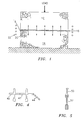
- FIG. 1 illustrates two metal members or components 12 and 14 to be joined together.
- the metal members may comprise any solid or hollow components and may be formed from any suitable metallic material known in the art such as a titanium-based or nickel-based superalloy.
- Each metal member for example, could be formed from a IN100 nickel-base alloy.
- the surfaces 18 and 20 of the metal members 12 and 14 to be joined are machined substantially parallel. It has been found to be desirable for each mating surface to have a finish of 32 AA microns or better. Any suitable means known in the art may be used to machine the surfaces. After machining, the surfaces 18 and 20 to be joined together are immersed in a cleaning solution. Any cleaning solution known in the art may be used to remove deleterious matter and other contaminants from the surfaces 18 and 20.
- a piece of interlayer foil 16 is positioned between the two metal members so as to form a joint interface.
- the interlayer foil 16 preferably comprises a low melting point, prealloyed foil having a eutectic composition, or near eutectic composition, throughout its thickness.
- the foil 16 has a composition which contains a constituent, such as boron or silicon, which depresses the melting point of the material forming the foil, thereby permitting local melting and subsequent isothermal solidification of the joint.
- One composition which has been found to be useful for the interlayer foil 16 when bonding metal members formed from a nickel based alloy is a prealloyed foil having a nominal composition of 15 wt% chromium, 3 wt% boron, and the balance essentially nickel.
- This foil composition has been found to be good for creating a joint have excellent mechanical properties such as strength and ductility.
- the interlayer foil 16 have a relatively small thickness. It has been found that foils having a thickness in the range of from about 0.0005 inches to about 0.005 inches are most useful. Preferably, the foil should have a thickness in the range of from about 0.002 inches to about 0.004 inches and most preferably, a thickness in the range of from about 0.002 inches to about 0.003 inches. If the foil has a thickness greater than 0.005 inches, it has been found that the mechanical properties of the joint fall off dramatically.
- a load is applied substantially transverse to the joint interface to urge the metallic members 12 and 14 together.
- the load may be applied either by dead weight (gravity), a hydraulic cylinder, or by virtue of differential thermal expansion. Differential thermal expansion however is not as desirable as the other two techniques mentioned above because of a lack of precise control.
- the load applied during the bonding operation should not be so large that any significant plastic deformation is caused in the surfaces 18 and 20. Any plastic deformation which is caused should be in the order of only a few ten-thousandths of an inch. Loads in the range of from about 0.01 to about 5.0 ksi, preferably in the range of from about 0.06 to about 5.0 ksi, have been found to be quite useful in the process of the present invention.
- the process of the present invention avoids problems associated with prior art techniques by using localized, rapid heating at the joint interface to form a joint having very desirable properties and characteristics.
- Localized heating may be defined as preferential heating of only the joint interface region as compared to overall heating which heats the entire part.
- the localized rapid heating is applied for a time, preferably 1 to 2 hours, so that the interlayer foil melts and forms a liquid phase at the interface.
- the heating temperature is selected to accomplish melting of the foil and certain other objectives.
- the applied temperature should be such that rim portions of the parent metals experience grain coansening and a coarse grain rim microstructure is achieved. In this way, a creep resistant, damage tolerant material is created at the rim.
- the temperature should be such that a full solution heat treat of the parent alloy occurs. It has been found that a temperature close to the melting point of the parent metal, i.e. within 50° - 60°F of the parent metal melting point, accomplishes these results. At this temperature, the parent material is also substantially homogenized. In the case of parent metals formed from a nickel-based alloy such as IN100, a temperature in the range of about 2125°F to about 2200°F is useful.
- This localized heating distinguishes the process of the present invention from other joining or bonding processes such as transient liquid phase bonding wherein heat is applied across the entire thickness of the metal members being joined.
- the localized heating may be applied by induction or resistance heating.
- an induction coil 22 may be used to provide the localized heating in the vicinity of the joint interface.
- the process of the present invention further utilizes local, controlled rate, rapid cooling at the joint interface to promote high strength.
- the localized cooling takes place at a rate of about 100°F per minute to about 800°F per minute, preferably about 200°F per minute.
- power is turned off to the induction coil or resistance heater and the joint exposed to a quench medium such as helium.
- the bonding process of the present invention is performed in a vacuum or an inert environment.
- the vacuum may be applied during the bonding process using any suitable means known in the art.
- an inert environment it may be created in any suitable fashion known in the art.
- the depressant in the foil diffuses outwardly towards the surfaces 18 and 20.
- diffusion of the melting point depressant occurs and the joint solidifies isothermally, i.e. at the bonding temperature.
- the locally heated joint is cooled rapidly as previously discussed to promote high strength properties in the joint, which are similar to the properties of the material forming the parent metal members.
- Localized heating is a key to the process of the present invention because this allows the unheated portion of the metallic members 12 and 14 to act as a heat sink to rapidly induction-cool the joint region.
- the joined metal members 12 and 14 are isothermally stress-relieved and aged. Stress relief may be performed in a furnace at a temperature of 1800°F for up to one hour, preferably about 45 minutes. The aging treatment may also be conducted in a furnace at a temperature of about 1350°F for 8 hours. By performing the stress relief and aging steps, it is possible to avoid a high temperature re-solution heat treatment of the entire assembly.
- TLP transient liquid phase bonding
- the localized heating and rapid cooling aspects of the process of the present invention are advantageous from the standpoint of preserving mechanical properties of the joint and controlling component dimensions.
- conventional bonding methods often employ differential expansion tooling which requires isothermal heating of the entire component. This technique results in ultra slow cooling rates due to the combined mass of tooling, fixturing and the actual hardware and results in mechanical property debits in tensile and fatigue capability. Rapid heating and cooling rates cannot be achieved with the TLP type process using isothermal heating of both component and tooling due to the mass of the system. While these properties can generally be recovered by subsequent reheat treatment, this will occur at the expense of dimensional control of final machined or near final machined hardware such as hollow disks, drum rotors and IBR blade repairs.
- Another significant advantage of the process of the present invention is the precision fit-up and low process induced deformation.
- a critical consideration when joining finish machined or near-net shape components is the dimensional tolerance required in the post-bond condition.
- Forge-Joining components such as hollow disk halves, drum rotor stages, and IBR replacement blades require an appreciable forge-upset at the bond line to ensure that oxide films are broken up and that intimate contact is made between the bond surfaces.
- the process of the present invention requires only that the surfaces to be bonded are sufficiently close so that the melted interlayer material can fill any surface asperities or gaps. Bond loads in this process can thus be quite low, thereby minimizing deformation of the component and promoting precise location of surfaces such as the hollow disk segments.
- interlayer foil thickness can be reduced to the minimum required to ensure a sound metallurgical bond. This is important since as discussed hereinafter thinnen interlayer foils result in a thinner melted region that must be subsequently homogenized by diffusion. This in turn reduces the time necessary to achieve a sound joint and results in a more cost efficient process.
- the low deformation is critical for precision positioning of drum rotor stages wherein various drum sections 40, 42 and 44 must be bonded together as shown in FIG. 4, for repairing IBR blades by bonding a replacement blade 50 to a rotor 52 as shown in FIG. 5.
- the use of a prealloyed interlayer foil in the process of the present invention is also quite significant.
- the prealloyed interlayer foil when employed to bond nickel-base alloys, contains boron as a melting point depressant.
- boron as a melting point depressant.
- concentration of boron in the melted region is uniform through the thickness of the foil being melted.
- boron begins to move into the substrate according to well known laws of diffusion, creating a concentration gradient.
- the highest concentration of boron remains at the center of the melted joint and decreases toward the interface between the substrate and the melt. When the critical value of boron concentration is reached, solidification will commence.
- the foil interlayer can be formed from a titanium based alloy having a depressant constituent.
- the process of the present invention may be performed with multiple foil layers at the joint interface.
Landscapes
- Engineering & Computer Science (AREA)
- Mechanical Engineering (AREA)
- Pressure Welding/Diffusion-Bonding (AREA)
Priority Applications (1)
| Application Number | Priority Date | Filing Date | Title |
|---|---|---|---|
| EP03029826A EP1439022B1 (fr) | 1997-07-22 | 1998-06-10 | Connexion d'élements métalliques |
Applications Claiming Priority (2)
| Application Number | Priority Date | Filing Date | Title |
|---|---|---|---|
| US903230 | 1997-07-22 | ||
| US08/903,230 US6098871A (en) | 1997-07-22 | 1997-07-22 | Process for bonding metallic members using localized rapid heating |
Publications (3)
| Publication Number | Publication Date |
|---|---|
| EP0893188A2 true EP0893188A2 (fr) | 1999-01-27 |
| EP0893188A3 EP0893188A3 (fr) | 1999-08-18 |
| EP0893188B1 EP0893188B1 (fr) | 2004-01-02 |
Family
ID=25417146
Family Applications (2)
| Application Number | Title | Priority Date | Filing Date |
|---|---|---|---|
| EP98401402A Expired - Lifetime EP0893188B1 (fr) | 1997-07-22 | 1998-06-10 | Méthode de connexion d'éléments métalliques |
| EP03029826A Expired - Lifetime EP1439022B1 (fr) | 1997-07-22 | 1998-06-10 | Connexion d'élements métalliques |
Family Applications After (1)
| Application Number | Title | Priority Date | Filing Date |
|---|---|---|---|
| EP03029826A Expired - Lifetime EP1439022B1 (fr) | 1997-07-22 | 1998-06-10 | Connexion d'élements métalliques |
Country Status (4)
| Country | Link |
|---|---|
| US (1) | US6098871A (fr) |
| EP (2) | EP0893188B1 (fr) |
| JP (1) | JP3086950B2 (fr) |
| DE (1) | DE69820814T2 (fr) |
Cited By (4)
| Publication number | Priority date | Publication date | Assignee | Title |
|---|---|---|---|---|
| EP1231010A1 (fr) * | 2001-02-08 | 2002-08-14 | Siemens Westinghouse Power Corporation | Réparation d'aubes de turbines par assemblage en phase liquide transitoire |
| EP2093375A3 (fr) * | 2008-02-21 | 2012-10-03 | United Technologies Corporation | Procédé de réparation de redresseurs en porte-à-faux |
| EP2808113B1 (fr) | 2013-05-30 | 2017-01-04 | General Electric Company | Processus de brasage-diffusion hybride |
| EP3308900A1 (fr) * | 2016-10-13 | 2018-04-18 | United Technologies Corporation | Composant optique intégré et procédé de fabrication |
Families Citing this family (24)
| Publication number | Priority date | Publication date | Assignee | Title |
|---|---|---|---|---|
| US6331361B1 (en) * | 1998-11-19 | 2001-12-18 | Hickham Industries, Inc. | Methods for manufacture and repair and resulting components with directionally solidified or single crystal materials |
| US6193141B1 (en) * | 2000-04-25 | 2001-02-27 | Siemens Westinghouse Power Corporation | Single crystal turbine components made using a moving zone transient liquid phase bonded sandwich construction |
| US6974070B2 (en) * | 2001-08-07 | 2005-12-13 | University Of Chicago | Joining of advanced materials by superplastic deformation |
| US6902096B2 (en) * | 2001-10-29 | 2005-06-07 | United Technologies Corporation | Method of joining material |
| EP1437426A1 (fr) * | 2003-01-10 | 2004-07-14 | Siemens Aktiengesellschaft | Procédé de production des structures monocristallines |
| JP4540392B2 (ja) * | 2003-06-02 | 2010-09-08 | 新日本製鐵株式会社 | 金属機械部品の液相拡散接合方法 |
| US7775414B2 (en) * | 2003-10-04 | 2010-08-17 | Siemens Energy, Inc. | Consumable insert and method of using the same |
| US7565996B2 (en) * | 2004-10-04 | 2009-07-28 | United Technologies Corp. | Transient liquid phase bonding using sandwich interlayers |
| JP4909992B2 (ja) * | 2005-09-08 | 2012-04-04 | インキュメッド・リミテッド・ライアビリティ・カンパニー | チタンベースのメッシュをチタンベースの基板に接合するための方法 |
| US20100031627A1 (en) * | 2008-08-07 | 2010-02-11 | United Technologies Corp. | Heater Assemblies, Gas Turbine Engine Systems Involving Such Heater Assemblies and Methods for Manufacturing Such Heater Assemblies |
| US20110129687A1 (en) * | 2009-11-30 | 2011-06-02 | Honeywell International Inc. | Methods of joining a first component and a second component to form a bond joint and assemblies having bond joints |
| JP5796299B2 (ja) * | 2011-02-02 | 2015-10-21 | 三菱マテリアル株式会社 | ヒートシンク付パワーモジュール用基板、ヒートシンク付パワーモジュール用基板の製造方法及びパワーモジュール |
| US8803001B2 (en) | 2011-06-21 | 2014-08-12 | Toyota Motor Engineering & Manufacturing North America, Inc. | Bonding area design for transient liquid phase bonding process |
| JP5910166B2 (ja) * | 2012-02-29 | 2016-04-27 | 三菱マテリアル株式会社 | パワーモジュール用基板の製造方法 |
| ES2706986T3 (es) * | 2012-03-28 | 2019-04-02 | Alfa Laval Corp Ab | Nuevo concepto de soldadura fuerte |
| US9044822B2 (en) | 2012-04-17 | 2015-06-02 | Toyota Motor Engineering & Manufacturing North America, Inc. | Transient liquid phase bonding process for double sided power modules |
| US10058951B2 (en) | 2012-04-17 | 2018-08-28 | Toyota Motor Engineering & Manufacturing North America, Inc. | Alloy formation control of transient liquid phase bonding |
| US9938834B2 (en) | 2015-04-30 | 2018-04-10 | Honeywell International Inc. | Bladed gas turbine engine rotors having deposited transition rings and methods for the manufacture thereof |
| US10294804B2 (en) | 2015-08-11 | 2019-05-21 | Honeywell International Inc. | Dual alloy gas turbine engine rotors and methods for the manufacture thereof |
| US10036254B2 (en) | 2015-11-12 | 2018-07-31 | Honeywell International Inc. | Dual alloy bladed rotors suitable for usage in gas turbine engines and methods for the manufacture thereof |
| US20170144260A1 (en) * | 2015-11-24 | 2017-05-25 | General Electric Company | Article treatment method and treated article |
| DE102016206558A1 (de) | 2016-04-19 | 2017-10-19 | MTU Aero Engines AG | Verfahren und Vorrichtung zum Herstellen zumindest eines Bauteilbereichs eines Bauteils |
| US10946476B2 (en) | 2017-05-11 | 2021-03-16 | Raytheon Technologies Corporation | Heat treatment and stress relief for solid-state welded nickel alloys |
| DE102020203502A1 (de) * | 2020-03-18 | 2021-09-23 | Mahle International Gmbh | Verfahren zum Herstellen eines Wärmeübertragers |
Family Cites Families (25)
| Publication number | Priority date | Publication date | Assignee | Title |
|---|---|---|---|---|
| US3678570A (en) * | 1971-04-01 | 1972-07-25 | United Aircraft Corp | Diffusion bonding utilizing transient liquid phase |
| BE795663A (fr) * | 1972-03-20 | 1973-06-18 | United Aircraft Corp | Feuille intermediaire pour soudures par diffusion |
| FR2511908A1 (fr) * | 1981-08-26 | 1983-03-04 | Snecma | Procede de brasage-diffusion destine aux pieces en superalliages |
| SE447804B (sv) * | 1983-04-20 | 1986-12-15 | Kuroki Kogyosho Kk | Forfarande for framstellning av sammansatta stalror |
| JPS6064656A (ja) * | 1983-09-16 | 1985-04-13 | Mitsubishi Kakoki Kaisha Ltd | 遠心分離機のスクリユウ羽根 |
| US4608094A (en) * | 1984-12-18 | 1986-08-26 | United Technologies Corporation | Method of producing turbine disks |
| US4700881A (en) * | 1984-12-20 | 1987-10-20 | United Technologies Corporation | Multiple foil transient liquid phase bonding |
| DE3664930D1 (en) * | 1985-03-15 | 1989-09-14 | Bbc Brown Boveri & Cie | Process for enhancing the oxidation and corrosion resistance of a component made from a dispersion-hardened superalloy by means of a surface treatment |
| US5145105A (en) * | 1986-03-13 | 1992-09-08 | United Technologies Corporation | Diffusion bonding process |
| DE3863683D1 (de) * | 1987-04-13 | 1991-08-22 | Bbc Brown Boveri & Cie | Befestigung einer deckplatte an dem blatt einer turbomaschinenschaufel. |
| JP2778705B2 (ja) * | 1988-09-30 | 1998-07-23 | 日立金属株式会社 | Ni基超耐熱合金およびその製造方法 |
| FR2641210B1 (fr) * | 1989-01-03 | 1991-03-15 | Valinox | Procede de fabrication de tubes bimetalliques et tubes obtenus par ce procede |
| US4919323A (en) * | 1989-06-05 | 1990-04-24 | Rockwell International Corporation | Diffusion bonding nickel base alloys |
| US5118028A (en) * | 1989-08-29 | 1992-06-02 | Sumitomo Metal Industries, Ltd. | Diffusion bonding method for corrosion-resistant materials |
| US5100050A (en) * | 1989-10-04 | 1992-03-31 | General Electric Company | Method of manufacturing dual alloy turbine disks |
| US5061324A (en) * | 1990-04-02 | 1991-10-29 | General Electric Company | Thermomechanical processing for fatigue-resistant nickel based superalloys |
| US5272809A (en) * | 1990-09-04 | 1993-12-28 | United Technologies Corporation | Technique for direct bonding cast and wrought materials |
| US5106010A (en) * | 1990-09-28 | 1992-04-21 | Chromalloy Gas Turbine Corporation | Welding high-strength nickel base superalloys |
| US5176499A (en) * | 1991-06-24 | 1993-01-05 | General Electric Company | Photoetched cooling slots for diffusion bonded airfoils |
| US5312497A (en) * | 1991-12-31 | 1994-05-17 | United Technologies Corporation | Method of making superalloy turbine disks having graded coarse and fine grains |
| US5273708A (en) * | 1992-06-23 | 1993-12-28 | Howmet Corporation | Method of making a dual alloy article |
| US5413752A (en) * | 1992-10-07 | 1995-05-09 | General Electric Company | Method for making fatigue crack growth-resistant nickel-base article |
| DE69500502T2 (de) * | 1994-02-08 | 1998-02-12 | Sumitomo Metal Ind | Verfahren zur Herstellung eines plattierten Rohres |
| US5571345A (en) * | 1994-06-30 | 1996-11-05 | General Electric Company | Thermomechanical processing method for achieving coarse grains in a superalloy article |
| JP3511749B2 (ja) * | 1995-08-30 | 2004-03-29 | 大同特殊鋼株式会社 | Ti合金部材の接合方法 |
-
1997
- 1997-07-22 US US08/903,230 patent/US6098871A/en not_active Expired - Lifetime
-
1998
- 1998-06-10 EP EP98401402A patent/EP0893188B1/fr not_active Expired - Lifetime
- 1998-06-10 DE DE69820814T patent/DE69820814T2/de not_active Expired - Lifetime
- 1998-06-10 EP EP03029826A patent/EP1439022B1/fr not_active Expired - Lifetime
- 1998-07-10 JP JP10210307A patent/JP3086950B2/ja not_active Expired - Fee Related
Cited By (4)
| Publication number | Priority date | Publication date | Assignee | Title |
|---|---|---|---|---|
| EP1231010A1 (fr) * | 2001-02-08 | 2002-08-14 | Siemens Westinghouse Power Corporation | Réparation d'aubes de turbines par assemblage en phase liquide transitoire |
| EP2093375A3 (fr) * | 2008-02-21 | 2012-10-03 | United Technologies Corporation | Procédé de réparation de redresseurs en porte-à-faux |
| EP2808113B1 (fr) | 2013-05-30 | 2017-01-04 | General Electric Company | Processus de brasage-diffusion hybride |
| EP3308900A1 (fr) * | 2016-10-13 | 2018-04-18 | United Technologies Corporation | Composant optique intégré et procédé de fabrication |
Also Published As
| Publication number | Publication date |
|---|---|
| EP0893188B1 (fr) | 2004-01-02 |
| JP3086950B2 (ja) | 2000-09-11 |
| EP1439022A2 (fr) | 2004-07-21 |
| EP1439022B1 (fr) | 2011-07-27 |
| JPH1190649A (ja) | 1999-04-06 |
| US6098871A (en) | 2000-08-08 |
| EP0893188A3 (fr) | 1999-08-18 |
| EP1439022A3 (fr) | 2004-08-04 |
| DE69820814D1 (de) | 2004-02-05 |
| DE69820814T2 (de) | 2004-10-21 |
Similar Documents
| Publication | Publication Date | Title |
|---|---|---|
| EP0893188B1 (fr) | Méthode de connexion d'éléments métalliques | |
| US5161950A (en) | Dual alloy turbine disk | |
| KR101570139B1 (ko) | 터보기계의 로터 샤프트, 및 터보기계의 로터의 제조 방법 | |
| US6291086B1 (en) | Friction welding interlayer and method for joining gamma titanium aluminide to steel, and turbocharger components thereof | |
| US7156282B1 (en) | Titanium-aluminide turbine wheel and shaft assembly, and method for making same | |
| US5111570A (en) | Forge joining repair technique | |
| US5100050A (en) | Method of manufacturing dual alloy turbine disks | |
| US6638639B1 (en) | Turbine components comprising thin skins bonded to superalloy substrates | |
| JP4721659B2 (ja) | 高強度材料を摩擦撹拌接合するための装置及び方法、並びにこれから製造される物品 | |
| EP3995594B1 (fr) | Soudage à l'état solide de métallurgie des poudres à grains grossiers de superalliages à base de nickel | |
| EP1526252B1 (fr) | Procédé de production d'un rotor de turbine avec des propriétés triples | |
| US6325871B1 (en) | Method of bonding cast superalloys | |
| US8242406B2 (en) | Method for the manufacture of a blisk | |
| EP1837117A1 (fr) | Soudage de superalliages avec utilisation d'une couche intermédiaire | |
| JP2009056512A (ja) | 異種金属の接合方法並びに関連装置 | |
| US3711936A (en) | Method for forming composite articles from alloy in temporary condition of superplasticity | |
| Arhami et al. | Microstructural evolution and mechanical properties evaluation of IN-939 bonds made by isothermal solidification of a liquated Ni-Cr-B interlayer | |
| US5284290A (en) | Fusion welding with self-generated filler metal | |
| US6378755B1 (en) | Joined structure utilizing a ceramic foam bonding element, and its fabrication | |
| US11833606B1 (en) | Solid state diffusion bonding of refractory metals and their alloys | |
| JP2000263247A (ja) | 方向制御結晶合金部品の補修方法 | |
| US3779721A (en) | Composite metal having bonded members of beryllium | |
| US3748107A (en) | Superalloy eutectic braze | |
| JPH108924A (ja) | 大型ディーゼルエンジン用バルブの製造方法 | |
| JPH11123567A (ja) | チタン合金部品間の金属間接合の接合強度を高めるためのプロセス |
Legal Events
| Date | Code | Title | Description |
|---|---|---|---|
| PUAI | Public reference made under article 153(3) epc to a published international application that has entered the european phase |
Free format text: ORIGINAL CODE: 0009012 |
|
| AK | Designated contracting states |
Kind code of ref document: A2 Designated state(s): DE FR GB |
|
| AX | Request for extension of the european patent |
Free format text: AL;LT;LV;MK;RO;SI |
|
| PUAL | Search report despatched |
Free format text: ORIGINAL CODE: 0009013 |
|
| AK | Designated contracting states |
Kind code of ref document: A3 Designated state(s): AT BE CH CY DE DK ES FI FR GB GR IE IT LI LU MC NL PT SE |
|
| AX | Request for extension of the european patent |
Free format text: AL;LT;LV;MK;RO;SI |
|
| 17P | Request for examination filed |
Effective date: 19990915 |
|
| AKX | Designation fees paid |
Free format text: DE FR GB |
|
| 17Q | First examination report despatched |
Effective date: 20020809 |
|
| GRAP | Despatch of communication of intention to grant a patent |
Free format text: ORIGINAL CODE: EPIDOSNIGR1 |
|
| GRAS | Grant fee paid |
Free format text: ORIGINAL CODE: EPIDOSNIGR3 |
|
| GRAA | (expected) grant |
Free format text: ORIGINAL CODE: 0009210 |
|
| AK | Designated contracting states |
Kind code of ref document: B1 Designated state(s): DE FR GB |
|
| REG | Reference to a national code |
Ref country code: GB Ref legal event code: FG4D |
|
| REF | Corresponds to: |
Ref document number: 69820814 Country of ref document: DE Date of ref document: 20040205 Kind code of ref document: P |
|
| ET | Fr: translation filed | ||
| PLBE | No opposition filed within time limit |
Free format text: ORIGINAL CODE: 0009261 |
|
| STAA | Information on the status of an ep patent application or granted ep patent |
Free format text: STATUS: NO OPPOSITION FILED WITHIN TIME LIMIT |
|
| 26N | No opposition filed |
Effective date: 20041005 |
|
| PGFP | Annual fee paid to national office [announced via postgrant information from national office to epo] |
Ref country code: FR Payment date: 20100709 Year of fee payment: 13 |
|
| REG | Reference to a national code |
Ref country code: FR Ref legal event code: ST Effective date: 20120229 |
|
| PG25 | Lapsed in a contracting state [announced via postgrant information from national office to epo] |
Ref country code: FR Free format text: LAPSE BECAUSE OF NON-PAYMENT OF DUE FEES Effective date: 20110630 |
|
| PGFP | Annual fee paid to national office [announced via postgrant information from national office to epo] |
Ref country code: DE Payment date: 20120607 Year of fee payment: 15 |
|
| PGFP | Annual fee paid to national office [announced via postgrant information from national office to epo] |
Ref country code: GB Payment date: 20120606 Year of fee payment: 15 |
|
| GBPC | Gb: european patent ceased through non-payment of renewal fee |
Effective date: 20130610 |
|
| REG | Reference to a national code |
Ref country code: DE Ref legal event code: R119 Ref document number: 69820814 Country of ref document: DE Effective date: 20140101 |
|
| PG25 | Lapsed in a contracting state [announced via postgrant information from national office to epo] |
Ref country code: DE Free format text: LAPSE BECAUSE OF NON-PAYMENT OF DUE FEES Effective date: 20140101 Ref country code: GB Free format text: LAPSE BECAUSE OF NON-PAYMENT OF DUE FEES Effective date: 20130610 |