EP0893205A1 - Ringstreifen zum Halten von Befestigungsdübeln und Setzgerät dafür - Google Patents
Ringstreifen zum Halten von Befestigungsdübeln und Setzgerät dafür Download PDFInfo
- Publication number
- EP0893205A1 EP0893205A1 EP98401396A EP98401396A EP0893205A1 EP 0893205 A1 EP0893205 A1 EP 0893205A1 EP 98401396 A EP98401396 A EP 98401396A EP 98401396 A EP98401396 A EP 98401396A EP 0893205 A1 EP0893205 A1 EP 0893205A1
- Authority
- EP
- European Patent Office
- Prior art keywords
- strip
- buffer
- rings
- sealing
- holding
- Prior art date
- Legal status (The legal status is an assumption and is not a legal conclusion. Google has not performed a legal analysis and makes no representation as to the accuracy of the status listed.)
- Granted
Links
- 238000007789 sealing Methods 0.000 claims abstract description 28
- 238000010304 firing Methods 0.000 claims abstract description 7
- 239000000872 buffer Substances 0.000 claims description 89
- 238000005192 partition Methods 0.000 description 5
- 230000004323 axial length Effects 0.000 description 4
- 239000000843 powder Substances 0.000 description 4
- 239000000567 combustion gas Substances 0.000 description 2
- 238000012423 maintenance Methods 0.000 description 2
- 235000008612 Gnetum gnemon Nutrition 0.000 description 1
- 240000000018 Gnetum gnemon Species 0.000 description 1
- 238000004140 cleaning Methods 0.000 description 1
- 230000002950 deficient Effects 0.000 description 1
- 230000014759 maintenance of location Effects 0.000 description 1
- 210000000056 organ Anatomy 0.000 description 1
Images

Classifications
-
- F—MECHANICAL ENGINEERING; LIGHTING; HEATING; WEAPONS; BLASTING
- F16—ENGINEERING ELEMENTS AND UNITS; GENERAL MEASURES FOR PRODUCING AND MAINTAINING EFFECTIVE FUNCTIONING OF MACHINES OR INSTALLATIONS; THERMAL INSULATION IN GENERAL
- F16B—DEVICES FOR FASTENING OR SECURING CONSTRUCTIONAL ELEMENTS OR MACHINE PARTS TOGETHER, e.g. NAILS, BOLTS, CIRCLIPS, CLAMPS, CLIPS OR WEDGES; JOINTS OR JOINTING
- F16B15/00—Nails; Staples
- F16B15/08—Nails; Staples formed in integral series but easily separable
-
- B—PERFORMING OPERATIONS; TRANSPORTING
- B25—HAND TOOLS; PORTABLE POWER-DRIVEN TOOLS; MANIPULATORS
- B25C—HAND-HELD NAILING OR STAPLING TOOLS; MANUALLY OPERATED PORTABLE STAPLING TOOLS
- B25C1/00—Hand-held nailing tools; Nail feeding devices
- B25C1/08—Hand-held nailing tools; Nail feeding devices operated by combustion pressure
- B25C1/10—Hand-held nailing tools; Nail feeding devices operated by combustion pressure generated by detonation of a cartridge
- B25C1/18—Details and accessories, e.g. splinter guards, spall minimisers
- B25C1/182—Feeding devices
- B25C1/184—Feeding devices for nails
Definitions
- the field of the invention is that of tampon sealing by means of a sealing device with driving weight buffers, powered by the combustion gas of charges of powder, and buffer magazine, linked to the barrel and the buffer guide the device.
- Such devices for the use of buffer strips to be introduced in the loader and comprising a plurality of receiving rings of buffer linked together by fragile connecting partitions intended to be cut, the reception rings, for their part, being destroyed during the seals.
- the assembly After inserting a stamp, and its reception ring, in the buffer guide, the assembly remains correctly maintained there, that is to say with the pad axis coincident with that of the pad guide, thanks to the adjacent reception rings or even to the last ring for the penultimate. So the pads are correctly guided, without deviation, during their propulsion by the flyweight. It is not the same for the last buffer whose reception ring is no longer connected to another. Its guidance in the pad guide may therefore be defective.
- the present invention aims first of all to eliminate this risk.
- the invention relates to a band of reception rings of sealing pads connected to each other, for charger sealing device, characterized in that one of the rings end of the strip is secured to a holding member and guide intended to hold and guide the tampon perfectly until it is propelled, without risk of it going wrong.
- the holding and guiding member is arranged to cooperate with a loader thrust member.
- the holding and guiding member is arranged to be detachably mounted in translation in the thrust member, until it is ejected at the end of opening of the charger.
- the holding and guiding member can be constituted a screed for receiving a push finger from the loader, window for receiving a lug of the pushing finger.
- the holding and guiding member is integral with a anti-ignition device, preventing any ignition after use of the last buffer ring, advantageously a crutch arranged for, after introduction into a supply light of buffer, limit the stroke of the barrel of the device.
- the buffer receiving rings are extended by a portion of the lateral positioning skirt of the rings after setting the device down, to ensure the quality of the seals.
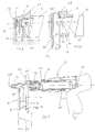
- the strip of buffers 1 is intended to supply an appliance 20 of sealing of buffers with counterweight 21 for driving buffers, powered by the powder charge combustion gas.
- the tampon sealing apparatus includes a barrel 22 mounted sliding in a barrel holder 23 and secured in axial translation a front buffer guide 24 in which the counterweight can slide 21 buffer drive, a rear device 25 for setting fire loads of powder and a handle 26 with a trigger 27 for controlling the firing device 25.
- the buffer guide 24 provided with a supply light 28 buffer consisting of a slot parallel to the axis 29 of the buffer guide 24, of axial length F and of width equal to the diameter exterior of buffer receiving rings described below.
- the tampon sealing apparatus 20 further comprises a magazine 30, mounted on the buffer guide 24, comprising a magazine 31 for receiving the strip of buffers 1 and a door for inserting and ejecting the strip 1.
- the buffer guide 24 and the barrel 22 may slide slightly backwards relative to the charger against the action of return springs 34.
- the magazine 31 for receiving the buffer strip 1 extends along a longitudinal axis 35 perpendicular to the axis 29 of the buffer guide 24 and is open to light 28 supply right of buffer for the passage of buffers.
- the interior of the store supply 31 contains a member 32 for pushing the strip 1, provided with a pushing finger 33, and an ejection pin 38 making projection of an interior wall of the magazine 31.
- the pushing member 32 is mounted on a thrust spring, not shown, extending the along the axis 35 of the magazine 31, under the action of which the push 32 is pushed along the axis 35 of the magazine towards the buffer passage opening.
- the push finger 33 of the buffer strip 1 is provided with a lug 36 intended to secure in translation along the axis 35, of detachably, the pushing member 32 and the strip of buffers 1 as will be explained later.
- the buffer strip 1 comprises a plurality of rings 2 of receipt of buffer 5, in this case ten rings, interconnected, the along the longitudinal axis 3 of the strip 1, by fragile partitions of link 4 intended to be sectioned. Rings 2 are each intended to tighten a pad 5 and to maintain the axis of this pad 5 perpendicular to the longitudinal axis 3 of the strip 1.
- Each buffer reception ring 2 5 has a shape general tubular and includes two clamps 6, 7, posterior and anterior, connected to each other by two ribs 8, 9 parallel to the axis of the ring.
- One of the two cable ties, the anterior collar 7, is extended at the front along the axis of the ring, by a portion 10 of lateral positioning skirt.
- Diameters inside and outside of ring 2 are respectively equal to diameter of the buffer rod 5 and at the bore of the buffer guide 24.
- One of the end rings 11 of the strip 1, the tail ring, is secured, by means of a fragile connecting partition intended to be sectioned, of a holding and guiding member 13 intended to perfectly maintain and guide the buffer 5 until it propulsion, without risk of it going wrong.
- the holding and guiding member 13 consists of a yoke reception of the pushing finger 33 from the pushing member 32 of the charger 31.
- the receiving finger for the pushing finger 33 has the shape of a jaw for gripping the pushing finger 33 of the charger 30 comprising two branches 14, 15 in a U, one of which 14 cleaning a window 37 for receiving the pin 36 of the finger push 33.
- the holding and guiding member 13 is further provided with a anti-ignition kickstand 16 extending the receiving screed thrust pin perpendicular to the longitudinal axis 3 of the band of rings 1, on the anterior side of band 1 extended by the portions 10 of positioning skirt.
- the reception screed provided with its anti-ignition kickstand 16 has a width total, perpendicular to the longitudinal axis 3 of the strip of rings 1, substantially equal to the axial length F of the light supply 28 of the buffer guide 24.
- the anti-stake stand fire 16 is thus intended, after introduction into the light 28 buffer supply, to limit the stroke of the barrel 22 of the apparatus 20 as will be explained later.
- Buffers 5 inserted in the band reception rings by the posterior side of the band protrude, from the anterior side of the strip, by their pointed end portion 17, of a length given 1.
- buffer strip 1 for sealing buffers 5 using the sealer 20
- the strip of stamps 1 is introduced into the magazine 31 for receiving loader buffers 30, so that the axes of the buffers 5 extend parallel to the axis 29 of the buffer guide 24.
- the pushing finger 33 is inserted into its receiving yoke 13 of the strip of buffers 1, the lug 36 of the pushing finger 33 being snapped into the window 37 of the receiving yoke 13 so as to securely detachable, in translation along the axis longitudinal 35 of magazine 31, the pushing finger 33 and the strip of stamps 1.
- the buffer strip 1 Under the thrust of the thrust spring, the buffer strip 1 is then pushed along the longitudinal axis 35 of the magazine towards the pad guide 24, until the head pad, and its ring head 12, from the end of the strip 1 opposite the end provided of the tail ring 11 are introduced into the buffer guide 24 through its supply window 28. Correct maintenance of the buffer and its ring 12, with the axis of the buffer coincident with that 29 of the buffer guide 24, is provided by the receiving ring adjacent.
- the free front end of the buffer guide 24 is then brought into bearing against a bearing surface 40, here a wall, and the apparatus sealing 20 is slightly pushed against the wall 40 so as to slide the buffer guide 24 and the barrel 23 backwards compared to the buffer loader 30.
- the light supply 28 of buffer guide 24 shifts backwards compared to the opening for the passage of buffers in the magazine supply 31.
- the axial length of the back guide sliding 24 is such that the front edge 28 'of the supply light 28 is, at the end of the travel, substantially in the plane extending between the front collars 7 of the band of rings 2 and the portions 10 of lateral positioning skirt.
- the portion of skirt of the ring 12 of the head pad is then in contact with the inner wall of the buffer guide 24, near the front edge 28 '.
- the skirt portion thus ensures lateral positioning and the correct retention of the head pad and its ring 12 in the pad guide 24, with the buffer 5 axis coincident with that of the buffer guide 29 24, without risk that the pad will skew up to its propulsion, for good quality seals.
- the user then presses the trigger 27 of the sealing 20 so as to trigger the firing of the charges of powder and propel the flyweight 21 which comes strike the head pad by propelling it forward.
- the partition 4 connecting the head pad and the adjacent buffer is severed, ring 2 of the buffer being destroyed when sealing in the wall.
- the anti-stake stand to fire 16 is introduced into the supply light 28 buffer under the thrust of the thrust spring and thus limits the stroke of the buffer guide 24 and of the barrel 22 of the device 20 in preventing ignition.
- the user After using the last buffer of the strip, and its ring 11, the user opens the magazine by his ejection door and pulls the organ thrust 32, always integral in translation with the body of holding and guiding 13, opposite to the direction of thrust, until the holding and guiding member 13, at the end opening the magazine 30, come up against the ejection pin 38 of the charger 30 by causing the unclipping finger 36 to unclip and therefore the ejection of the holding and guiding member 13.
- the anti-firing member is a stand 16 secured to the holding and guiding member 13 of strip 1 of buffer reception rings 5.
- the charger 30 could include a ejection stopper intended to cooperate with the ejection lug for ejection of the holding and guiding member at the end of opening of the charger.
Landscapes
- Engineering & Computer Science (AREA)
- Mechanical Engineering (AREA)
- General Engineering & Computer Science (AREA)
- Combustion & Propulsion (AREA)
- Chemical & Material Sciences (AREA)
- Portable Nailing Machines And Staplers (AREA)
- Absorbent Articles And Supports Therefor (AREA)
- Processing Of Terminals (AREA)
- Cable Accessories (AREA)
- Automatic Assembly (AREA)
- Sealing Of Jars (AREA)
- Clamps And Clips (AREA)
- Heating, Cooling, Or Curing Plastics Or The Like In General (AREA)
Applications Claiming Priority (2)
| Application Number | Priority Date | Filing Date | Title |
|---|---|---|---|
| FR9709493 | 1997-07-25 | ||
| FR9709493A FR2766403B1 (fr) | 1997-07-25 | 1997-07-25 | Bande de bagues de reception de tampon de scellement pour appareil de scellement de tampon |
Publications (2)
| Publication Number | Publication Date |
|---|---|
| EP0893205A1 true EP0893205A1 (de) | 1999-01-27 |
| EP0893205B1 EP0893205B1 (de) | 2004-02-04 |
Family
ID=9509633
Family Applications (1)
| Application Number | Title | Priority Date | Filing Date |
|---|---|---|---|
| EP98401396A Expired - Lifetime EP0893205B1 (de) | 1997-07-25 | 1998-06-10 | Ringstreifen zum Halten von Befestigungsdübeln und Setzgerät dafür |
Country Status (6)
| Country | Link |
|---|---|
| EP (1) | EP0893205B1 (de) |
| AT (1) | ATE258841T1 (de) |
| DE (1) | DE69821411T2 (de) |
| ES (1) | ES2214686T3 (de) |
| FR (1) | FR2766403B1 (de) |
| NO (1) | NO983443L (de) |
Cited By (3)
| Publication number | Priority date | Publication date | Assignee | Title |
|---|---|---|---|---|
| EP1400314A1 (de) * | 2002-09-18 | 2004-03-24 | Illinois Tool Works Inc. | Sperreinrichtung für pulverkraftbetriebenes Werkzeug |
| WO2004061314A3 (en) * | 2002-12-18 | 2004-10-07 | Powers Fasteners Inc | Fastener carrier assembly and method of use |
| EP1391268A3 (de) * | 2002-08-19 | 2008-11-12 | Illinois Tool Works Inc. | Werkzeug für Befestigungsmittel mit Magazin-Schlepphebel |
Families Citing this family (1)
| Publication number | Priority date | Publication date | Assignee | Title |
|---|---|---|---|---|
| US7328826B2 (en) | 2005-03-28 | 2008-02-12 | Illinois Tool Works Inc. | Power nailer with driver blade blocking mechanism magazine |
Citations (4)
| Publication number | Priority date | Publication date | Assignee | Title |
|---|---|---|---|---|
| FR2111359A5 (de) * | 1970-10-15 | 1972-06-02 | Omark Industries Inc | |
| FR2158865A5 (de) * | 1971-10-04 | 1973-06-15 | Inzoli Giovanni | |
| DE2314920A1 (de) * | 1973-03-26 | 1974-10-03 | Rapid Befestigungstech Gmbh | Bolzensetzgeraet mit bolzenmagazin |
| FR2628021A1 (fr) * | 1988-03-02 | 1989-09-08 | Hilti Ag | Appareil de scellement actionne par l'energie de la poudre |
-
1997
- 1997-07-25 FR FR9709493A patent/FR2766403B1/fr not_active Expired - Fee Related
-
1998
- 1998-06-10 EP EP98401396A patent/EP0893205B1/de not_active Expired - Lifetime
- 1998-06-10 AT AT98401396T patent/ATE258841T1/de not_active IP Right Cessation
- 1998-06-10 ES ES98401396T patent/ES2214686T3/es not_active Expired - Lifetime
- 1998-06-10 DE DE69821411T patent/DE69821411T2/de not_active Expired - Fee Related
- 1998-07-24 NO NO983443A patent/NO983443L/no not_active Application Discontinuation
Patent Citations (4)
| Publication number | Priority date | Publication date | Assignee | Title |
|---|---|---|---|---|
| FR2111359A5 (de) * | 1970-10-15 | 1972-06-02 | Omark Industries Inc | |
| FR2158865A5 (de) * | 1971-10-04 | 1973-06-15 | Inzoli Giovanni | |
| DE2314920A1 (de) * | 1973-03-26 | 1974-10-03 | Rapid Befestigungstech Gmbh | Bolzensetzgeraet mit bolzenmagazin |
| FR2628021A1 (fr) * | 1988-03-02 | 1989-09-08 | Hilti Ag | Appareil de scellement actionne par l'energie de la poudre |
Cited By (7)
| Publication number | Priority date | Publication date | Assignee | Title |
|---|---|---|---|---|
| EP1391268A3 (de) * | 2002-08-19 | 2008-11-12 | Illinois Tool Works Inc. | Werkzeug für Befestigungsmittel mit Magazin-Schlepphebel |
| EP1400314A1 (de) * | 2002-09-18 | 2004-03-24 | Illinois Tool Works Inc. | Sperreinrichtung für pulverkraftbetriebenes Werkzeug |
| US7021511B2 (en) | 2002-09-18 | 2006-04-04 | Illinois Tool Works Inc. | Lock-out mechanism for powder actuated tool |
| AU2003244628B2 (en) * | 2002-09-18 | 2006-05-11 | Illinois Tool Works Inc. | Lock-out mechanism for powder actuated tool |
| WO2004061314A3 (en) * | 2002-12-18 | 2004-10-07 | Powers Fasteners Inc | Fastener carrier assembly and method of use |
| US7021462B2 (en) * | 2002-12-18 | 2006-04-04 | Powers Fasteners, Inc. | Fastener carrier assembly and method of use |
| CN100408449C (zh) * | 2002-12-18 | 2008-08-06 | 动力拉链公司 | 紧固件托架组件和使用方法 |
Also Published As
| Publication number | Publication date |
|---|---|
| FR2766403A1 (fr) | 1999-01-29 |
| DE69821411D1 (de) | 2004-03-11 |
| NO983443L (no) | 1999-01-26 |
| NO983443D0 (no) | 1998-07-24 |
| ES2214686T3 (es) | 2004-09-16 |
| ATE258841T1 (de) | 2004-02-15 |
| EP0893205B1 (de) | 2004-02-04 |
| FR2766403B1 (fr) | 1999-09-17 |
| DE69821411T2 (de) | 2004-07-01 |
Similar Documents
| Publication | Publication Date | Title |
|---|---|---|
| FR2554035A1 (fr) | Sabot d'alimentation d'agrafes reversible et systeme de fermeture pour le magasin d'un outil d'enfoncement d'agrafes | |
| EP0798084B1 (de) | Eintreibgerät für Befestigungsmittel mit einem automatisch zur Initialposition zurückkehrenden Kolben | |
| FR2628021A1 (fr) | Appareil de scellement actionne par l'energie de la poudre | |
| FR2616347A1 (fr) | Chargeur pour bandes de munitions a amorces pour arme-jouet; arme-jouet propre a utiliser un tel chargeur | |
| EP1304490B1 (de) | Streifen von Befestigungsmitteln und Magazin mit solchen Streifen für ein Antriebswerkzeug solcher Befestigungsmittel | |
| EP0727285A1 (de) | Setzgerät mit Kolben, angetrieben mit komprimierten Gas | |
| EP1500472A1 (de) | Eintreibwerkzeug für Befestigungsmittel mit Sicherheitsklinke | |
| EP1349451B1 (de) | Unterwasserharpune vom armbrusttyp mit spannvorrichtung | |
| EP0893205B1 (de) | Ringstreifen zum Halten von Befestigungsdübeln und Setzgerät dafür | |
| EP0567370A1 (de) | Vorrichtung zum Festsetzen Befestigungselementen mit einem Schlagbolzen, einem Sperrhakenmechanism und einem schwenkbaren Führung für das Element | |
| EP1445071A1 (de) | Nagelstreifen für Setzgerät mit Zuführeinrichtung für das Band, Gerät und Zuführeinrichtung | |
| FR2848899A1 (fr) | Outil de travail actionne par combustion, en particulier outil de scellement pour des elements de fixation | |
| FR2555135A1 (fr) | Procede et appareil de fixation d'etiquettes, et mecanisme d'alimentation en etiquettes | |
| FR2848897A1 (fr) | Outil de scellement a combustion pour elements de fixation | |
| EP0868979A1 (de) | Eintreibgerät für Befestigungsmittel mit lösbare Laufhaltevorrichtung | |
| EP0042786B1 (de) | Werkzeug zum Schliessen eines Schellenbandes | |
| EP0194208A2 (de) | Patronenzuführvorrichtung und Magazin für ein treibladungsgetriebenes Gerät | |
| EP1502709B1 (de) | Gasbetriebenes Eintreibwerkzeug mit Kolben | |
| FR2516429A1 (fr) | Outil actionne par la poudre | |
| FR2786722A1 (fr) | Appareil de fixation de tampon par gaz comprime | |
| EP0314549B1 (de) | Patronenauswerfer für Einschlaggeräte | |
| EP0018870B1 (de) | Setzgerät mit einem Schlagbolzen | |
| FR2545402A1 (de) | ||
| FR2607744A1 (fr) | Appareil de scellement a ejecteur perfectionne | |
| FR2633862A1 (fr) | Appareil automatique de pose d'inserts du type douille |
Legal Events
| Date | Code | Title | Description |
|---|---|---|---|
| PUAI | Public reference made under article 153(3) epc to a published international application that has entered the european phase |
Free format text: ORIGINAL CODE: 0009012 |
|
| AK | Designated contracting states |
Kind code of ref document: A1 Designated state(s): AT BE CH DE ES FR GB IT LI NL SE |
|
| AX | Request for extension of the european patent |
Free format text: AL;LT;LV;MK;RO;SI |
|
| 17P | Request for examination filed |
Effective date: 19990707 |
|
| AKX | Designation fees paid |
Free format text: AT BE CH DE ES FR GB IT LI NL SE |
|
| 17Q | First examination report despatched |
Effective date: 20020510 |
|
| GRAP | Despatch of communication of intention to grant a patent |
Free format text: ORIGINAL CODE: EPIDOSNIGR1 |
|
| GRAS | Grant fee paid |
Free format text: ORIGINAL CODE: EPIDOSNIGR3 |
|
| GRAA | (expected) grant |
Free format text: ORIGINAL CODE: 0009210 |
|
| AK | Designated contracting states |
Kind code of ref document: B1 Designated state(s): AT BE CH DE ES FR GB IT LI NL SE |
|
| PG25 | Lapsed in a contracting state [announced via postgrant information from national office to epo] |
Ref country code: GB Free format text: LAPSE BECAUSE OF FAILURE TO SUBMIT A TRANSLATION OF THE DESCRIPTION OR TO PAY THE FEE WITHIN THE PRESCRIBED TIME-LIMIT Effective date: 20040204 |
|
| REG | Reference to a national code |
Ref country code: GB Ref legal event code: FG4D Free format text: NOT ENGLISH |
|
| REG | Reference to a national code |
Ref country code: CH Ref legal event code: EP |
|
| REF | Corresponds to: |
Ref document number: 69821411 Country of ref document: DE Date of ref document: 20040311 Kind code of ref document: P |
|
| REG | Reference to a national code |
Ref country code: SE Ref legal event code: TRGR |
|
| REG | Reference to a national code |
Ref country code: ES Ref legal event code: FG2A Ref document number: 2214686 Country of ref document: ES Kind code of ref document: T3 |
|
| GBT | Gb: translation of ep patent filed (gb section 77(6)(a)/1977) |
Effective date: 20040921 |
|
| PLBE | No opposition filed within time limit |
Free format text: ORIGINAL CODE: 0009261 |
|
| STAA | Information on the status of an ep patent application or granted ep patent |
Free format text: STATUS: NO OPPOSITION FILED WITHIN TIME LIMIT |
|
| 26N | No opposition filed |
Effective date: 20041105 |
|
| PGFP | Annual fee paid to national office [announced via postgrant information from national office to epo] |
Ref country code: NL Payment date: 20050516 Year of fee payment: 8 |
|
| PGFP | Annual fee paid to national office [announced via postgrant information from national office to epo] |
Ref country code: AT Payment date: 20050519 Year of fee payment: 8 |
|
| PGFP | Annual fee paid to national office [announced via postgrant information from national office to epo] |
Ref country code: GB Payment date: 20050602 Year of fee payment: 8 |
|
| PGFP | Annual fee paid to national office [announced via postgrant information from national office to epo] |
Ref country code: SE Payment date: 20050621 Year of fee payment: 8 |
|
| PGFP | Annual fee paid to national office [announced via postgrant information from national office to epo] |
Ref country code: CH Payment date: 20050622 Year of fee payment: 8 |
|
| PGFP | Annual fee paid to national office [announced via postgrant information from national office to epo] |
Ref country code: ES Payment date: 20050708 Year of fee payment: 8 |
|
| PGFP | Annual fee paid to national office [announced via postgrant information from national office to epo] |
Ref country code: DE Payment date: 20050801 Year of fee payment: 8 |
|
| PG25 | Lapsed in a contracting state [announced via postgrant information from national office to epo] |
Ref country code: AT Free format text: LAPSE BECAUSE OF NON-PAYMENT OF DUE FEES Effective date: 20060610 |
|
| PG25 | Lapsed in a contracting state [announced via postgrant information from national office to epo] |
Ref country code: SE Free format text: LAPSE BECAUSE OF NON-PAYMENT OF DUE FEES Effective date: 20060611 |
|
| PG25 | Lapsed in a contracting state [announced via postgrant information from national office to epo] |
Ref country code: ES Free format text: LAPSE BECAUSE OF NON-PAYMENT OF DUE FEES Effective date: 20060612 |
|
| PG25 | Lapsed in a contracting state [announced via postgrant information from national office to epo] |
Ref country code: LI Free format text: LAPSE BECAUSE OF NON-PAYMENT OF DUE FEES Effective date: 20060630 Ref country code: CH Free format text: LAPSE BECAUSE OF NON-PAYMENT OF DUE FEES Effective date: 20060630 |
|
| PGFP | Annual fee paid to national office [announced via postgrant information from national office to epo] |
Ref country code: IT Payment date: 20060630 Year of fee payment: 9 |
|
| PG25 | Lapsed in a contracting state [announced via postgrant information from national office to epo] |
Ref country code: NL Free format text: LAPSE BECAUSE OF NON-PAYMENT OF DUE FEES Effective date: 20070101 |
|
| PG25 | Lapsed in a contracting state [announced via postgrant information from national office to epo] |
Ref country code: DE Free format text: LAPSE BECAUSE OF NON-PAYMENT OF DUE FEES Effective date: 20070103 |
|
| REG | Reference to a national code |
Ref country code: CH Ref legal event code: PL |
|
| EUG | Se: european patent has lapsed | ||
| GBPC | Gb: european patent ceased through non-payment of renewal fee |
Effective date: 20060610 |
|
| NLV4 | Nl: lapsed or anulled due to non-payment of the annual fee |
Effective date: 20070101 |
|
| REG | Reference to a national code |
Ref country code: ES Ref legal event code: FD2A Effective date: 20060612 |
|
| PG25 | Lapsed in a contracting state [announced via postgrant information from national office to epo] |
Ref country code: IT Free format text: LAPSE BECAUSE OF NON-PAYMENT OF DUE FEES Effective date: 20070610 |
|
| PGFP | Annual fee paid to national office [announced via postgrant information from national office to epo] |
Ref country code: FR Payment date: 20120705 Year of fee payment: 15 |
|
| PGFP | Annual fee paid to national office [announced via postgrant information from national office to epo] |
Ref country code: BE Payment date: 20120625 Year of fee payment: 15 |
|
| BERE | Be: lapsed |
Owner name: SOC. DE *PROSPECTION ET D'INVENTIONS TECHNIQUES SP Effective date: 20130630 |
|
| REG | Reference to a national code |
Ref country code: FR Ref legal event code: ST Effective date: 20140228 |
|
| PG25 | Lapsed in a contracting state [announced via postgrant information from national office to epo] |
Ref country code: BE Free format text: LAPSE BECAUSE OF NON-PAYMENT OF DUE FEES Effective date: 20130630 |
|
| PG25 | Lapsed in a contracting state [announced via postgrant information from national office to epo] |
Ref country code: FR Free format text: LAPSE BECAUSE OF NON-PAYMENT OF DUE FEES Effective date: 20130701 |