EP0893227B1 - Dispositif antiretour - Google Patents
Dispositif antiretour Download PDFInfo
- Publication number
- EP0893227B1 EP0893227B1 EP98113206A EP98113206A EP0893227B1 EP 0893227 B1 EP0893227 B1 EP 0893227B1 EP 98113206 A EP98113206 A EP 98113206A EP 98113206 A EP98113206 A EP 98113206A EP 0893227 B1 EP0893227 B1 EP 0893227B1
- Authority
- EP
- European Patent Office
- Prior art keywords
- screw
- resin
- screw head
- flow prevention
- ring
- Prior art date
- Legal status (The legal status is an assumption and is not a legal conclusion. Google has not performed a legal analysis and makes no representation as to the accuracy of the status listed.)
- Expired - Lifetime
Links
- 239000011347 resin Substances 0.000 claims abstract description 111
- 229920005989 resin Polymers 0.000 claims abstract description 111
- 230000002265 prevention Effects 0.000 claims abstract description 80
- 238000004891 communication Methods 0.000 claims abstract description 31
- 238000002347 injection Methods 0.000 description 31
- 239000007924 injection Substances 0.000 description 31
- 238000010438 heat treatment Methods 0.000 description 9
- 230000000694 effects Effects 0.000 description 5
- 239000000463 material Substances 0.000 description 5
- 230000007547 defect Effects 0.000 description 4
- 238000007789 sealing Methods 0.000 description 4
- 230000015572 biosynthetic process Effects 0.000 description 3
- 238000011109 contamination Methods 0.000 description 2
- 230000006872 improvement Effects 0.000 description 2
- 238000000034 method Methods 0.000 description 2
- 239000008188 pellet Substances 0.000 description 2
- 230000008569 process Effects 0.000 description 2
- 230000009467 reduction Effects 0.000 description 2
- 230000001133 acceleration Effects 0.000 description 1
- 239000006185 dispersion Substances 0.000 description 1
- 230000004941 influx Effects 0.000 description 1
- 238000001746 injection moulding Methods 0.000 description 1
- 238000004898 kneading Methods 0.000 description 1
- 238000012986 modification Methods 0.000 description 1
- 230000004048 modification Effects 0.000 description 1
Images


Classifications
-
- B—PERFORMING OPERATIONS; TRANSPORTING
- B29—WORKING OF PLASTICS; WORKING OF SUBSTANCES IN A PLASTIC STATE IN GENERAL
- B29C—SHAPING OR JOINING OF PLASTICS; SHAPING OF MATERIAL IN A PLASTIC STATE, NOT OTHERWISE PROVIDED FOR; AFTER-TREATMENT OF THE SHAPED PRODUCTS, e.g. REPAIRING
- B29C45/00—Injection moulding, i.e. forcing the required volume of moulding material through a nozzle into a closed mould; Apparatus therefor
- B29C45/17—Component parts, details or accessories; Auxiliary operations
- B29C45/46—Means for plasticising or homogenising the moulding material or forcing it into the mould
- B29C45/47—Means for plasticising or homogenising the moulding material or forcing it into the mould using screws
- B29C45/50—Axially movable screw
- B29C45/52—Non-return devices
-
- B—PERFORMING OPERATIONS; TRANSPORTING
- B29—WORKING OF PLASTICS; WORKING OF SUBSTANCES IN A PLASTIC STATE IN GENERAL
- B29C—SHAPING OR JOINING OF PLASTICS; SHAPING OF MATERIAL IN A PLASTIC STATE, NOT OTHERWISE PROVIDED FOR; AFTER-TREATMENT OF THE SHAPED PRODUCTS, e.g. REPAIRING
- B29C45/00—Injection moulding, i.e. forcing the required volume of moulding material through a nozzle into a closed mould; Apparatus therefor
- B29C45/17—Component parts, details or accessories; Auxiliary operations
- B29C45/46—Means for plasticising or homogenising the moulding material or forcing it into the mould
- B29C45/58—Details
- B29C45/60—Screws
Definitions
- the present invention relates to a back-flow prevention apparatus.
- an injection molding machine has an injection unit.
- the injection unit has a heating cylinder in which a screw is disposed rotatably and in an advancingly-retreatively movable manner.
- Drive means rotates and advances or retreats the screw.
- the screw is retreated while being rotated in a regular direction, so that resin drops from a hopper and is melted and stored in a space located ahead of a screw head.
- the screw is advanced so as to inject the resin melt into a mold from an injection nozzle.
- FIG. 1 shows a longitudinal sectional view of a main portion of a conventional injection unit.
- reference numeral 11 denotes a heating cylinder.
- the heating cylinder 11 has an injection nozzle 13 at its front end (left-hand end in FIG. 1).
- a screw 12 is disposed rotatably and in an advancingly-retreatively movable manner.
- Unillustrated drive means rotates and advances or retreats the screw 12.
- the screw 12 extends rearward (to the right in FIG. 1) within the heating cylinder 11.
- the screw 12 is connected at its rear end to the drive means and has a screw head 14 at its front end.
- a spiral flight 15 is formed on the surface of a metering portion 18 to thereby form a groove 16 along the flight 15.
- the drive means in a metering step, is activated so as to retreat (move to the right in FIG. 1) the screw 12 while rotating the screw 12 in a regular direction.
- Resin pellets contained in an unillustrated hopper enter the heating cylinder 11 and are advanced (moved to the left in FIG. 1) through the groove 16. While being advanced through the groove 16, resin pellets are melted by an unillustrated heater, and resin melt is stored in a space located ahead of the screw head 14.
- the drive means is activated so as to advance the screw 12.
- the resin stored in the space located ahead of the screw head 14 is injected into an unillustrated mold cavity from the injection nozzle 13, thereby filling the cavity.
- a back-flow prevention apparatus is disposed.
- the screw head 14 has a conical head body portion 21 formed at its front section and a small-diameter portion 19 formed at its rear section.
- An annular back-flow prevention ring 20 is disposed around the circumference of the small-diameter portion 19, thereby defining a resin passageway 24 between the small-diameter portion 19 and the back-flow prevention ring 20.
- a seal ring 22 is disposed at the front end of the metering portion 18 such that the seal ring 22 can contact or separate from the rear end of the back-flow prevention ring 20.
- the resin stored in the space located ahead of the screw head 14 is urged to move rearward, i.e., to flow rearward.
- resin pressure causes the back-flow prevention ring 20 to move rearward with respect to the screw 12.
- the rear end of the back-flow prevention ring 20 abuts the seal ring 22 to thereby effect sealing.
- the resin stored in the space located ahead of the screw head 14 is prevented from flowing rearward.
- sealing timing varies depending on the state of kneading and dispersion of resin, resin viscosity, resin temperature, and acceleration to a predetermined speed of the screw 12 at the time of starting the injection step. Accordingly, the quantity of back-flow resin varies.
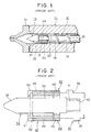
- FIG. 2 shows a longitudinal sectional view of a main portion of another conventional injection unit.
- reference numeral 32 denotes a screw which is disposed rotatably and in an advancingly-retreatively movable manner in an unillustrated heating cylinder.
- the screw 32 includes a metering portion 33 and a screw head 34 disposed at the tip end of the metering portion 33.
- a spiral flight 35 is formed on the surface of the metering portion 33 to thereby form a groove 36 along the flight 35.
- An internal-thread portion 42 is formed at the front end (left-hand end in FIG. 2) of the metering portion 33.
- the screw head 34 includes a conical tip portion 37 formed at its front end, a cylindrical body portion 38 formed at its central section, a seal ring portion 39 formed at its rear section and in the form of a flange integral to the body portion 38, and an external-thread portion 41 formed at its rear end. Through screw-engagement between the external-thread portion 41 and the internal-thread portion 42, the screw head 34 can be fixedly attached to the metering portion 33.
- First resin passageways 45 are formed through the seal ring portion 39 between the front end face of the portion 39 and the rear end face of the portion 39 at a plurality of circumferential positions.
- An annular back-flow prevention ring 43 is disposed around the circumference of the body portion 38 such that the rear end of the ring 43 is in the proximity of or in contact with the front ends of the first resin passageways 45.
- Second resin passageways 46 are formed through the back-flow prevention ring 43 between the front end face of the ring 43 and the rear end face of the ring 43 at a plurality of circumferential positions.
- a pin 51 is disposed through the body portion 38 at a predetermined position so as to stop rotation of the back-flow prevention ring 43, to bring the rear end of the back-flow ring 43 in the proximity of or into contact with the front end of the seal ring portion 39, and to prevent the back-flow ring 43 from coming off the screw head 34.
- Arc engagement grooves 52 are formed in a front end portion of the back-flow prevention ring 43 at positions corresponding to the pin 51, so that both ends of the pin 51 engage the grooves 52.
- Each of the engagement grooves 52 is formed over a predetermined circumferential angle ⁇ .
- the first resin passageways 45 and the second resin passageways 46 are formed such that the passageways 45 are circumferentially shifted from the passageways 46 by the angle ⁇ .
- the ring 43 assumes either a communication position where the first resin passageways 45 and the second resin passageways 46 align with each other to establish communication therebetween or a shutoff position where the communication between the passageways 45 and 46 is broken.
- the screw head 34 is rotated in the same direction as is the screw 32. Accordingly, the seal ring portion 39 and the pin 51 are rotated in the same direction as is the screw 32.
- the back-flow prevention ring 43 remains stationary until the pin 51 abuts end walls of the engagement grooves 52. When the pin 51 abuts the end walls of the engagement grooves 52, the back-flow prevention ring 43 is in the communication position where communication is established between the first resin passageways 45 and the second resin passageways 46. Subsequently, the back-flow prevention ring 43 is rotated in the same direction as is the screw 32.
- the screw 32 is rotated in a reverse direction by a predetermined angle not smaller than the angle ⁇ .
- the screw head 34 is rotated in the same direction as is the screw 32.
- the seal ring portion 39 and the pin 51 are rotated in the same direction as is the screw 32.
- the back-flow prevention ring 43 remains stationary until the pin 51 abuts the other end walls of the engagement grooves 52.
- the back-flow prevention ring 43 is in the shutoff position where the communication between the first resin passageways 45 and the second resin passageways 46 is broken. Subsequently, the back-flow prevention ring 43 is rotated in the same direction as is the screw 32.
- suck-back is performed so as to reduce resin pressure within the space located ahead of the screw head 34, thereby preventing the resin stored in the space from oozing through the tip of an unillustrated injection nozzle.
- resin contained in the metering portion 33 does not move forward, thus preventing variation in resin quantity stored in the space located ahead of the screw head 34.
- the resin stored in the space located ahead of the screw head 34 can be prevented from flowing rearward.
- the quantity of resin to be injected remains constant, thereby preventing molded products from suffering short shot, burrs, or like defects.
- the back-flow prevention ring 43 when the back-flow prevention ring 43 is in the communication position, communication is established between the first resin passageways 45 and the second resin passageways 46; and when the back-flow prevention ring 43 is in the shutoff position, the communication between the passageways 45 and 46 is broken.
- the second resin passageways 46 In order to properly effect the communication/shutoff function, the second resin passageways 46 must be adequately positioned in a circumferential direction with respect to the first resin passageways 45. This positioning can be easily attained through integral formation of the seal ring portion 39 with the body portion 38 and through adequate selection of position of a hole formed in the body portion 38 for receiving the pin 51.
- JP-A-03045325 describes an apparatus in accordance with the preamble of claim 1 for preventing back-flowing in injection-molder.
- a black-flow ring and a screw is releasec for a predetermined angle so as to communicate or block the flow path of a pusher and that of the flow-ring through the rotation of the screw.
- An object of the present invention is to solve the above-mentioned problems in the conventional back-flow prevention apparatus and to provide a back-flow prevention apparatus capable of preventing resin movement associated with suck-back and reducing cost.
- first positioning means for positioning the seal ring at a predetermined position with respect to the screw head.
- second positioning means for establishing communication between the first resin passageway and the second resin passageway when the screw is rotated in the regular direction, for breaking the communication between the first resin passageway and the second resin passageway when the screw is rotated in the reverse direction, and for positioning the back-flow prevention ring with respect to the screw head.
- a metering step when the drive means is activated to rotate the screw in the regular direction, communication is established between the first resin passageway and the second resin passageway. Accordingly, resin contained in the metering portion moves forward through the first and second resin passageways and is then stored in a space located ahead of the screw head.
- the quantity of resin to be injected remains constant, thereby preventing molded products from suffering short shot, burrs, or like defects.
- the resin stored in the space located ahead of the screw head can be prevented from flowing rearward.
- the quantity of resin to be injected remains constant, thereby preventing molded products from suffering short shot, burrs, or like defects.
- seal ring and the screw head can be formed as separate elements, in the case of damage to the seal ring, only the seal ring may be replaced, with no need to replace the entire screw head. Thus, the cost of the back-flow prevention apparatus can be reduced.
- the seal ring and the screw head may be of different materials. This reduces limitations on selection of materials for the seal ring and the screw head, thereby enabling improvement in durability of the seal ring and the screw head as well as cost reduction.
- the screw head is screw-engaged to the metering portion.
- the first positioning means comprises a pin provided through the screw head and an engagement groove formed in the seal ring.
- the second positioning means comprises a protrusion pair formed on the screw head and an engagement protrusion formed on the back-flow prevention ring.
- a fan-shaped groove is formed between the protrusions of the protrusion pair for allowing the engagement protrusion to move within the fan-shaped groove.
- FIG. 3 is a longitudinal sectional view of a main portion of an injection unit according to an embodiment of the present invention
- FIG. 4 is a transverse sectional view of a main portion of the injection unit of the embodiment
- FIG. 5 is an exploded perspective view of a main portion of the injection unit of the embodiment.
- reference numeral 32 denotes a screw which is disposed rotatably and in an advancingly-retreatively movable manner in an unillustrated heating cylinder.
- the screw 32 includes a metering portion 33 and a screw head 64 disposed at the tip end of the metering portion 33.
- a spiral flight 35 is formed on the surface of the metering portion 33 to thereby form a groove 36 along the flight 35.
- An internal-thread portion 42 is formed at the front end (left-hand end in FIG. 3) of the metering portion 33.
- the screw head 64 includes a conical tip portion 67 formed at its front end, a cylindrical body portion 68 formed at its central section, a small-diameter engagement portion 69 formed at its rear section, and an external-thread portion 71 formed at its rear end.
- An annular seal ring 70 is removably disposed around the circumference of the engagement portion 69.
- two engagement grooves 74 are formed in the inner circumferential surface of the seal ring 70.
- a pin 72 is disposed through the engagement portion 69 such that both ends of the pin 72 engage the corresponding engagement grooves 74.
- First resin passageways 73 are formed through the seal ring 70 between the front end face of the ring 70 and the rear end face of the ring 70 at a plurality of circumferential positions.
- An annular back-flow prevention ring 43 is disposed around the circumference of the body portion 68 such that the rear end (right-hand end in FIG. 3) of the ring 43 is in the proximity of or in contact with the front end of the seal ring 70.
- Second resin passageways 46 are formed through the back-flow prevention ring 43 between the front end face of the ring 43 and the rear end face of the ring 43 at a plurality of circumferential positions.
- protrusion pairs 75 are formed on the body portion 68 at a plurality of circumferential positions such that a fan-shaped groove 78 is formed between protrusions 75a and 75b of each protrusion pair 75.
- Arc engagement protrusions 76 corresponding to the protrusion pairs 75 are formed at a front end portion of the back-flow prevention ring 43 so as to engage the corresponding fan-shaped grooves 78.
- Each of the fan-shaped grooves 78 is formed over a predetermined circumferential angle ⁇ .
- the engagement protrusions 76 move within the corresponding fan-shaped grooves 78, the screw head 64 and the back-flow prevention ring 43 rotate relative to each other by the angle ⁇ .
- the first and second resin passageways 73 and 46 are circumferentially shifted from each other by an angle of up to ⁇ .
- the ring 43 assumes either a communication position where the first resin passageways 73 and the second resin passageways 46 align with each other to establish communication therebetween or a shutoff position where the communication between the passageways 73 and 46 is broken.
- the back-flow prevention ring 43 When the engagement protrusions 76 abut the protrusions 75a, the back-flow prevention ring 43 is in the communication position where communication is established between the first resin passageways 73 and the second resin passageways 46. Subsequently, the back-flow prevention ring 43 is rotated in the same direction as is the screw 32.
- the back-flow prevention ring 43 When the engagement protrusions 76 abut the other protrusions 75b, the back-flow prevention ring 43 is in the shutoff position where the communication between the first resin passageways 73 and the second resin passageways 46 is broken. Subsequently, the back-flow prevention ring 43 is rotated in the same direction as is the screw 32.
- suck-back is performed so as to reduce resin pressure within the space located ahead of the screw head 64, thereby preventing the resin stored in the space from oozing through the tip of an unillustrated injection nozzle.
- resin contained in the metering portion 33 does not move forward, thus preventing variation in resin quantity stored in the space located ahead of the screw head 64.
- the drive means holds the screw 32 in a metering-step completion position within the heating cylinder.
- the resin stored in the space located ahead of the screw head 64 can be prevented from flowing rearward.
- the quantity of resin to be injected remains constant, thereby preventing molded products from suffering short shot, burrs, or like defects.
- the back-flow prevention ring 43 when the back-flow prevention ring 43 is in the communication position, communication is established between the first resin passageways 73 and the second resin passageways 46; and when the back-flow prevention ring 43 is in the shutoff position, the communication between the passageways 73 and 46 is broken.
- the second resin passageways 46 In order to properly effect the communication/shutoff function, the second resin passageways 46 must be adequately positioned in a circumferential direction with respect to the first resin passageways 73.
- This positioning can be easily attained through formation of the protrusion pairs 75 on the body portion 68 at predetermined positions so as to establish the engagement between the fan-shaped grooves 78 and the corresponding engagement protrusions 76 of the back-flow prevention ring 43 to thereby adequately position the back-flow prevention ring 43 with respect to the screw head 64 and through the engagement between both ends of the pin 72 and the engagement grooves 74 to thereby adequately position the seal ring 70 with respect to the screw head 64.
- the pin 72 and the engagement grooves 74 serve as the first positioning means of the invention.
- the protrusion pairs 75 and the engagement protrusions 76 serve as the second positioning means of the invention.
- the second resin passageways 46 can be readily and adequately positioned with respect to the first resin passageways 73.
- seal ring 70 and the body portion 68 can be formed as separate elements, in the case of damage to the seal ring 70, only the seal ring 70 may be replaced, with no need to replace the entire screw head 64. Thus, the cost of the back-flow prevention apparatus can be reduced.
- seal ring 70 and the screw head 64 may be of different materials. This reduces limitations on selection of materials for the seal ring 70 and the screw head 64, thereby enabling improvement in durability of the seal ring 70 and the screw head 64 as well as cost reduction.
Landscapes
- Manufacturing & Machinery (AREA)
- Mechanical Engineering (AREA)
- Engineering & Computer Science (AREA)
- Injection Moulding Of Plastics Or The Like (AREA)
- Structure Of Belt Conveyors (AREA)
- Magnetic Resonance Imaging Apparatus (AREA)
- Pinball Game Machines (AREA)
- External Artificial Organs (AREA)
- Paper (AREA)
- Confectionery (AREA)
- Undergarments, Swaddling Clothes, Handkerchiefs Or Underwear Materials (AREA)
- Push-Button Switches (AREA)
- Seal Device For Vehicle (AREA)
Claims (5)
- Appareil anti-retour comprenant :a) une vis (32) qui comprend une partie de dosage (33) et une tête de vis (64) ;b) une bague anti-retour (43) qui est installée sur une partie avant de- ladite tête de vis (64) de façon à être rotative par rapport à ladite bague d'étanchéité (70) et dans laquelle est formé un premier passage de résine (46) ; etc) un moyen d'entraínement pour faire tourner sélectivement ladite vis dans un sens normal et dans un sens inverse ;
caractérisé en ce qued) une bague d'étanchéité (70) est installée de façon amovible sur une partie arrière de ladite tête de vis (64) qui présente un premier passage de résine (73) formé à l'intérieur ;e) un premier moyen de positionnement est disposé entre ladite tête de vis (64) et ladite bague d'étanchéité (70) et il est adapté pour positionner ladite bague d'étanchéité (70) dans une position prédéterminée par rapport à ladite tête de vis (64) etf) un deuxième moyen de positionnement est disposé entre ladite tête de vis (64) et ladite bague anti-retour (43) et il est adapté pour établir la communication entre ledit premier passage de résine (73) et ledit deuxième passage de résine (46) lorsque ladite vis (32) tourne dans le sens normal afin d'interrompre la communication entre ledit premier passage de résine (73) et ledit deuxième passage de résine (46) lorsque ladite vis (32) tourne en sens inverse et pour positionner ladite bague anti-retour (43) par rapport à ladite tête de vis (64). - Appareil anti-retour selon la revendication 1, dans lequel ladite tête de vis (64) est vissée dans ladite partie de dosage (33).
- Appareil anti-retour selon la revendication 1, dans lequel ledit premier moyen de positionnement comprend une goupille (72) prévue à travers ladite tête de vis (64) et une rainure de prise (74) formée dans ladite bague d'étanchéité (70).
- Appareil anti-retour selon la revendication 1, dans lequel ledit deuxième moyen de positionnement comprend une paire de protubérances (75) formée sur ladite tête de vis (64) et une protubérance de prise (76) formée sur ladite bague anti-retour (43).
- Appareil anti-retour selon la revendication 4, dans lequel une rainure en forme d'éventail (78) est formée entre les protubérances (75a, 75b) de ladite paire de protubérances (75) afin de permettre aux dites protubérances de prise (76) de se déplacer à l'intérieur de ladite rainure en forme d'éventail (78).
Applications Claiming Priority (3)
| Application Number | Priority Date | Filing Date | Title |
|---|---|---|---|
| JP19373997A JP3877190B2 (ja) | 1997-07-18 | 1997-07-18 | 逆流防止装置 |
| JP193739/97 | 1997-07-18 | ||
| JP19373997 | 1997-07-18 |
Publications (2)
| Publication Number | Publication Date |
|---|---|
| EP0893227A1 EP0893227A1 (fr) | 1999-01-27 |
| EP0893227B1 true EP0893227B1 (fr) | 2002-05-15 |
Family
ID=16313014
Family Applications (1)
| Application Number | Title | Priority Date | Filing Date |
|---|---|---|---|
| EP98113206A Expired - Lifetime EP0893227B1 (fr) | 1997-07-18 | 1998-07-15 | Dispositif antiretour |
Country Status (9)
| Country | Link |
|---|---|
| US (1) | US6007322A (fr) |
| EP (1) | EP0893227B1 (fr) |
| JP (1) | JP3877190B2 (fr) |
| KR (1) | KR100284012B1 (fr) |
| CN (1) | CN1077493C (fr) |
| AT (1) | ATE217570T1 (fr) |
| DE (1) | DE69805367T2 (fr) |
| SG (1) | SG71813A1 (fr) |
| TW (1) | TW450219U (fr) |
Families Citing this family (19)
| Publication number | Priority date | Publication date | Assignee | Title |
|---|---|---|---|---|
| JP3299235B2 (ja) * | 1999-11-12 | 2002-07-08 | 住友重機械工業株式会社 | 逆流防止装置及び射出装置の運転方法 |
| DE19959495C1 (de) * | 1999-12-10 | 2001-05-23 | Battenfeld Gmbh | Rückstromsperre |
| JP3509791B2 (ja) * | 2001-07-31 | 2004-03-22 | 一郎 大島 | インラインスクリュー型射出成形機の逆流防止装置 |
| DE10230041B4 (de) * | 2002-07-04 | 2006-04-20 | Johann Holzschuh | Rückstromsperre |
| DE10239929B4 (de) * | 2002-08-30 | 2008-05-08 | Johann Holzschuh | Rückstromsperre mit steuerbarem Verschluss |
| JP3652681B2 (ja) * | 2002-11-08 | 2005-05-25 | ファナック株式会社 | 射出成形機における計量方法及び制御装置 |
| KR20050100636A (ko) * | 2003-01-27 | 2005-10-19 | 커뮤니티 엔터프라이즈, 엘엘씨. | 사출성형기계의 정화효과 최대화 장치 및 방법 |
| JP4050644B2 (ja) * | 2003-03-27 | 2008-02-20 | 株式会社日本製鋼所 | インラインスクリュ式可塑化射出装置 |
| US7104775B2 (en) * | 2003-03-27 | 2006-09-12 | Lg Cable Ltd. | Injection unit having rotatable device for preventing reverse flow |
| CN1822942B (zh) * | 2003-07-17 | 2010-09-22 | 住友重机械工业株式会社 | 成形方法、清理方法以及成形机 |
| JP4434715B2 (ja) * | 2003-12-12 | 2010-03-17 | 東芝機械株式会社 | スクリュの逆流防止装置 |
| CA2463281C (fr) * | 2004-04-05 | 2007-11-13 | Husky Injection Molding Systems Ltd. | Clapet de non retour pour systeme de moulage |
| US7284978B2 (en) * | 2005-06-30 | 2007-10-23 | Husky Injection Molding Systems Ltd. | Brake for molding machine valve |
| US20070065538A1 (en) * | 2005-09-16 | 2007-03-22 | Husky Injection Molding Systems Ltd. | Molding system having valve including pump |
| CN101954726A (zh) * | 2010-08-31 | 2011-01-26 | 佛山市顺德区震德塑料机械有限公司 | 用于注塑机的注射装置 |
| TW201341156A (zh) * | 2012-04-10 | 2013-10-16 | Foxnum Technology Co Ltd | 防逆流裝置 |
| CN108698287B (zh) * | 2015-12-04 | 2020-02-18 | 挤压满公司 | 模塑机和模塑零件的方法 |
| CN107553843B (zh) * | 2017-10-13 | 2019-07-02 | 宁波华优汽车零部件有限公司 | 一种注塑挤出头旋转式防逆装置 |
| CN112536995B (zh) * | 2020-11-19 | 2022-09-06 | 佛山市南海区百兴玩具有限公司 | 一种工件生产用模具进胶装置 |
Family Cites Families (6)
| Publication number | Priority date | Publication date | Assignee | Title |
|---|---|---|---|---|
| DE2215585A1 (de) * | 1972-03-30 | 1973-10-31 | Rolf Deerberg | Einrichtung zum spritzen von duroplastischen werkstoffen |
| US4643665A (en) * | 1985-09-05 | 1987-02-17 | Mallard Machine Company | Check valve assembly for injection molding machine |
| JPH0345325A (ja) * | 1989-07-14 | 1991-02-26 | Japan Steel Works Ltd:The | 射出成形機の逆流防止装置および逆流防止方法 |
| US5112213A (en) * | 1991-02-26 | 1992-05-12 | Van Dorn Company | Driven ring-type non-return valve for injection molding |
| JP3045325B2 (ja) * | 1991-03-17 | 2000-05-29 | ソニー株式会社 | 磁気記録再生装置 |
| JP2880676B2 (ja) * | 1995-12-26 | 1999-04-12 | 住友重機械工業株式会社 | 逆流防止装置 |
-
1997
- 1997-07-18 JP JP19373997A patent/JP3877190B2/ja not_active Expired - Lifetime
-
1998
- 1998-06-29 US US09/106,108 patent/US6007322A/en not_active Expired - Lifetime
- 1998-07-01 SG SG1998001568A patent/SG71813A1/en unknown
- 1998-07-01 TW TW089207381U patent/TW450219U/zh not_active IP Right Cessation
- 1998-07-15 AT AT98113206T patent/ATE217570T1/de active
- 1998-07-15 EP EP98113206A patent/EP0893227B1/fr not_active Expired - Lifetime
- 1998-07-15 KR KR1019980028569A patent/KR100284012B1/ko not_active Expired - Fee Related
- 1998-07-15 CN CN98103023A patent/CN1077493C/zh not_active Expired - Lifetime
- 1998-07-15 DE DE69805367T patent/DE69805367T2/de not_active Expired - Lifetime
Also Published As
| Publication number | Publication date |
|---|---|
| ATE217570T1 (de) | 2002-06-15 |
| SG71813A1 (en) | 2000-04-18 |
| CN1209382A (zh) | 1999-03-03 |
| JP3877190B2 (ja) | 2007-02-07 |
| KR19990013882A (ko) | 1999-02-25 |
| CN1077493C (zh) | 2002-01-09 |
| EP0893227A1 (fr) | 1999-01-27 |
| US6007322A (en) | 1999-12-28 |
| TW450219U (en) | 2001-08-11 |
| JPH1134128A (ja) | 1999-02-09 |
| KR100284012B1 (ko) | 2001-04-02 |
| DE69805367D1 (de) | 2002-06-20 |
| DE69805367T2 (de) | 2002-10-10 |
Similar Documents
| Publication | Publication Date | Title |
|---|---|---|
| EP0893227B1 (fr) | Dispositif antiretour | |
| EP1101591B1 (fr) | Barrage antireflux à la tête de vis de machines d'injection à vis | |
| JPH06339962A (ja) | 射出成形装置 | |
| US7934923B2 (en) | Screw, injection apparatus, and pressure member | |
| JPS6219423A (ja) | 射出成形機 | |
| JP3483748B2 (ja) | プリプラ式射出装置 | |
| JPH09207180A (ja) | スクリュプリプラ式射出装置 | |
| JP2626830B2 (ja) | 樹脂成形スクリュ用逆止リング | |
| JPH1190967A (ja) | 逆流防止装置 | |
| JP3345360B2 (ja) | 射出装置 | |
| JP2612069B2 (ja) | 射出成形機のシール機構 | |
| JP3220653B2 (ja) | 逆流防止装置 | |
| JP3516853B2 (ja) | プリプラ式射出装置 | |
| JP2612087B2 (ja) | 射出成形機 | |
| US6345976B1 (en) | Injection apparatus | |
| JP3127391B2 (ja) | プリプラ式射出成形機及びその制御方法 | |
| JPH11105088A (ja) | プリプラ式射出装置 | |
| JP2000117776A (ja) | 射出ノズル | |
| JP3345366B2 (ja) | 射出装置及びその射出方法 | |
| JP2001030318A (ja) | 射出装置 | |
| JP3359142B2 (ja) | 射出成形機におけるチェックリングの開閉装置 | |
| JP3312014B2 (ja) | 射出装置及び射出ノズル | |
| JP2000309043A (ja) | 逆流防止装置 | |
| JP2004017450A (ja) | 射出装置 | |
| JP2000218665A (ja) | スクリュ式射出成形装置 |
Legal Events
| Date | Code | Title | Description |
|---|---|---|---|
| PUAI | Public reference made under article 153(3) epc to a published international application that has entered the european phase |
Free format text: ORIGINAL CODE: 0009012 |
|
| AK | Designated contracting states |
Kind code of ref document: A1 Designated state(s): AT CH DE FR GB LI NL |
|
| AX | Request for extension of the european patent |
Free format text: AL;LT;LV;MK;RO;SI |
|
| 17P | Request for examination filed |
Effective date: 19990129 |
|
| AKX | Designation fees paid |
Free format text: AT CH DE FR GB LI NL |
|
| 17Q | First examination report despatched |
Effective date: 20000816 |
|
| GRAG | Despatch of communication of intention to grant |
Free format text: ORIGINAL CODE: EPIDOS AGRA |
|
| GRAG | Despatch of communication of intention to grant |
Free format text: ORIGINAL CODE: EPIDOS AGRA |
|
| GRAG | Despatch of communication of intention to grant |
Free format text: ORIGINAL CODE: EPIDOS AGRA |
|
| GRAH | Despatch of communication of intention to grant a patent |
Free format text: ORIGINAL CODE: EPIDOS IGRA |
|
| GRAH | Despatch of communication of intention to grant a patent |
Free format text: ORIGINAL CODE: EPIDOS IGRA |
|
| GRAA | (expected) grant |
Free format text: ORIGINAL CODE: 0009210 |
|
| AK | Designated contracting states |
Kind code of ref document: B1 Designated state(s): AT CH DE FR GB LI NL |
|
| REF | Corresponds to: |
Ref document number: 217570 Country of ref document: AT Date of ref document: 20020615 Kind code of ref document: T |
|
| REG | Reference to a national code |
Ref country code: GB Ref legal event code: FG4D Ref country code: CH Ref legal event code: EP |
|
| REG | Reference to a national code |
Ref country code: CH Ref legal event code: NV Representative=s name: E. BLUM & CO. PATENTANWAELTE |
|
| REF | Corresponds to: |
Ref document number: 69805367 Country of ref document: DE Date of ref document: 20020620 |
|
| ET | Fr: translation filed | ||
| PLBE | No opposition filed within time limit |
Free format text: ORIGINAL CODE: 0009261 |
|
| STAA | Information on the status of an ep patent application or granted ep patent |
Free format text: STATUS: NO OPPOSITION FILED WITHIN TIME LIMIT |
|
| 26N | No opposition filed |
Effective date: 20030218 |
|
| REG | Reference to a national code |
Ref country code: CH Ref legal event code: PFA Owner name: SUMITOMO HEAVY INDUSTRIES, LTD. Free format text: SUMITOMO HEAVY INDUSTRIES, LTD.#9-11, KITASHINAGAWA 5-CHOME#SHINAGAWA-KU, TOKYO 141-0001 (JP) -TRANSFER TO- SUMITOMO HEAVY INDUSTRIES, LTD.#9-11, KITASHINAGAWA 5-CHOME#SHINAGAWA-KU, TOKYO 141-0001 (JP) |
|
| PGFP | Annual fee paid to national office [announced via postgrant information from national office to epo] |
Ref country code: GB Payment date: 20120711 Year of fee payment: 15 |
|
| PGFP | Annual fee paid to national office [announced via postgrant information from national office to epo] |
Ref country code: NL Payment date: 20120714 Year of fee payment: 15 |
|
| PGFP | Annual fee paid to national office [announced via postgrant information from national office to epo] |
Ref country code: CH Payment date: 20130712 Year of fee payment: 16 |
|
| REG | Reference to a national code |
Ref country code: NL Ref legal event code: V1 Effective date: 20140201 |
|
| GBPC | Gb: european patent ceased through non-payment of renewal fee |
Effective date: 20130715 |
|
| PG25 | Lapsed in a contracting state [announced via postgrant information from national office to epo] |
Ref country code: GB Free format text: LAPSE BECAUSE OF NON-PAYMENT OF DUE FEES Effective date: 20130715 Ref country code: NL Free format text: LAPSE BECAUSE OF NON-PAYMENT OF DUE FEES Effective date: 20140201 |
|
| PGFP | Annual fee paid to national office [announced via postgrant information from national office to epo] |
Ref country code: AT Payment date: 20140626 Year of fee payment: 17 Ref country code: FR Payment date: 20140708 Year of fee payment: 17 |
|
| REG | Reference to a national code |
Ref country code: CH Ref legal event code: PL |
|
| PG25 | Lapsed in a contracting state [announced via postgrant information from national office to epo] |
Ref country code: CH Free format text: LAPSE BECAUSE OF NON-PAYMENT OF DUE FEES Effective date: 20140731 Ref country code: LI Free format text: LAPSE BECAUSE OF NON-PAYMENT OF DUE FEES Effective date: 20140731 |
|
| REG | Reference to a national code |
Ref country code: AT Ref legal event code: MM01 Ref document number: 217570 Country of ref document: AT Kind code of ref document: T Effective date: 20150715 |
|
| REG | Reference to a national code |
Ref country code: FR Ref legal event code: ST Effective date: 20160331 |
|
| PG25 | Lapsed in a contracting state [announced via postgrant information from national office to epo] |
Ref country code: FR Free format text: LAPSE BECAUSE OF NON-PAYMENT OF DUE FEES Effective date: 20150731 Ref country code: AT Free format text: LAPSE BECAUSE OF NON-PAYMENT OF DUE FEES Effective date: 20150715 |
|
| PGFP | Annual fee paid to national office [announced via postgrant information from national office to epo] |
Ref country code: DE Payment date: 20170711 Year of fee payment: 20 |
|
| REG | Reference to a national code |
Ref country code: DE Ref legal event code: R071 Ref document number: 69805367 Country of ref document: DE |