EP0893264A2 - Tête d'impression à jet d'encre contenant un liquide spécifique d'amorçage et de revêtement - Google Patents
Tête d'impression à jet d'encre contenant un liquide spécifique d'amorçage et de revêtement Download PDFInfo
- Publication number
- EP0893264A2 EP0893264A2 EP98303578A EP98303578A EP0893264A2 EP 0893264 A2 EP0893264 A2 EP 0893264A2 EP 98303578 A EP98303578 A EP 98303578A EP 98303578 A EP98303578 A EP 98303578A EP 0893264 A2 EP0893264 A2 EP 0893264A2
- Authority
- EP
- European Patent Office
- Prior art keywords
- channels
- ink
- nozzles
- priming
- printhead
- Prior art date
- Legal status (The legal status is an assumption and is not a legal conclusion. Google has not performed a legal analysis and makes no representation as to the accuracy of the status listed.)
- Withdrawn
Links
- 238000000576 coating method Methods 0.000 title claims abstract description 63
- 239000012530 fluid Substances 0.000 title claims abstract description 63
- 239000011248 coating agent Substances 0.000 title claims abstract description 62
- 230000037452 priming Effects 0.000 title claims abstract description 58
- 238000009736 wetting Methods 0.000 claims abstract description 39
- 230000002209 hydrophobic effect Effects 0.000 claims abstract description 8
- BDERNNFJNOPAEC-UHFFFAOYSA-N propan-1-ol Chemical group CCCO BDERNNFJNOPAEC-UHFFFAOYSA-N 0.000 claims description 20
- PEDCQBHIVMGVHV-UHFFFAOYSA-N glycerol group Chemical group OCC(O)CO PEDCQBHIVMGVHV-UHFFFAOYSA-N 0.000 claims description 13
- XLYOFNOQVPJJNP-UHFFFAOYSA-N water Substances O XLYOFNOQVPJJNP-UHFFFAOYSA-N 0.000 claims description 10
- 238000001035 drying Methods 0.000 claims description 7
- 239000000758 substrate Substances 0.000 claims description 4
- IEORSVTYLWZQJQ-UHFFFAOYSA-N 2-(2-nonylphenoxy)ethanol Chemical compound CCCCCCCCCC1=CC=CC=C1OCCO IEORSVTYLWZQJQ-UHFFFAOYSA-N 0.000 claims description 3
- IAYPIBMASNFSPL-UHFFFAOYSA-N Ethylene oxide Chemical compound C1CO1 IAYPIBMASNFSPL-UHFFFAOYSA-N 0.000 claims description 3
- 229920006158 high molecular weight polymer Polymers 0.000 claims description 3
- 229920000847 nonoxynol Polymers 0.000 claims description 3
- -1 alkyl quaternary ammonium chloride Chemical compound 0.000 claims description 2
- 239000004094 surface-active agent Substances 0.000 claims 1
- 239000000976 ink Substances 0.000 description 97
- KFZMGEQAYNKOFK-UHFFFAOYSA-N Isopropanol Chemical compound CC(C)O KFZMGEQAYNKOFK-UHFFFAOYSA-N 0.000 description 18
- 239000007788 liquid Substances 0.000 description 10
- 238000012423 maintenance Methods 0.000 description 7
- 238000003860 storage Methods 0.000 description 7
- 238000010438 heat treatment Methods 0.000 description 5
- 238000003491 array Methods 0.000 description 4
- 238000004140 cleaning Methods 0.000 description 4
- 229960005150 glycerol Drugs 0.000 description 4
- 239000000203 mixture Substances 0.000 description 4
- 239000002736 nonionic surfactant Substances 0.000 description 3
- GPRLSGONYQIRFK-MNYXATJNSA-N triton Chemical compound [3H+] GPRLSGONYQIRFK-MNYXATJNSA-N 0.000 description 3
- 230000000694 effects Effects 0.000 description 2
- 238000004519 manufacturing process Methods 0.000 description 2
- 238000000034 method Methods 0.000 description 2
- 238000007789 sealing Methods 0.000 description 2
- 235000011449 Rosa Nutrition 0.000 description 1
- 230000009471 action Effects 0.000 description 1
- 230000000712 assembly Effects 0.000 description 1
- 238000000429 assembly Methods 0.000 description 1
- 239000003093 cationic surfactant Substances 0.000 description 1
- 230000008859 change Effects 0.000 description 1
- 239000003086 colorant Substances 0.000 description 1
- 239000002173 cutting fluid Substances 0.000 description 1
- 239000000645 desinfectant Substances 0.000 description 1
- 230000007774 longterm Effects 0.000 description 1
- 239000000314 lubricant Substances 0.000 description 1
- 238000005461 lubrication Methods 0.000 description 1
- 230000007246 mechanism Effects 0.000 description 1
- 229910052751 metal Inorganic materials 0.000 description 1
- 239000002184 metal Substances 0.000 description 1
- 150000002739 metals Chemical class 0.000 description 1
- 239000003973 paint Substances 0.000 description 1
- 229920000570 polyether Polymers 0.000 description 1
- 230000002035 prolonged effect Effects 0.000 description 1
- 230000009467 reduction Effects 0.000 description 1
- 239000002904 solvent Substances 0.000 description 1
- 239000000126 substance Substances 0.000 description 1
- 238000009834 vaporization Methods 0.000 description 1
- 230000008016 vaporization Effects 0.000 description 1
- 239000000080 wetting agent Substances 0.000 description 1
Images

Classifications
-
- B—PERFORMING OPERATIONS; TRANSPORTING
- B41—PRINTING; LINING MACHINES; TYPEWRITERS; STAMPS
- B41J—TYPEWRITERS; SELECTIVE PRINTING MECHANISMS, i.e. MECHANISMS PRINTING OTHERWISE THAN FROM A FORME; CORRECTION OF TYPOGRAPHICAL ERRORS
- B41J2/00—Typewriters or selective printing mechanisms characterised by the printing or marking process for which they are designed
- B41J2/005—Typewriters or selective printing mechanisms characterised by the printing or marking process for which they are designed characterised by bringing liquid or particles selectively into contact with a printing material
- B41J2/01—Ink jet
- B41J2/17—Ink jet characterised by ink handling
- B41J2/1707—Conditioning of the inside of ink supply circuits, e.g. flushing during start-up or shut-down
Definitions
- the present invention relates generally to liquid ink printers or recording apparatus and more particularly relates to an ink jet printhead for use in such a recording apparatus.
- the printhead is charged or filled with a non-ink priming and coating fluid prior to a first time filling or charging of the printhead with printing ink.
- Liquid ink printers such as inkjet printers are well known, and include the type frequently referred to as continuous stream or as drop-on-demand printers, and use piezoelectric, acoustic, phase change wax-based or thermal energy ink release techniques.
- Each such printer has at least one printhead that when filled or charged with ink, is then controllable to direct droplets of ink towards a recording sheet for printing.
- the charged ink is contained in a plurality of channels that are individually connected to ink ejecting and directing nozzles. Power pulses cause the droplets of ink to be expelled or ejected as required from the nozzles.
- the power pulses are usually produced by heatable resistors, each located in a respective one of the channels, and each individually capable of being powered to heat and vaporize ink in the channels.
- a vapor bubble grows in the associated channel and initially bulges from the channel orifice or nozzle, followed by collapse of the bubble.
- the ink within the channel then retracts and separates from the bulging ink thereby forming a droplet moving in a direction away from the nozzle, and towards the recording medium or sheet.
- a print dot or spot of ink having a desired size and shape for quality printing is deposited on the recording medium.
- the channel is then refilled by capillary action, which, in turn, draws ink from a supply container of liquid ink. Operation of a thermal ink-jet printer is described in, for example, U.S. Patent No. 4,849,774.
- both the channels and nozzles In order for the droplets of ink ejected as above to have the desired size and shape, both the channels and nozzles must be fully wetted or coated with ink and primed, prior to droplet ejection. In other words, the surfaces of the walls of both the channels and nozzles must be prepared for encouraging and enabling desired ink flow therethrough.
- Such wetting or coating and priming of the channels and nozzles is usually carried out as a first time ink prime or priming of a printhead structure after manufacturing of such structure. It is also usual to rewet and reprime such channels and nozzles as ongoing maintenance activities, following prolonged idle periods of the ink jet printer. Post-idle period priming activities are well known, and are usually carried out mechanically, for example, with a capping and vacuum suction maintenance apparatus within the printer.
- a successful first time ink wetting and priming of a printhead structure is usually the more difficult to achieve. It has been found that this is due in significant part to a type of hydrophobic filming that tends to grow on, or form on the surfaces of the walls of the channels and nozzles, particularly on the surface of brand new and unused printhead structures.
- the difficulty is also due to a relatively low wetting ability of preferred quality printing inks which each tend to have a desired but relatively high surface tension of such inks. Such relatively high surface tension and resulting low wetting ability, are required in such inks in order for the inks to have acceptably controllable image forming qualities.
- the difficulty of a first time wetting and priming of a printhead structure is further exacerbated or aggravated in cases, where after manufacture of the printhead structure, it is stored or shipped over an extended period of time, usually in a dry state or not charged with ink.
- Such a printhead structure usually can be stored or shipped as such by itself, or assembled onto an ink jet printer.
- the difficulty of a first time wetting and priming of printhead structures is even worse if the printhead structure is that of a full width array (FWA) printhead having 4000+ (four thousand and more) channels and nozzles that must be fully and successfully wetted and primed with ink for the first time, after such extended storage or shipping.
- FWA full width array
- an ink jet printhead for use in an ink jet printer, or mounted in an ink jet printer being shipped or being stored.
- the ink jet printhead comprises a printhead structure having a body including walls having surfaces defining fluid flow channels, and fluid ejecting nozzles at the ends of the channels.
- the channels and the nozzles are filled with a non-ink priming and coating fluid prior to a first time filling thereof with printing ink.
- the non-ink priming and coating fluid has low surface tension and volatility characteristics for enabling the non-ink priming and coating fluid to spontaneously and quickly move through the channels of the printhead and into the nozzles thereof.
- the non-ink priming and coating fluid also has surface treating characteristics for wetting and coating the surfaces of the walls of the channels and nozzles in order to clean and lubricate such surfaces, thereby destroying any hydrophobic film on such surfaces, and enabling a subsequent successful first time wetting and priming of the channels and nozzles with printing ink.
- the essential components of the printing apparatus 10 include a motor 11 connected to a suitable power supply (not shown) and arranged with an output shaft 14 parallel to an axis 15 of a cylindrical drum 16 which is supported for rotation on bearings (not shown).
- a pulley 17 permits direct engagement of the output shaft 14, to a drive belt 18 for enabling the drum 16 to be continuously rotationally driven by the motor 11 in the direction of an arrow AA at a predetermined rotational speed.
- a recording medium such as a sheet of paper or a transparency (not shown since the printer 10 as shown is as in storage or in shipping transit), will in operation be placed over an outer surface 20 of the drum 16, with its leading edge attached to the surface 20.
- the sheet is attached to the drum either through the application of a vacuum, through holes in the drum 16 (not shown), or through other means of holding the sheet to the drum, for example, electrostatic means.
- electrostatic means In operation, as the drum 16 with a sheet attached thereto rotates, it will move the sheet with it past a printhead carriage 22.
- the printhead carriage 22 is supported for example by a lead screw 24 that is mounted so that its axis is parallel to the axis 15 of the drum 16. Additionally, it is supported by fixed bearings (not shown) which enable it (the carriage 22) to be capable of slidably translating axially.
- a carriage rail 23 provides further support for the carriage 22 as it moves in the direction of arrow 25, that is perpendicular to the moving direction of the sheet.
- the printer 10 includes printhead partial width arrays 32 that are each filled or charged with the non-ink priming and coating fluid 60 of the present invention, prior to a first time wetting and priming thereof with printing ink.
- the printhead partial width arrays 32 comprise a first partial width array printbar 32A, a second partial width array printbar 32B, a third partial width array printbar 32C, and a fourth partial width array printbar 32D.
- Each printbar 32A-32D as shown includes at least a printhead 34, or as preferred here, two printheads, a first printhead die 34 and a second printhead die 36 that are butted together to form such printbar.
- each of the printheads 34 and 36 includes several hundred or more channels and nozzles which in operation can be fired sequentially.
- the partial width arrays 32 when charged or filled with ink, can be moved in the direction of arrow 25 for printing on the sheet.
- the first, second and third partial width array printbars 32A-32C respectively, will each contain ink of one of the colors cyan, magenta or yellow, for color printing.
- the fourth partial width array printbar 32D will contain black ink when necessary, especially when needed for printing graphics.
- each of the partial width array printbars 32A-32C is preferably filled with the non-ink priming and coating fluid of the present invention, while in storage, during shipping, or prior to filling with ink.
- the printer 10 also includes a full-width array or pagewidth printbar 40 that is also filled or charged with the non-ink priming and coating fluid 60 of the present invention, prior to a first time wetting and priming thereof with printing ink.
- the pagewidth printbar 40 is supported by an appropriate support structure (not shown) above the drum 16 for printing on the recording medium when filled or charged with printing ink.
- the pagewidth printbar 40 has a length sufficient to print across the entire width (or length) of the recording medium during a single pass of the recording medium beneath the printbar.
- the printbar 40 as shown includes a plurality of printhead units 42 that are affixed to a supporting substrate (not shown) in an abutted fashion. Alternatively, individual printhead units 42 may be spaced from one another by a distance approximately equal to the length of a single printhead subunit and bonded to opposing surfaces of the supporting substrate.
- each printhead unit 34, 36 and 42 contains liquid droplet ejecting orifices or nozzles 62 which can in operation, eject ink droplets along a trajectory 45 (FIG. 1), which is substantially perpendicular to the surface of a recording medium.
- each printhead contains heating elements 46, and printed wiring boards (not shown).
- the printed wiring boards contain circuitry required to interface and cause the individual heating elements 46 in the printhead units to eject liquid (e.g. ink) droplets from the nozzles 62. While not shown, the printed wiring boards are connected to individual contacts contained on the printhead units via a commonly known wire bonding technique.
- the data required to drive the individual heating elements 46 is supplied from an external system by a standard printer interface, modified and/or buffered by a printer micro processor (not shown) within the printer.
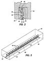
- such a printhead for example, includes a tube 49 through which a fluid, such as ink or the non-ink priming and coating fluid 60 of the present invention, is introduced into manifold 48. Such fluid is then conducted from the manifold 48 into a plurality of channels shown as 44.
- Each of the channels 44 of the printhead includes a heating element 46.
- the energy of the signal causes heat to be generated in the channel 44.
- the heat causes vaporization of fluid or liquid such as ink in the channel 44, and the liquid in the channel 44 is pushed outwards through the corresponding nozzle 62 in the form of a droplet.
- the channel 44 is replenished from the manifold 48.
- a full width or pagewidth array printhead such as 40 (FIG. 1) includes a linear array of channels 44 (only portions thereof adjoining nozzles 62 are shown) and the corresponding nozzles 62. (In both FIGS. 2 and 3, the size of the channels 44 and nozzles 62, relative to the rest of the apparatus, have been significantly exaggerated.)
- all external openings into the channels such as the external side of the nozzles 62, preferably will be sealed, for example, with a removable sealing device 64.
- the non-ink priming and coating fluid 60 of the present invention is preferably a fluid having low surface tension and volatility characteristics for enabling the non-ink priming and coating fluid to spontaneously and quickly move through the channels of the printhead and into the nozzles thereof, as well as surface treating characteristics for wetting and coating the surfaces of the walls of the channels and nozzles.
- Wetting and coating the surfaces of the walls of the channels and nozzles as such advantageously cleans and lubricates such surfaces, thereby destroying any hydrophobic film on such surfaces and enabling a successful first time wetting and priming of the channels and nozzles with printing ink.
- the non-ink priming and coating fluid 60 can equally be a mixture of fluids comprising a transport or carrier component that has a relatively low surface tension for providing the low surface tension and volatility characteristics of the fluid or mixture.
- the non-ink priming and coating fluid will include at least one surface wetting or coating component that leaves a hydrophilic coating on the surfaces of the walls of the channels and nozzles.
- Such a hydrophilic coating can be a temporary wetting of the surfaces for preventing such surfaces from rapidly drying out, or it can be a dried out hydrophilic (high energy surface) coating resulting from a cleaning and lubrication of such surfaces that is still effective (even after removal of the fluid and drying out of the channels and nozzles), for facilitating a successful first time wetting and priming of the channels and nozzles with printing ink.
- a dried out hydrophilic coating is believed to effectively destroy any otherwise hydrophobic film on the surfaces, thus enabling the successful first time wetting and priming of the printhead with printing ink even after the surfaces have dried.
- the transport or carrier component providing the low surface tension and volatility characteristics for example, is propanol (that is, 1-propanol (propyl alcohol); or 2-propanol (isopropyl alcohol)).
- the surface coating component providing the low volatility, surface treating or wetting and coating characteristic is water, for example, which is added at ratio of about 50% by volume.
- Propanol as such is usually used for example as a solvent for paints and coatings. Because propanol (1-propanol or propyl alcohol; and 2-propanol or isopropyl alcohol), is highly volatile, its use alone would ordinarily tend to cause the surfaces of the walls of the channels and nozzles to unfortunately dry out rapidly.
- the addition of 50% water (by volume) as a low volatility wetting component prevents the surfaces of the walls of the channels and nozzles from drying out rapidly, and thus allows the channels and nozzles to be successfully primed a first time with printing ink, virtually spontaneously.
- Reductions to 50% or less of the ratio of the volatile carrier or transport component advantageously enables long term storage and shipping of printheads preprimed with the fluid 60 of the present invention, by making such storage and shipping stable and safe.
- the transport or carrier component and the low volatility surface coating component can each be colorless. Because most printing inks are aqueous based, it is also preferable that the low surface tension and relatively volatile transport or carrier component be soluble in water.
- the transport or carrier component providing the low surface tension and volatility characteristics providing transport component for example, is also propanol (that is, 1-propanol (propyl alcohol); or 2-propanol (isopropyl alcohol)).
- component providing the relatively low volatility, surface treating or wetting and coating characteristic is glycerol (glycyl alcohol), which is also added at ratio of about 50% by volume.
- Glycerol is normally used for example as a penetrant.
- Glycerol is a colorless, syrupy liquid that is soluble in water.
- the wetting and non-ink priming and coating fluid 60 may include in addition to the low surface tension, volatility and surface treating characteristics above, other useful characteristics, or components providing such characteristics.
- a fluid such as one normally used as a wafer cutting fluid and sold as KERFAID (tradename of Dynatex International, Santa Rosa California) has been found to be equally useful as a non-ink priming and coating fluid in accordance with the present invention.
- the components of KERFAID for example, belong to chemical families of nonionic surfactants, polyethers, and wetting agents.
- KERFAID itself includes BTC (tradename of Millmaster Onyx, UK) which comprises a cationic surfactant of the alkyl quaternary ammonium chloride type in liquid form, and is usually used as a disinfectant.
- BTC tradename of Millmaster Onyx, UK
- KERFAID also includes POLYOX (unestablished owner tradename); D1 water, and TRITON N-101(also an unestablished owner tradename).
- POLYOX comprises a range of water soluble, high molecular weight polymers of ethylene oxides, normally used in lubricants, and TRITON N-101 comprises a nonylphenol ethoxylate nonionic surfactant, normally used in cleaning metals. It is believed that in a fluid composition comprising components such as those of KERFAID, the component equivalent to TRITON N-101 (nonylphenol ethoxylate nonionic surfactant) will behave as the transport or carrier component, and the component equivalent to POLYOX (the high molecular weight polymer of ethylene oxide) will behave as the low volatility surface wetting and coating fluid.
- the ink jet printhead of the present invention preferably includes means such as a seal device 64 for closing and sealing external openings into the channels or into the nozzles in order to prevent leakage of the non-ink priming and coating fluid 60 during storage or shipment thereof.
- a seal device 64 for closing and sealing external openings into the channels or into the nozzles in order to prevent leakage of the non-ink priming and coating fluid 60 during storage or shipment thereof.
- the non-ink priming and coating fluid 60 is purged from the channels and nozzles by any suitable means including vacuum means.
- the channels and nozzles are then ready for a no-difficulty first ink wetting and priming of the channels and nozzles, thus enabling droplets or dots of ink ejected from the printhead to each have a desired size and shape, and to produce relatively high quality printing on a recording medium.
- the printer or printing apparatus 10 preferably includes a maintenance system 50 located at one end of the drum 16 for preventing the nozzles in particular from drying out during idle periods following the printhead being filled with ink as above.
- the maintenance system 50 includes assemblies which provide wet wiping of the nozzles of the printheads 32 and 34 as well as vacuuming of the same printheads for maintenance thereof.
- Wet wipers and vacuuming of nozzles typically include a fluid applicator and vacuum means that are located within a stationary drum housing 52 and extend through a plurality of apertures 54A, 54B and 54C when necessary to provide maintenance functions.
- the wet wipers apply a fluid to the ink jet nozzles such that any dried ink, viscous plugs or other debris is loosened on the front face of the ink jet printbars.
- a plurality of vacuum nozzles each extending through a plurality of vacuum nozzle apertures 56A-56C vacuum away any of the cleaning fluid as well as any debris loosened thereby.
- the carriage 22 is moved into position above another plurality of apertures 58A-58D.
- a plurality of capping members disposed within the housing 50 are moved into contact with the front faces of the printbars 32 and 34 through the apertures 58A -58D to thereby cap nozzles of the printheads in order to substantially prevent any ink which has been collected in the nozzles of the printheads from drying out.
- an ink jet printhead for use in an ink jet printer, or that is mounted in an ink jet printer being shipped or in storage.
- the ink jet printhead comprises a printhead body having walls defining fluid flow channels and fluid ejecting nozzles at the ends of the channels.
- the channels and the nozzles of the ink jet printhead are filled or charged with a non-ink priming and coating fluid prior to the first time filling thereof with printing ink.
- the non-ink priming and coating fluid has transport characteristics provided for example by a transport or carrier component for enabling the fluid to spontaneously and quickly move through the channels of the printhead into the nozzles thereof.
- the priming and coating fluid should be water soluble to ensure that it is easily replaced by the water based inks.
Landscapes
- Ink Jet (AREA)
- Particle Formation And Scattering Control In Inkjet Printers (AREA)
Applications Claiming Priority (2)
| Application Number | Priority Date | Filing Date | Title |
|---|---|---|---|
| US89779797A | 1997-07-21 | 1997-07-21 | |
| US897797 | 1997-07-21 |
Publications (2)
| Publication Number | Publication Date |
|---|---|
| EP0893264A2 true EP0893264A2 (fr) | 1999-01-27 |
| EP0893264A3 EP0893264A3 (fr) | 1999-03-31 |
Family
ID=25408433
Family Applications (1)
| Application Number | Title | Priority Date | Filing Date |
|---|---|---|---|
| EP98303578A Withdrawn EP0893264A3 (fr) | 1997-07-21 | 1998-05-07 | Tête d'impression à jet d'encre contenant un liquide spécifique d'amorçage et de revêtement |
Country Status (2)
| Country | Link |
|---|---|
| EP (1) | EP0893264A3 (fr) |
| JP (1) | JPH1142798A (fr) |
Cited By (2)
| Publication number | Priority date | Publication date | Assignee | Title |
|---|---|---|---|---|
| US6623102B2 (en) | 2000-11-08 | 2003-09-23 | Canon Kabushiki Kaisha | Liquid discharge recording head, surface modifying method for inner face of liquid discharge head, and method for manufacturing liquid discharge head |
| EP3774357A4 (fr) * | 2018-04-12 | 2021-11-17 | Hewlett-Packard Development Company, L.P. | Purge de matrice fluidique |
Families Citing this family (2)
| Publication number | Priority date | Publication date | Assignee | Title |
|---|---|---|---|---|
| US6435660B1 (en) | 1999-10-05 | 2002-08-20 | Canon Kabushiki Kaisha | Ink jet recording head substrate, ink jet recording head, ink jet recording unit, and ink jet recording apparatus |
| JP2004009475A (ja) * | 2002-06-06 | 2004-01-15 | Hitachi Printing Solutions Ltd | インクジェット記録装置及びそれに用いるインク供給装置 |
Citations (1)
| Publication number | Priority date | Publication date | Assignee | Title |
|---|---|---|---|---|
| US4849774A (en) | 1977-10-03 | 1989-07-18 | Canon Kabushiki Kaisha | Bubble jet recording apparatus which projects droplets of liquid through generation of bubbles in a liquid flow path by using heating means responsive to recording signals |
Family Cites Families (4)
| Publication number | Priority date | Publication date | Assignee | Title |
|---|---|---|---|---|
| DE3805840A1 (de) * | 1988-02-22 | 1989-08-31 | Siemens Ag | Verfahren zur inbetriebnahme eines tintenstrahldruckers |
| US5534897A (en) * | 1993-07-01 | 1996-07-09 | Xerox Corporation | Ink jet maintenance subsystem |
| BR9606313A (pt) * | 1995-04-12 | 1997-09-02 | Eastman Kodak Co | Aparelhos para impressão do tipo de gota acessivel á solicitação e adaptado para alterar a distáncia entre uma cabeça de impressão e um meio de registro processos de separação de uma gota selecionada de um corpo de tinta na cabeça de impressão de alteração do volume de tinta aplicada a um meio de registro e de impressão com gotas de um corpo de tinta e impressora e mecanismo de impressão do tipo de gota acessivel á solicitação |
| JP2888511B2 (ja) * | 1995-07-25 | 1999-05-10 | 富士ゼロックス株式会社 | インクジェットヘッド洗浄方法及びそのための洗浄用カートリッジ |
-
1998
- 1998-05-07 EP EP98303578A patent/EP0893264A3/fr not_active Withdrawn
- 1998-06-04 JP JP15592198A patent/JPH1142798A/ja not_active Withdrawn
Patent Citations (1)
| Publication number | Priority date | Publication date | Assignee | Title |
|---|---|---|---|---|
| US4849774A (en) | 1977-10-03 | 1989-07-18 | Canon Kabushiki Kaisha | Bubble jet recording apparatus which projects droplets of liquid through generation of bubbles in a liquid flow path by using heating means responsive to recording signals |
Cited By (2)
| Publication number | Priority date | Publication date | Assignee | Title |
|---|---|---|---|---|
| US6623102B2 (en) | 2000-11-08 | 2003-09-23 | Canon Kabushiki Kaisha | Liquid discharge recording head, surface modifying method for inner face of liquid discharge head, and method for manufacturing liquid discharge head |
| EP3774357A4 (fr) * | 2018-04-12 | 2021-11-17 | Hewlett-Packard Development Company, L.P. | Purge de matrice fluidique |
Also Published As
| Publication number | Publication date |
|---|---|
| EP0893264A3 (fr) | 1999-03-31 |
| JPH1142798A (ja) | 1999-02-16 |
Similar Documents
| Publication | Publication Date | Title |
|---|---|---|
| TW500667B (en) | An inkjet mechanism, and a service station and servicing method for an inkjet printhead of the inkjet printing mechanism | |
| US5757398A (en) | Liquid ink printer including a maintenance system | |
| US5355158A (en) | Ink jet apparatus and method of recovering ink jet head | |
| US6050671A (en) | Stalagmite dissolving spittoon system for inkjet printheads | |
| US6585348B2 (en) | Inkjet printer cartridge adapted for enhanced cleaning thereof and method of assembling the printer cartridge | |
| JPH04284256A (ja) | インクジェット印刷装置及びプリントヘッド面洗浄方法 | |
| US6604811B2 (en) | Ink jet printer having a fast acting maintenance assembly | |
| JPH11192723A (ja) | 画像形成装置 | |
| JPH04355153A (ja) | インクジェット記録装置 | |
| EP0893264A2 (fr) | Tête d'impression à jet d'encre contenant un liquide spécifique d'amorçage et de revêtement | |
| JPH07101081A (ja) | インクジェット記録装置 | |
| JP2003118129A (ja) | 層状クリーニングブレード及びそれが設けられる画像形成装置 | |
| JP2805361B2 (ja) | 液体噴射記録装置 | |
| JPH03293140A (ja) | インクジェット装置及びインクジェットヘッドの回復方法 | |
| JP2001179953A (ja) | インクジェット記録装置 | |
| JP2687477B2 (ja) | インクジェット記録装置 | |
| JP4100896B2 (ja) | インクジェット記録装置及びインクジェット記録方法 | |
| JP2816902B2 (ja) | インクジェット記録装置 | |
| JP3666074B2 (ja) | インクジェットプリンタ | |
| JP2815204B2 (ja) | インクジェット記録装置 | |
| JPH03292150A (ja) | インクジェット記録装置 | |
| JP2005342991A (ja) | 液体噴射装置および液体噴射ヘッドの液体吸収装置 | |
| JP2005028741A (ja) | インクジェット記録手段の回復方法 | |
| JP2007144838A (ja) | 液体噴射装置 | |
| JPH0485046A (ja) | インクジェット記録装置 |
Legal Events
| Date | Code | Title | Description |
|---|---|---|---|
| PUAI | Public reference made under article 153(3) epc to a published international application that has entered the european phase |
Free format text: ORIGINAL CODE: 0009012 |
|
| AK | Designated contracting states |
Kind code of ref document: A2 Designated state(s): AT BE CH CY DE DK ES FI FR GB GR IE IT LI LU MC NL PT SE |
|
| AX | Request for extension of the european patent |
Free format text: AL;LT;LV;MK;RO;SI |
|
| PUAL | Search report despatched |
Free format text: ORIGINAL CODE: 0009013 |
|
| AK | Designated contracting states |
Kind code of ref document: A3 Designated state(s): AT BE CH CY DE DK ES FI FR GB GR IE IT LI LU MC NL PT SE |
|
| AX | Request for extension of the european patent |
Free format text: AL;LT;LV;MK;RO;SI |
|
| STAA | Information on the status of an ep patent application or granted ep patent |
Free format text: STATUS: THE APPLICATION HAS BEEN WITHDRAWN |
|
| 18W | Application withdrawn |
Withdrawal date: 19990824 |