EP0893265A2 - Farbstrahldruckvorrichtung - Google Patents
Farbstrahldruckvorrichtung Download PDFInfo
- Publication number
- EP0893265A2 EP0893265A2 EP98111607A EP98111607A EP0893265A2 EP 0893265 A2 EP0893265 A2 EP 0893265A2 EP 98111607 A EP98111607 A EP 98111607A EP 98111607 A EP98111607 A EP 98111607A EP 0893265 A2 EP0893265 A2 EP 0893265A2
- Authority
- EP
- European Patent Office
- Prior art keywords
- ink
- group
- dots
- cyan
- Prior art date
- Legal status (The legal status is an assumption and is not a legal conclusion. Google has not performed a legal analysis and makes no representation as to the accuracy of the status listed.)
- Withdrawn
Links
- 238000007641 inkjet printing Methods 0.000 title claims description 16
- 239000011295 pitch Substances 0.000 claims abstract description 55
- 238000007639 printing Methods 0.000 claims abstract description 48
- 238000003491 array Methods 0.000 claims abstract description 44
- 239000000976 ink Substances 0.000 description 79
- 239000003086 colorant Substances 0.000 description 18
- 238000010586 diagram Methods 0.000 description 10
- 238000000034 method Methods 0.000 description 10
- 239000000203 mixture Substances 0.000 description 5
- 239000002245 particle Substances 0.000 description 3
- 235000019646 color tone Nutrition 0.000 description 2
- 238000004519 manufacturing process Methods 0.000 description 2
- 230000001052 transient effect Effects 0.000 description 2
- 230000015572 biosynthetic process Effects 0.000 description 1
- 230000006866 deterioration Effects 0.000 description 1
- 230000000694 effects Effects 0.000 description 1
- 230000002265 prevention Effects 0.000 description 1
Images


Classifications
-
- B—PERFORMING OPERATIONS; TRANSPORTING
- B41—PRINTING; LINING MACHINES; TYPEWRITERS; STAMPS
- B41J—TYPEWRITERS; SELECTIVE PRINTING MECHANISMS, i.e. MECHANISMS PRINTING OTHERWISE THAN FROM A FORME; CORRECTION OF TYPOGRAPHICAL ERRORS
- B41J2/00—Typewriters or selective printing mechanisms characterised by the printing or marking process for which they are designed
- B41J2/005—Typewriters or selective printing mechanisms characterised by the printing or marking process for which they are designed characterised by bringing liquid or particles selectively into contact with a printing material
- B41J2/01—Ink jet
- B41J2/205—Ink jet for printing a discrete number of tones
- B41J2/2056—Ink jet for printing a discrete number of tones by ink density change
-
- B—PERFORMING OPERATIONS; TRANSPORTING
- B41—PRINTING; LINING MACHINES; TYPEWRITERS; STAMPS
- B41J—TYPEWRITERS; SELECTIVE PRINTING MECHANISMS, i.e. MECHANISMS PRINTING OTHERWISE THAN FROM A FORME; CORRECTION OF TYPOGRAPHICAL ERRORS
- B41J2/00—Typewriters or selective printing mechanisms characterised by the printing or marking process for which they are designed
- B41J2/005—Typewriters or selective printing mechanisms characterised by the printing or marking process for which they are designed characterised by bringing liquid or particles selectively into contact with a printing material
- B41J2/01—Ink jet
- B41J2/135—Nozzles
- B41J2/145—Arrangement thereof
- B41J2/15—Arrangement thereof for serial printing
-
- B—PERFORMING OPERATIONS; TRANSPORTING
- B41—PRINTING; LINING MACHINES; TYPEWRITERS; STAMPS
- B41J—TYPEWRITERS; SELECTIVE PRINTING MECHANISMS, i.e. MECHANISMS PRINTING OTHERWISE THAN FROM A FORME; CORRECTION OF TYPOGRAPHICAL ERRORS
- B41J2/00—Typewriters or selective printing mechanisms characterised by the printing or marking process for which they are designed
- B41J2/005—Typewriters or selective printing mechanisms characterised by the printing or marking process for which they are designed characterised by bringing liquid or particles selectively into contact with a printing material
- B41J2/01—Ink jet
- B41J2/21—Ink jet for multi-colour printing
- B41J2/2103—Features not dealing with the colouring process per se, e.g. construction of printers or heads, driving circuit adaptations
Definitions
- the present invention relates to a color mixture prevention technique for an ink-jet printing apparatus that ejects ink droplets of differently colors through a plurality of nozzle opening arrays to provide color printing.
- An ink-jet printing apparatus for color printing is so designed that an ink-jet head having a plurality of nozzle opening arrays, generally four or more arrays, through which ink droplets of different colors independently eject is mounted on a carriage.
- the ink-jet printing apparatus repeats the following processing: while the recording head is moving in the main scanning direction, ink droplets corresponding to print data are ejected, and when the data for one scanning is completed, the print position is shifted a distance equivalent to a predetermined pitch.
- nozzle openings 2 of each nozzle opening array through which ink droplets are at least ejected during color printing, are aligned for individual colors along the same scanning lines, as is shown in Fig. 10A, so that a relative accuracy for the positioning of dots that are formed on a recording medium is ensured.
- Japanese Unexamined Patent Publication No. Hei 4-118250 proposes a printing method, for an ink-jet printing apparatus, as disclosed in Fig. 10B, whereby nozzle opening arrays C, M, Y and K are shifted so there is one print-pitch between them and so there are four print-pitches between their nozzle openings 2, through which different color ink droplets are ejected, and whereby, during one main scan, to prevent the color-mixing of dots of different colors are not formed on the same line at the same timing.
- an ink-jet printing apparatus which, according to the present invention, includes an ink-jet recording head which moves in a main scanning direction, the recording head having a plurality of nozzle opening arrays, through which different color ink droplets are independently ejected, are arranged in the main scanning direction, and that feeds a recording medium in a sub-scanning direction when one scan is completed, wherein the recording head is so designed that a plurality of nozzle openings for each of the nozzle opening arrays are arranged at intervals of at least four or more print-pitches in the sub-scanning direction, that the nozzle opening arrays are divided into at least two groups, that the nozzle opening arrays belonging to each of the groups are positioned along the same line in the main scanning direction, and that the groups are shifted away from each other at least two print-pitches in the sub-scanning direction; and wherein the recording head uses an interlaced system to print color data.
- Dots of different groups do not contact each other before the ink is completely dried, and when printing for one scan line is completed, a recording medium is fed a number of print-pitches that corresponds to the nozzle opening count, so that a paper feeding distance error can be constant.
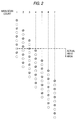
- Fig. 1 shows an arrangement of nozzle opening arrays of an ink-jet recording head according to a first embodiment of the present invention.
- Reference symbols K, C, M and Y denote nozzle opening arrays in a recording head 1 for independently ejecting black, cyan, magenta and yellow ink droplets, respectively.
- the nozzle opening arrays are arranged at the intervals equivalent to the print-pitch count for the nozzle openings 2, i.e., an interval of four print-pitches in this embodiment.
- the nozzle openings 2, the number of which is a relative prime number to the pitch count for the nozzle openings 2, five in this embodiment are aligned in the sub-scanning direction, i.e., in the paper feeding direction.
- the nozzle openings that eject cyan, magenta and yellow ink droplets, respectively, are arranged in rows that are shifted two print-pitches in sub-scanning direction away from the nozzle opening array K that ejects black ink droplets.
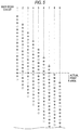
- a drive signal is transmitted to pressure generation means, such as a piezoelectric vibrator and a Joule heat generator that are independently provided in a pressure generation chamber communicating with the nozzle openings 2, during the first main scanning, as is shown in Fig. 2, black dots (hatched circles ⁇ in Fig. 2) are printed in a line that extends in the main scanning direction, and cyan, magenta and yellow dots (unhatched circles ⁇ in Fig. 2), the second group, are printed at a distance equivalent to two print-pitches from the line formed by the black dots.
- pressure generation means such as a piezoelectric vibrator and a Joule heat generator that are independently provided in a pressure generation chamber communicating with the nozzle openings 2
- black dots hatchched circles ⁇ in Fig. 2
- cyan, magenta and yellow dots unhatched circles ⁇ in Fig. 2
- the dots that were formed for the first scanning line are dry, so that ink smudging occasioned by the formation of succeeding dots not occur. Therefore, even when dots of colored inks in the second group are formed adjacent to black dots that were printed during the first scan, or when black dots are printed adjacent to dots of colored inks in the second group that were deposited during the first scan, even though the boundaries of the dots are overlapped, the inks of the black dots and of the other colored dots do not mix.
- the printing is thereafter continued with the recording medium being fed at constant five print-pitches, which is a number equal to that of the nozzle openings in each nozzle opening array. Since the paper feeding is performed at the constant pitch, a constant paper feeding distance error can be maintained, and printing without banding or blank areas can be provided.
- the dots printed with black ink, which constitutes the first group do not contact dots printed with other colored inks, which constitute the second group, until a period of time equivalent to at least one scan period has elapsed.
- the mixing of the ink in black dots with the inks of the other colored dots does not occur along the vertical boundary and the horizontal boundary (S in Figs. 3A to 3E denotes the number of scans).
- Fig. 4 shows the arrangement for the nozzle opening arrays of an ink-jet printing apparatus according to a second embodiment of the present invention.
- Reference symbols K, C, M and Y denote arrays of nozzle opening in a recording head 1 that independently eject black, cyan, magenta and yellow ink droplets.
- the nozzle opening arrays are arranged at intervals equivalent in number to the print-pitches used for arranging the nozzle openings 2, intervals of eight print-pitches in this embodiment.
- the nozzle openings 2, the number of which is a relative prime number, 8 in this embodiment, to the print-pitch count used for arranging the nozzle openings 2, i.e., five nozzle openings 2, are so arranged that they are shifted two print-pitches away from each other in the sub-scanning direction.
- the mixing of the colored inks, to include black, can be completely prevented, and color ink dots can be printed clearly.
- the printing is thereafter continued while the recording medium is fed by constant five print-pitches, a count that is equal to that of the nozzle openings. Since the paper feeding is performed at a constant print-pitch, a paper feeding distance error can be constant, and printing without banding or the production of blank areas can be provided.
- Figs. 7A and 7B show a third embodiment of the present invention that is appropriate for six-color printing using dark and light colored inks.
- Reference symbols K, C, M and Y denote arrays of nozzle openings in a recording head 1 that independently eject black, dark cyan, dark magenta and yellow ink droplets.
- Reference symbols c and m denote arrays of nozzle openings in the recording head 1 that independently eject light cyan and light magenta ink droplets.
- the nozzle opening arrays are arranged at intervals of four print-pitches, and nozzle openings 2, the number of which is a relative prime number to the pitch count for the nozzle opening arrangement, 63 in this embodiment, are arranged in the sub-scanning direction.
- the nozzle openings of the individual arrays of the first and the second groups are shifted two print-pitches in the sub-scanning direction.
- the dots hatchched ⁇ s in Fig. 7 are formed along individual lines using black, dark cyan, dark magenta and yellow ink droplets, and dots ( ⁇ s) for the light cyan and light magenta colors, which belong to the second group, are separately printed two print-pitches away from the dot line formed by the first group.
- the mixing of the inks used for dark cyan, dark magenta and yellow dots with light cyan and light magenta dots can be completely prevented, and light cyan and light magenta dots that contribute greatly to the enhancement of the color tones can be printed clearly.
- the light cyan and light magenta dots are printed on the same line, the image quality is very little affected by a change in color, when compared with when these inks are mixed with a black, dark cyan, dark magenta or yellow ink that has a high color density.
- the dots that were formed for the first scanning line are dry, and there is no smudging of the ink used to print the dots. Therefore, when dots printed with the light inks of the second group are placed adjacent to dots printed with the dark inks of the first group during the first scan, or when dots of dark ink are placed adjacent to dots printed with light ink during the first scan, even though the boundaries of dots are overlapped, the mixing of colors does not occur, and the light inks used for dots are not mixed with the dark colored inks.
- each nozzle opening array is formed by four print-pitches and the first group nozzle opening arrays are shifted from the second group nozzle opening arrays by two print-pitches. Therefore, in the same manner as previously described, the mixing of the inks used for the black, dark magenta and dark cyan dots with the inks used for the light cyan, light magenta and yellow dots can be prevented.
- the nozzle openings 2 through which the individually colored inks are ejected are arranged at the same print-pitches.
- a plurality of nozzle opening arrays K1, K2, K3 and K4 which have nozzle openings arranged at constant print-pitches for the ejection of black ink droplets, are shifted away from each other one print-pitch in the sub-scanning direction.
- all the nozzle opening arrays K1, K2, K3 and K4 are employed.
- nozzle opening arrays for ejecting dark colored ink i.e., nozzle opening arrays M, C and K4 in this embodiment
- nozzle opening arrays Y, m and c for ejecting light colored ink are employed to print text at a high dot density in order to ensure a high printing quality and a high printing speed.
- high quality printing of color data can be performed without light colored inks mixing with dark colored inks.
- the colored inks are sorted into a plurality of groups and nozzle opening arrays are shifted two or more pitches, ink smudging can be substantially prevented.
- the order of ejection of ink droplets of different groups can not be taken into consideration.
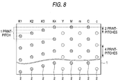
- rasters for dots respectively represented by hatched ⁇ , ⁇ , o ⁇ and ⁇ are scanned for printing. However, for one raster, dots represented by the hatched ⁇ are printed first, and for the other rasters, dots represented by ⁇ , o ⁇ or ⁇ are printed first.
- the ink smudging at the color boundary can be prevented as previously described, when different ink colored dots are to be formed and overlapped at the same position to express a specific color (for example, when a green dot is formed by overlapping a cyan C dot and a yellow Y dot), the compositions of these inks differ, so that in the actual printing the hue (the color tone) and the particle appearance are changed depending on which ink dots are formed first (for expressing green dots, there is a method for forming cyan dots first and then yellow dots, or a method for forming yellow dots first and then cyan dots).
- nozzle openings of different colored inks must be arranged in the same group to always form dots in the same order.
- Fig. 9A shows an example handling such a problem.
- Light cyan, dark cyan, black, light magenta, dark magenta and yellow nozzle opening arrays c, C, K, m, M and Y are located in the named order.
- the light cyan nozzle opening array c and the dark cyan nozzle opening array C are shifted away from each other three print-pitches
- the black nozzle opening array K and the light magenta nozzle opening array m are shifted away from each other three print-pitches
- the dark magenta nozzle opening array M and the yellow nozzle opening array Y are shifted away from each other three print-pitches.
- the cyan and yellow nozzle openings are located as the same group and the cyan dots are printed first. Furthermore, the magenta and light cyan nozzle openings are located as the same group and the light cyan dots are printed first. As a result, an increase in the particle appearance due to smudging is prevented, and black and yellow colors that tend to smudge are arranged as different groups to completely prevent them from being mixed.
- light magenta, dark cyan, black, light cyan, dark magenta and yellow nozzle opening arrays m, C, K, c, M and Y are arranged in the named order.
- the light magenta nozzle opening array m and the dark cyan nozzle opening array C are shifted away from each other three print-pitches
- the black nozzle opening array K and the light cyan nozzle opening array c are shifted away from each other three print-pitches
- the dark magenta nozzle opening array M and the yellow nozzle opening array Y are shifted each other by three print-pitches.
- the cyan, light cyan and yellow nozzle openings are located as the same group and the cyan and light cyan dots are printed first, so that the increase in the particle appearance due to smudging can be prevented, and black and yellow colors that tend to smudge are arranged as different groups to prevent them from being mixed.
- the recording head is so designed that a plurality of nozzle openings for each of the nozzle opening arrays are arranged at intervals of at least four or more print-pitches in the sub-scanning direction, that the nozzle opening arrays are divided into at least two groups, that the nozzle opening arrays belonging to each of the groups are positioned along the same line in the main scanning direction, and that the groups are shifted away from each other at least two print-pitches in the sub-scanning direction, and thus, color data can be printed by an interlace system.
- a recording medium can be fed at a constant distance, and ink dots whose colors may be changed due to color mixing can be printed at a time interval long enough to dry the ink, so that the mixing of colors, banding or the production blank areas can be prevented during printing, and high quality color printing can be provided.
Landscapes
- Character Spaces And Line Spaces In Printers (AREA)
- Ink Jet (AREA)
Applications Claiming Priority (3)
| Application Number | Priority Date | Filing Date | Title |
|---|---|---|---|
| JP9215991A JPH10278317A (ja) | 1997-02-04 | 1997-07-25 | インクジェット式記録装置 |
| JP21599197 | 1997-07-25 | ||
| JP215991/97 | 1997-07-25 |
Publications (2)
| Publication Number | Publication Date |
|---|---|
| EP0893265A2 true EP0893265A2 (de) | 1999-01-27 |
| EP0893265A3 EP0893265A3 (de) | 2000-05-10 |
Family
ID=16681601
Family Applications (1)
| Application Number | Title | Priority Date | Filing Date |
|---|---|---|---|
| EP98111607A Withdrawn EP0893265A3 (de) | 1997-07-25 | 1998-06-24 | Farbstrahldruckvorrichtung |
Country Status (1)
| Country | Link |
|---|---|
| EP (1) | EP0893265A3 (de) |
Cited By (2)
| Publication number | Priority date | Publication date | Assignee | Title |
|---|---|---|---|---|
| EP1331099A3 (de) * | 2002-01-24 | 2003-10-29 | Hewlett-Packard Company | Anordnung zur Verminderung des Effektes von durch Luftströmung verursachten Fehler in einer Vorrichtung zum auf Abruf Erzeugen von Tropfen |
| US7252357B2 (en) | 2002-05-22 | 2007-08-07 | Seiko Epson Corporation | Liquid ejecting apparatus |
Citations (1)
| Publication number | Priority date | Publication date | Assignee | Title |
|---|---|---|---|---|
| JPH04118250A (ja) | 1989-12-21 | 1992-04-20 | Hewlett Packard Co <Hp> | 多色インク・ジェット印字における印字工程およびこれに用いるインクジェットペン |
Family Cites Families (4)
| Publication number | Priority date | Publication date | Assignee | Title |
|---|---|---|---|---|
| US4593295A (en) * | 1982-06-08 | 1986-06-03 | Canon Kabushiki Kaisha | Ink jet image recording device with pitch-shifted recording elements |
| ATE221463T1 (de) * | 1993-02-05 | 2002-08-15 | Canon Kk | Farbstrahlaufzeichnungsgerät |
| JP3305182B2 (ja) * | 1995-02-02 | 2002-07-22 | セイコーエプソン株式会社 | シリアル記録装置 |
| JP3606403B2 (ja) * | 1995-04-27 | 2005-01-05 | セイコーエプソン株式会社 | 印刷装置および印刷方法 |
-
1998
- 1998-06-24 EP EP98111607A patent/EP0893265A3/de not_active Withdrawn
Patent Citations (1)
| Publication number | Priority date | Publication date | Assignee | Title |
|---|---|---|---|---|
| JPH04118250A (ja) | 1989-12-21 | 1992-04-20 | Hewlett Packard Co <Hp> | 多色インク・ジェット印字における印字工程およびこれに用いるインクジェットペン |
Cited By (2)
| Publication number | Priority date | Publication date | Assignee | Title |
|---|---|---|---|---|
| EP1331099A3 (de) * | 2002-01-24 | 2003-10-29 | Hewlett-Packard Company | Anordnung zur Verminderung des Effektes von durch Luftströmung verursachten Fehler in einer Vorrichtung zum auf Abruf Erzeugen von Tropfen |
| US7252357B2 (en) | 2002-05-22 | 2007-08-07 | Seiko Epson Corporation | Liquid ejecting apparatus |
Also Published As
| Publication number | Publication date |
|---|---|
| EP0893265A3 (de) | 2000-05-10 |
Similar Documents
| Publication | Publication Date | Title |
|---|---|---|
| US6325489B2 (en) | Ink-jet printing apparatus | |
| US4855752A (en) | Method of improving dot-on-dot graphics area-fill using an ink-jet device | |
| EP1106369B1 (de) | Kombination von Drucken in ein und zwei Richtungen unter Verwendung verschiedener Tintenarten | |
| US4750009A (en) | Color ink jet system printer capable of high definition printing | |
| EP0631257B1 (de) | Verfahren und Vorrichtung zur Tintenstrahlaufzeichnung | |
| EP0633139A1 (de) | Verkettetes Druckverfahren | |
| KR100612022B1 (ko) | 와이드 프린트헤드를 구비한 잉크젯 프린터의 인쇄방법 및장치 | |
| US6948796B2 (en) | Printing by switching sub-scan feeding between monochromatic and color areas | |
| US6719403B2 (en) | Ink-jet printing apparatus and ink-jet printing method | |
| EP0899681B1 (de) | Druckverfahren mit Tintenstrahdrucker mit verbesserter horizontalen Auflösung | |
| JP2002347230A5 (de) | ||
| JPH10244693A5 (de) | ||
| JPH09164706A (ja) | インクジェットヘッド | |
| KR20020036958A (ko) | 여러 가지 캐리지 속도를 이용하는 잉크젯프린터로프린트하는 방법 | |
| JP2002166535A (ja) | インクジェット記録装置、及びインクジェット記録方法 | |
| US6655783B2 (en) | Printing by switching sub-scanning feed between monochromatic areas and color areas | |
| US5959646A (en) | Method of printing with an ink jet printer using independent shingling on a raster by raster basis | |
| US5767875A (en) | Printing method and apparatus using serial print head | |
| US6682169B2 (en) | Printing by switching sub-scan feeding between monochromatic area and color area | |
| EP0893265A2 (de) | Farbstrahldruckvorrichtung | |
| JP2003048318A (ja) | 各色ノズルが副走査方向にずらして配されている印刷ヘッドによる印刷 | |
| US7073888B2 (en) | Ink jet recording device, and recording head | |
| JP2001138552A (ja) | インクジェットプリンタのインク色構成 | |
| EP0772150A1 (de) | Verschachtelter Farbtintenstrahldruck | |
| JP2003011337A (ja) | 2種類のインクを使用して記録対象領域を塗りつぶす印刷 |
Legal Events
| Date | Code | Title | Description |
|---|---|---|---|
| PUAI | Public reference made under article 153(3) epc to a published international application that has entered the european phase |
Free format text: ORIGINAL CODE: 0009012 |
|
| AK | Designated contracting states |
Kind code of ref document: A2 Designated state(s): DE FR GB IT |
|
| AX | Request for extension of the european patent |
Free format text: AL;LT;LV;MK;RO;SI |
|
| PUAL | Search report despatched |
Free format text: ORIGINAL CODE: 0009013 |
|
| AK | Designated contracting states |
Kind code of ref document: A3 Designated state(s): AT BE CH CY DE DK ES FI FR GB GR IE IT LI LU MC NL PT SE |
|
| AX | Request for extension of the european patent |
Free format text: AL;LT;LV;MK;RO;SI |
|
| 17P | Request for examination filed |
Effective date: 20000526 |
|
| AKX | Designation fees paid |
Free format text: DE FR GB IT |
|
| 17Q | First examination report despatched |
Effective date: 20010516 |
|
| STAA | Information on the status of an ep patent application or granted ep patent |
Free format text: STATUS: THE APPLICATION IS DEEMED TO BE WITHDRAWN |
|
| 18D | Application deemed to be withdrawn |
Effective date: 20020611 |