EP0893312A2 - Fahrerseitiges Gassack-Rückhaltesystem für Fahrzeuge - Google Patents
Fahrerseitiges Gassack-Rückhaltesystem für Fahrzeuge Download PDFInfo
- Publication number
- EP0893312A2 EP0893312A2 EP98118638A EP98118638A EP0893312A2 EP 0893312 A2 EP0893312 A2 EP 0893312A2 EP 98118638 A EP98118638 A EP 98118638A EP 98118638 A EP98118638 A EP 98118638A EP 0893312 A2 EP0893312 A2 EP 0893312A2
- Authority
- EP
- European Patent Office
- Prior art keywords
- steering wheel
- gas
- restraint system
- gap
- sealing gap
- Prior art date
- Legal status (The legal status is an assumption and is not a legal conclusion. Google has not performed a legal analysis and makes no representation as to the accuracy of the status listed.)
- Granted
Links
Images



Classifications
-
- B—PERFORMING OPERATIONS; TRANSPORTING
- B60—VEHICLES IN GENERAL
- B60R—VEHICLES, VEHICLE FITTINGS, OR VEHICLE PARTS, NOT OTHERWISE PROVIDED FOR
- B60R21/00—Arrangements or fittings on vehicles for protecting or preventing injuries to occupants or pedestrians in case of accidents or other traffic risks
- B60R21/02—Occupant safety arrangements or fittings, e.g. crash pads
- B60R21/16—Inflatable occupant restraints or confinements designed to inflate upon impact or impending impact, e.g. air bags
- B60R21/20—Arrangements for storing inflatable members in their non-use or deflated condition; Arrangement or mounting of air bag modules or components
- B60R21/203—Arrangements for storing inflatable members in their non-use or deflated condition; Arrangement or mounting of air bag modules or components in steering wheels or steering columns
- B60R21/2032—Arrangements for storing inflatable members in their non-use or deflated condition; Arrangement or mounting of air bag modules or components in steering wheels or steering columns the inflator or inflatable member not being rotatable with the steering wheel; Arrangements using the steering column or steering wheel rim for storing, supplying or evacuating the inflation gas or for storing the inflatable member
-
- B—PERFORMING OPERATIONS; TRANSPORTING
- B60—VEHICLES IN GENERAL
- B60R—VEHICLES, VEHICLE FITTINGS, OR VEHICLE PARTS, NOT OTHERWISE PROVIDED FOR
- B60R21/00—Arrangements or fittings on vehicles for protecting or preventing injuries to occupants or pedestrians in case of accidents or other traffic risks
- B60R21/02—Occupant safety arrangements or fittings, e.g. crash pads
- B60R21/16—Inflatable occupant restraints or confinements designed to inflate upon impact or impending impact, e.g. air bags
- B60R21/26—Inflatable occupant restraints or confinements designed to inflate upon impact or impending impact, e.g. air bags characterised by the inflation fluid source or means to control inflation fluid flow
- B60R21/30—Inflatable occupant restraints or confinements designed to inflate upon impact or impending impact, e.g. air bags characterised by the inflation fluid source or means to control inflation fluid flow with means to draw ambient air into the flow line and mix such air with the inflation fluid
Definitions
- the invention relates to a driver-side gas bag restraint system for vehicles with one located outside the steering wheel Gas source for filling the gas bag arranged on the steering wheel hub and one between the gas source and the inflow opening of the gas bag arranged gas routing.
- a pyrotechnic gas generator integrated in the steering wheel hub.
- the gas generator is triggered by an electrical pulse that a deceleration sensor delivers.
- the gas source includes several pressurized gas containers, which are fixed in the Vehicle are installed.
- a pipe leads from each compressed gas tank to a rotary coupling consisting of a fixed distributor plate and one that is in sliding contact with it and rotatable with the steering wheel hub Distribution disc is formed.
- Such a rotary coupling is complex in the manufacture and affected by the frictional resistance the smoothness of the steering wheel between the distributor disks.
- the invention specified in claim 1 is a Driver-side gas bag restraint system created for vehicles at which the gas flow between the steering wheel hub and the outside of the Steering wheel arranged gas source free from the smoothness of the Steering wheel is affecting friction and with little Effort can be produced in series.
- a wall of the gas duct which is fixed with respect to the vehicle body sealed without contact between these gap boundary surfaces.
- the sealing gap is only by the shape and arrangement of certain areas the steering wheel hub and on the steering column, for which there is only one requires little effort in material and construction.
- the invention is based on the knowledge that the gas flow from the gas source to into the gas bag at an existing one on the way of the gas routing Sealing gap can not escape, but even at the sealing gap jet pump effect supporting the filling of the gas bag occurs, through which ambient air is sucked into the gas flow.
- the invention is based on the knowledge that the sealing gap when immersed the vehicle occupant in the inflated airbag in advantageous Way a controlled flow of the filling gas at least supported.
- the relief openings required in conventional designs in the wall of the gas bag can at least partially omitted. This is also advantageous in that injuries of the occupant due to any particles emerging from the gas bag or hot gases can be avoided.
- a particularly space-saving and easy in a vehicle integrable embodiment is in the claims 2 and 3 specified.
- an extended compressed gas container 12 of generally cylindrical shape on the outside and parallel arranged to the axis of the steering column.
- the one from the tubular steering column 10 surrounded steering shaft 14 carries at its end facing the driver a steering wheel 16, the hub with a central passage for the Has threaded end of the steering shaft 14 and by means of a Screw nut is attached to it (Fig. 4).
- folded gas bag 18 is arranged on the hub of the steering wheel 16 and is opened by a tearable cover 20 on the driver Side covered. Between the compressed gas tank 12 and the Inside the gas bag 18 there is a gas guide, which is below is described in more detail.
- the compressed gas container 12 is provided with a closure 12A to activate the restraint system, for example by means of a small pyrotechnic charge can be destroyed.
- a pipeline 22 is connected to the compressed gas container 12, which extends parallel to the steering column 10 along its outer surface and into an annular plenum surrounding the steering shaft 14 24 flows into.
- This distribution chamber 24 is of a general pot-shaped wall limited, the peripheral part 24A cylindrical and whose bottom 24B is flat; this pot-shaped wall is in one piece with the pipe 22 connected and open to the side of the steering wheel.
- the hub 16A of the steering wheel 16 faces the distribution chamber 24 four through openings 26 arranged on a circle.
- the Through openings 26 are through spokes 28 arranged in the manner of spokes delimited, the cross section of which has a streamlined profile, as shown in Fig. 6.
- the side surfaces of the webs 28 converge each towards the distribution chamber 24 and form a common one Edge on the steering wheel hub 16A is a peripheral part 24A of the Apron 16B formed around distribution chamber 24.
- An annular sealing gap 30 is formed on the peripheral part 24A.
- the axial length of the sealing gap 30 corresponds approximately to the height of the distribution chamber 24.
- the openings are 26 of the steering wheel hub 16A immediately the open side of the distribution chamber 24 opposite. Furthermore, the openings 26 are located directly on the Injection opening of the folded gas bag 18 opposite.
- This Rotary coupling 32 consists of a spiral "clockwork spring" in a cylindrical housing attached to the bottom 24B and one to the Steering wheel hub 16A non-rotatably coupled, the steering shaft 14 sleeve-shaped surrounding guide part, from which a connection of the rotary coupling led out is.
- this is the steering wheel hub 16A facing end of the peripheral part 24A of the cup-shaped wall formed as a flexible sealing lip 40.
- This flexible sealing lip 40 assumes the position shown in FIG. 7 in the idle state, in which releases the sealing gap 30.
- the sealing lip 40 acts as a valve to The gas filling flows out via the relatively wide sealing gap 30 prevent.
- the sealing lip 40 gives the Sealing gap 30 is free again and thus opens one depending on the internal pressure Relief route.
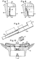
- Fig. 9 shows an embodiment of the pipeline between the Distribution chamber 24 and the gas source (not shown) for one in the Steering wheel adjustable in depth.
- the pipeline consists of two telescopes telescoping pipe sections 22A and 22B. By this configuration becomes the length of the sealing gap during adjustment the steering wheel is not changed. If the steering wheel is also in the According to a further development of this embodiment, the height should be adjustable provided at least section 22A of the pipeline partially flexible training.
- Fig. 10 one is finished with folded airbag 18A and with a cover 20A equipped steering wheel assembly 60 shown for Assembly at the end of a steering shaft is ready.
- the gas bag 18A is tubular trained so that it has a central free space when folded for placing the nut on the end of the steering shaft.
- the cover 20A is provided with a corresponding recess, in which inserted a plug 42 after assembly of the steering wheel assembly can be.
- Figures 11 to 14 show different embodiments of the Sealing gap. 11 extends the Sealing gap 30B radially with respect to the axis of the steering shaft between two flat gap boundary surfaces on the mutually facing sides of the Steering wheel hub and the wall surrounding the distribution chamber 24.
- the embodiment according to FIG. 12 differs from that according to FIG. 11 due to the labyrinthine design of the sealing gap 30C.
- the sealing gap 30D is different 4 step-shaped, which increases the length of the sealing gap and the flow resistance is increased.
- this is the steering wheel hub 16A facing end of the peripheral portion 24A of the plenum 24 bounding wall by a flexible sealing lip 50 formed, which is deflected by the gas flow when filling the gas bag and seals the sealing gap 30E (dashed position). At the sealing lip 50 moves in the opposite direction of flow the opposite direction and releases the sealing gap 30E.
Landscapes
- Engineering & Computer Science (AREA)
- Mechanical Engineering (AREA)
- Physics & Mathematics (AREA)
- Fluid Mechanics (AREA)
- Air Bags (AREA)
Abstract
Description
Claims (6)
- Fahrerseitiges Gassack-Rückhaltesystem für Fahrzeuge, mit einem außerhalb des Lenkrades (16) angeordneten Druckgasspeicher (12) zum Befüllen des an der Lenkradnabe (16A) angeordneten Gassacks (18) und einer zwischen dem Druckgasspeicher (12) und der Einströmöffnung des Gassacks (18) angeordneten Gasführung, dadurch gekennzeichnet, daß die Gasführung an ihrem Übergang zu dem Lenkrad (16) durch einen ringförmigen Dichtspalt (30) zwischen einer an der Lenkradnabe (16A) gebildeten ersten Spaltbegrenzungsfläche und einer gegenüberliegenden zweiten Spaltbegrenzungsfläche an einer bezüglich des Fahrzeugaufbaus feststehenden Wandung (24A) der Gasführung ohne Berührung zwischen diesen Spaltbegrenzungsflächen abgedichtet ist, daß der Dichtspalt (30) durch seine Dimensionierung und Anordnung relativ zur Strömungsrichtung der Gase das Einsaugen von Außenluft durch den Dichtspalt (30) unter der Wirkung der Gasströmung im Inneren der Gasführung aufgrund des Strahlpumpen-Effektes ermöglicht und daß die Gasführung eine die Lenkwelle (14) ringförmig umgebende, topfförmige Verteilerkammer (24) aufweist, an der die zweite Spaltbegrenzungsfläche gebildet ist, wobei der Dichtspalt (30C) eine Labyrinth-Dichtung bildet.
- Gassack-Rückhaltesystem nach Anspruch 1, dadurch gekennzeichnet, daß der Druckgasspeicher (12) einen allgemein zylinderförmig gestreckten Druckbehälter aufweist, der parallel zur Lenksäule (10) angeordnet und durch eine parallel zur Lenksäule (10) und außerhalb von dieser angeordnete Rohrleitung (22) mit dem Innenraum der Verteilerkammer (24) verbunden ist.
- Gassack-Rückhaltesystem nach Anspruch 2, für ein in der Tiefe verstellbares Lenkrad, dadurch gekennzeichnet, daß die Rohrleitung aus teleskopartig ineinander verschiebbaren Abschnitten (22A, 22B) zusammengesetzt ist.
- Gassack-Rückhaltesystem nach einem der Ansprüche 1 bis 3, dadurch gekennzeichnet, daß der Dichtspalt (30) zwischen dem zylindrischen Umfangsteil (24A) der die Verteilerkammer (24) begrenzenden Wandung und der Innenseite einer die Verteilerkammer (24) umgebenden, an die Lenkradnabe (16A) angeformten Schürze (16B) gebildet ist.
- Gassack-Rückhaltesystem nach einem der vorherstehenden Ansprüche, dadurch gekennzeichnet, daß mehrere Gasdurchtrittsöffnungen (26) in der Nabe (16A) des Lenkrades zwischen speichenförmig angeordneten Stegen (28) ausgebildet sind, die jeweils zur Verteilerkammer (24) hin konvergierende Seitenflächen aufweisen.
- Lenkrad für ein Gassack-Rückhaltesystem nach einem der vorstehenden Ansprüche, dadurch gekennzeichnet, daß es mit dem schlauchringförmig ausgebildeten, zusammengefalteten und mit einer Abdeckung (20A) versehenen Gassack (18A) eine vormontierte Baugruppe (60) bildet.
Applications Claiming Priority (4)
| Application Number | Priority Date | Filing Date | Title |
|---|---|---|---|
| DE43079695 | 1993-03-12 | ||
| DE43079695F | 1993-03-12 | ||
| DE4307969A DE4307969A1 (de) | 1993-03-12 | 1993-03-12 | Fahrerseitiges Gassack-Rückhaltesystem für Fahrzeuge |
| EP94102975A EP0614787B1 (de) | 1993-03-12 | 1994-02-28 | Fahrerseitiges Gassack-Rückhaltesystem für Fahrzeuge |
Related Parent Applications (1)
| Application Number | Title | Priority Date | Filing Date |
|---|---|---|---|
| EP94102975A Division EP0614787B1 (de) | 1993-03-12 | 1994-02-28 | Fahrerseitiges Gassack-Rückhaltesystem für Fahrzeuge |
Publications (3)
| Publication Number | Publication Date |
|---|---|
| EP0893312A2 true EP0893312A2 (de) | 1999-01-27 |
| EP0893312A3 EP0893312A3 (de) | 1999-03-03 |
| EP0893312B1 EP0893312B1 (de) | 2001-09-26 |
Family
ID=6482677
Family Applications (2)
| Application Number | Title | Priority Date | Filing Date |
|---|---|---|---|
| EP98118638A Expired - Lifetime EP0893312B1 (de) | 1993-03-12 | 1994-02-28 | Fahrerseitiges Gassack-Rückhaltesystem für Fahrzeuge |
| EP94102975A Expired - Lifetime EP0614787B1 (de) | 1993-03-12 | 1994-02-28 | Fahrerseitiges Gassack-Rückhaltesystem für Fahrzeuge |
Family Applications After (1)
| Application Number | Title | Priority Date | Filing Date |
|---|---|---|---|
| EP94102975A Expired - Lifetime EP0614787B1 (de) | 1993-03-12 | 1994-02-28 | Fahrerseitiges Gassack-Rückhaltesystem für Fahrzeuge |
Country Status (5)
| Country | Link |
|---|---|
| US (1) | US5398963A (de) |
| EP (2) | EP0893312B1 (de) |
| JP (1) | JP2813541B2 (de) |
| DE (3) | DE4307969A1 (de) |
| ES (2) | ES2068798T3 (de) |
Families Citing this family (23)
| Publication number | Priority date | Publication date | Assignee | Title |
|---|---|---|---|---|
| DE19509165A1 (de) * | 1995-03-14 | 1996-09-19 | Mst Automotive Gmbh | Gassack-Aufprallschutz-System |
| US5553888A (en) * | 1995-06-26 | 1996-09-10 | Alliedsignal Inc. | Snap-on, removable steering wheel with integral airbag housing |
| US5692769A (en) * | 1995-09-01 | 1997-12-02 | Breed Automotive Technology, Inc. | Modular steering wheel and air bag combination |
| DE19544394C2 (de) * | 1995-11-15 | 2001-03-22 | Claus Busch | Airbag-System |
| US7744122B2 (en) * | 1995-12-12 | 2010-06-29 | Automotive Technologies International, Inc. | Driver side aspirated airbags |
| US5820160A (en) * | 1996-03-01 | 1998-10-13 | Autoliv Asp, Inc. | Airbag inflator with venturi effect cooling and gas supplement |
| US5685559A (en) * | 1996-04-25 | 1997-11-11 | Trw Inc. | Steering wheel with air bag module |
| US5829780A (en) * | 1996-10-07 | 1998-11-03 | Chrysler Corporation | Air bag and inflator assembly |
| DE19648136A1 (de) * | 1996-11-21 | 1998-05-28 | Opel Adam Ag | Gehäuse mit einer Kammer zur Aufnahme eines zusammengefalteten und aufblasbaren Luftsackes |
| JPH10236256A (ja) * | 1997-02-26 | 1998-09-08 | Tokai Rika Co Ltd | エアバッグ装置 |
| DE29821621U1 (de) | 1998-12-03 | 1999-01-28 | TRW Automotive Safety Systems GmbH, 63743 Aschaffenburg | Aufprall-Schutzvorrichtung für Kraftfahrzeuge |
| US6227571B1 (en) * | 1999-11-03 | 2001-05-08 | Trw Vehicle Safety Systems Inc. | Telescoping vehicle steering column apparatus for helping to protect a vehicle driver |
| SE518451C2 (sv) * | 2000-07-03 | 2002-10-08 | Saab Automobile | Rattarrangemang för ett motorfordon |
| US6382661B1 (en) * | 2000-11-20 | 2002-05-07 | Trw Vehicle Safety Systems Inc. | Vehicle steering wheel having inflatable devices |
| DE10145664B4 (de) * | 2001-09-15 | 2011-04-14 | GM Global Technology Operations, Inc., Detroit | Airbag-Modul |
| JP2003182500A (ja) * | 2001-12-25 | 2003-07-03 | Takata Corp | 乗員保護装置 |
| US6517105B1 (en) * | 2002-04-12 | 2003-02-11 | Breed Automotive Technology, Inc. | Steering wheel assembly featuring the elimination of a contact coil |
| DE202004003464U1 (de) | 2004-03-05 | 2005-07-14 | Trw Automotive Safety Systems Gmbh | Lenkrad für ein Kraftfahrzeug mit einem Gassackmodul |
| FR2899540B1 (fr) * | 2006-04-11 | 2009-01-02 | Peugeot Citroen Automobiles Sa | Ensemble de direction a "air bag" pour vehicule automobile |
| DE202006007751U1 (de) * | 2006-05-12 | 2006-07-27 | Trw Automotive Safety Systems Gmbh | Lenkvorrichtung für ein Kraftfahrzeug |
| AU2011261399A1 (en) * | 2010-06-02 | 2012-12-20 | Automotive Technologies International, Inc. | Airbag system |
| US9039038B2 (en) | 2010-06-02 | 2015-05-26 | Automotive Technologies International, Inc. | Steering wheel mounted aspirated airbag system |
| DE202021106650U1 (de) | 2021-12-07 | 2023-03-08 | ZF Automotive Safety Germany GmbH | Lenkvorrichtung für ein Kraftfahrzeug |
Family Cites Families (21)
| Publication number | Priority date | Publication date | Assignee | Title |
|---|---|---|---|---|
| US3580603A (en) * | 1968-07-19 | 1971-05-25 | Eaton Yale & Towne | Inflatable safety apparatus |
| US4126325A (en) * | 1970-06-20 | 1978-11-21 | Klippan Gmbh Hamburg | Inflatable air bag for motor vehicles for attenuating the impact effect of the passenger in case of accident |
| US3680884A (en) * | 1970-10-21 | 1972-08-01 | Allied Chem | Vehicle safety assembly |
| GB1324401A (en) * | 1970-12-29 | 1973-07-25 | Kidde & Co Walter | Vehicle safety device |
| JPS5119893B2 (de) * | 1971-12-08 | 1976-06-21 | ||
| BE794296A (fr) * | 1972-01-19 | 1973-07-19 | Des Soc Nat | Nouveau dispositif de securite a coussin gonflable, notamment pour vehicules uatomobiles |
| JPS5146932B2 (de) * | 1972-02-29 | 1976-12-11 | ||
| US3787075A (en) * | 1972-10-30 | 1974-01-22 | Gen Motors Corp | Steering wheel and column interface seal |
| JPS5319159Y2 (de) * | 1973-07-25 | 1978-05-22 | ||
| IT1017358B (it) * | 1973-07-26 | 1977-07-20 | Eaton Corp | Complesso per trattenere l occu pante di un veicolo |
| US3863948A (en) * | 1973-10-05 | 1975-02-04 | Olin Corp | Rotary connection for a safety bag inflation system |
| JPS5391239A (en) * | 1977-01-19 | 1978-08-10 | Arakawa Shatai Kogyo | Air bag serving as safety device for vehicle |
| JPS5519627A (en) * | 1978-07-24 | 1980-02-12 | Honda Motor Co Ltd | Air bag device |
| DE3630685C2 (de) * | 1986-07-22 | 1994-03-10 | Trw Repa Gmbh | Gaskissen-Aufprallschutzvorrichtung für einen Kraftfahrzeuginsassen |
| US4877264A (en) * | 1988-12-27 | 1989-10-31 | Talley Automotive Products, Inc. | Aspirating/venting air bag module assembly |
| JPH03149103A (ja) * | 1989-11-07 | 1991-06-25 | Toshin Seiki Kk | 工作機械の軸受装置 |
| FR2658776B1 (fr) * | 1990-02-28 | 1993-06-18 | Ecia Equip Composants Ind Auto | Colonne de direction reglable. |
| JPH0426340A (ja) * | 1990-05-18 | 1992-01-29 | Nagano Nippon Densan Kk | スピンドルモータ |
| JPH04203425A (ja) * | 1990-11-30 | 1992-07-24 | Yanmar Diesel Engine Co Ltd | ガスタービンのタービン側軸受潤滑装置 |
| DE4226101A1 (de) * | 1992-08-07 | 1994-02-10 | Pars Passive Rueckhaltesysteme | Lenkung für Kraftfahrzeuge |
| JPH0692221A (ja) * | 1992-09-14 | 1994-04-05 | Mazda Motor Corp | アンチスキッドブレーキ装置の作動点検装置 |
-
1993
- 1993-03-12 DE DE4307969A patent/DE4307969A1/de not_active Ceased
-
1994
- 1994-02-28 EP EP98118638A patent/EP0893312B1/de not_active Expired - Lifetime
- 1994-02-28 ES ES94102975T patent/ES2068798T3/es not_active Expired - Lifetime
- 1994-02-28 EP EP94102975A patent/EP0614787B1/de not_active Expired - Lifetime
- 1994-02-28 DE DE59409883T patent/DE59409883D1/de not_active Expired - Fee Related
- 1994-02-28 ES ES98118638T patent/ES2165121T3/es not_active Expired - Lifetime
- 1994-02-28 DE DE59408998T patent/DE59408998D1/de not_active Expired - Fee Related
- 1994-03-03 US US08/206,592 patent/US5398963A/en not_active Expired - Fee Related
- 1994-03-11 JP JP6041349A patent/JP2813541B2/ja not_active Expired - Lifetime
Also Published As
| Publication number | Publication date |
|---|---|
| ES2068798T3 (es) | 2000-04-01 |
| ES2068798T1 (es) | 1995-05-01 |
| DE59409883D1 (de) | 2001-10-31 |
| JPH07132792A (ja) | 1995-05-23 |
| JP2813541B2 (ja) | 1998-10-22 |
| ES2165121T3 (es) | 2002-03-01 |
| EP0614787B1 (de) | 1999-12-15 |
| EP0893312A3 (de) | 1999-03-03 |
| EP0893312B1 (de) | 2001-09-26 |
| DE59408998D1 (de) | 2000-01-20 |
| US5398963A (en) | 1995-03-21 |
| EP0614787A1 (de) | 1994-09-14 |
| DE4307969A1 (de) | 1994-09-15 |
Similar Documents
| Publication | Publication Date | Title |
|---|---|---|
| EP0614787B1 (de) | Fahrerseitiges Gassack-Rückhaltesystem für Fahrzeuge | |
| EP0760318B1 (de) | Scheibenwascheinrichtung für Kraftfahrzeuge, insbesondere Fahrzeugscheinwerfer | |
| US4045008A (en) | Gas spring | |
| EP1572488B1 (de) | Kraftstoffbehälter mit funktionsbauteil-träger sowie träger für funktionsbauteile eines kfz-kraftstoffbehälters | |
| DE69505740T2 (de) | Einfüllstutzen für einen Kraftstoffbehälter | |
| EP1842798B1 (de) | Dosierventil und Vorrichtung zur Abgabe einer vorzugsweise kosmetischen Flüssigkeit | |
| EP0932526B1 (de) | Verfahren zur sicherung eines fahrzeuginsassen und airbagmodul zur durchführung des verfahrens | |
| DE2146258A1 (de) | Insassensicherheitseinrichtung für Fahrzeuge | |
| EP0584782A1 (de) | Gassack-Rückhaltesystem für Fahrzeuge | |
| DE1961391U (de) | Druckmittelservoantrieb. | |
| DE2253657A1 (de) | Vorrichtung zum spannen von sicherheitsgurten in fahrzeugen | |
| EP4130510A1 (de) | Fluiddämpfer mit einem schaltkolben, verfahren zur herstellung des fluiddämpfers, antriebsanordnung mit dem fluiddämpfer | |
| DE2115302A1 (de) | Fahrzeug zur Personenbeförderung, insbesondere Personenkraftwagen, mit einem Stoßdampfungssystem | |
| DE102015016193A1 (de) | Pyrotechnischer Aktuator für ein Fahrzeugsicherheitssystem, Aktuatorbaugruppe, Fahrzeugsicherheitssystem mit einem solchen Aktuator sowie Betätigungsverfahren | |
| WO2005058654A1 (de) | Airbageinrichtung für ein kraftfahrzeug | |
| EP2176096B1 (de) | Airbagmodul für ein kraftfahrzeug | |
| DE4226101A1 (de) | Lenkung für Kraftfahrzeuge | |
| DE69300487T2 (de) | Pneumatischer kraftverstärker. | |
| DE19821838A1 (de) | Gassackanordnung mit gesteuertem Aufblasverhalten | |
| DE2143165A1 (de) | Lenkrad fuer ein kraftfahrzeug o. dgl | |
| EP4077066B1 (de) | Gasgenerator insbesondere für ein fahrzeugsicherheitssystem | |
| DE4028990A1 (de) | Gasgenerator zum aufblasen einer gaskissen-rueckhalteeinrichtung von fahrzeugen | |
| EP1154909B1 (de) | Ventil und ein mit einem ventil versehener kraftstoffbehälter eines kraftfahrzeuges | |
| DE69407447T2 (de) | Deckel für Druckbehälter | |
| DE19956931A1 (de) | Ventil und ein mit einem Ventil versehener Kraftstoffbehälter eines Kraftfahrzeuges |
Legal Events
| Date | Code | Title | Description |
|---|---|---|---|
| PUAI | Public reference made under article 153(3) epc to a published international application that has entered the european phase |
Free format text: ORIGINAL CODE: 0009012 |
|
| PUAL | Search report despatched |
Free format text: ORIGINAL CODE: 0009013 |
|
| AC | Divisional application: reference to earlier application |
Ref document number: 614787 Country of ref document: EP |
|
| AK | Designated contracting states |
Kind code of ref document: A2 Designated state(s): DE ES FR GB IT SE |
|
| RTI1 | Title (correction) | ||
| AK | Designated contracting states |
Kind code of ref document: A3 Designated state(s): DE ES FR GB IT SE |
|
| 17P | Request for examination filed |
Effective date: 19990715 |
|
| 17Q | First examination report despatched |
Effective date: 20000531 |
|
| GRAG | Despatch of communication of intention to grant |
Free format text: ORIGINAL CODE: EPIDOS AGRA |
|
| GRAG | Despatch of communication of intention to grant |
Free format text: ORIGINAL CODE: EPIDOS AGRA |
|
| GRAH | Despatch of communication of intention to grant a patent |
Free format text: ORIGINAL CODE: EPIDOS IGRA |
|
| GRAH | Despatch of communication of intention to grant a patent |
Free format text: ORIGINAL CODE: EPIDOS IGRA |
|
| GRAA | (expected) grant |
Free format text: ORIGINAL CODE: 0009210 |
|
| AC | Divisional application: reference to earlier application |
Ref document number: 614787 Country of ref document: EP |
|
| AK | Designated contracting states |
Kind code of ref document: B1 Designated state(s): DE ES FR GB IT SE |
|
| REF | Corresponds to: |
Ref document number: 59409883 Country of ref document: DE Date of ref document: 20011031 |
|
| PG25 | Lapsed in a contracting state [announced via postgrant information from national office to epo] |
Ref country code: SE Free format text: LAPSE BECAUSE OF FAILURE TO SUBMIT A TRANSLATION OF THE DESCRIPTION OR TO PAY THE FEE WITHIN THE PRESCRIBED TIME-LIMIT Effective date: 20011226 |
|
| REG | Reference to a national code |
Ref country code: GB Ref legal event code: IF02 |
|
| GBT | Gb: translation of ep patent filed (gb section 77(6)(a)/1977) |
Effective date: 20011201 |
|
| PGFP | Annual fee paid to national office [announced via postgrant information from national office to epo] |
Ref country code: GB Payment date: 20020108 Year of fee payment: 9 |
|
| ET | Fr: translation filed | ||
| PGFP | Annual fee paid to national office [announced via postgrant information from national office to epo] |
Ref country code: FR Payment date: 20020131 Year of fee payment: 9 |
|
| PGFP | Annual fee paid to national office [announced via postgrant information from national office to epo] |
Ref country code: ES Payment date: 20020213 Year of fee payment: 9 |
|
| REG | Reference to a national code |
Ref country code: ES Ref legal event code: FG2A Ref document number: 2165121 Country of ref document: ES Kind code of ref document: T3 |
|
| PLBE | No opposition filed within time limit |
Free format text: ORIGINAL CODE: 0009261 |
|
| STAA | Information on the status of an ep patent application or granted ep patent |
Free format text: STATUS: NO OPPOSITION FILED WITHIN TIME LIMIT |
|
| 26N | No opposition filed | ||
| PG25 | Lapsed in a contracting state [announced via postgrant information from national office to epo] |
Ref country code: GB Free format text: LAPSE BECAUSE OF NON-PAYMENT OF DUE FEES Effective date: 20030228 |
|
| PGFP | Annual fee paid to national office [announced via postgrant information from national office to epo] |
Ref country code: DE Payment date: 20030228 Year of fee payment: 10 |
|
| PG25 | Lapsed in a contracting state [announced via postgrant information from national office to epo] |
Ref country code: ES Free format text: LAPSE BECAUSE OF NON-PAYMENT OF DUE FEES Effective date: 20030301 |
|
| GBPC | Gb: european patent ceased through non-payment of renewal fee | ||
| PG25 | Lapsed in a contracting state [announced via postgrant information from national office to epo] |
Ref country code: FR Free format text: LAPSE BECAUSE OF NON-PAYMENT OF DUE FEES Effective date: 20031031 |
|
| REG | Reference to a national code |
Ref country code: FR Ref legal event code: ST |
|
| REG | Reference to a national code |
Ref country code: ES Ref legal event code: FD2A Effective date: 20030301 |
|
| PG25 | Lapsed in a contracting state [announced via postgrant information from national office to epo] |
Ref country code: DE Free format text: LAPSE BECAUSE OF NON-PAYMENT OF DUE FEES Effective date: 20040901 |
|
| PG25 | Lapsed in a contracting state [announced via postgrant information from national office to epo] |
Ref country code: IT Free format text: LAPSE BECAUSE OF NON-PAYMENT OF DUE FEES;WARNING: LAPSES OF ITALIAN PATENTS WITH EFFECTIVE DATE BEFORE 2007 MAY HAVE OCCURRED AT ANY TIME BEFORE 2007. THE CORRECT EFFECTIVE DATE MAY BE DIFFERENT FROM THE ONE RECORDED. Effective date: 20050228 |