EP0893364A1 - Dispositif pour le conditionnement séparé de deux composants - Google Patents
Dispositif pour le conditionnement séparé de deux composants Download PDFInfo
- Publication number
- EP0893364A1 EP0893364A1 EP98401717A EP98401717A EP0893364A1 EP 0893364 A1 EP0893364 A1 EP 0893364A1 EP 98401717 A EP98401717 A EP 98401717A EP 98401717 A EP98401717 A EP 98401717A EP 0893364 A1 EP0893364 A1 EP 0893364A1
- Authority
- EP
- European Patent Office
- Prior art keywords
- shutter
- containers
- passage
- fact
- container
- Prior art date
- Legal status (The legal status is an assumption and is not a legal conclusion. Google has not performed a legal analysis and makes no representation as to the accuracy of the status listed.)
- Withdrawn
Links
Images




Classifications
-
- B—PERFORMING OPERATIONS; TRANSPORTING
- B65—CONVEYING; PACKING; STORING; HANDLING THIN OR FILAMENTARY MATERIAL
- B65D—CONTAINERS FOR STORAGE OR TRANSPORT OF ARTICLES OR MATERIALS, e.g. BAGS, BARRELS, BOTTLES, BOXES, CANS, CARTONS, CRATES, DRUMS, JARS, TANKS, HOPPERS, FORWARDING CONTAINERS; ACCESSORIES, CLOSURES, OR FITTINGS THEREFOR; PACKAGING ELEMENTS; PACKAGES
- B65D81/00—Containers, packaging elements, or packages, for contents presenting particular transport or storage problems, or adapted to be used for non-packaging purposes after removal of contents
- B65D81/32—Containers, packaging elements, or packages, for contents presenting particular transport or storage problems, or adapted to be used for non-packaging purposes after removal of contents for packaging two or more different materials which must be maintained separate prior to use in admixture
- B65D81/3205—Separate rigid or semi-rigid containers joined to each other at their external surfaces
- B65D81/3211—Separate rigid or semi-rigid containers joined to each other at their external surfaces coaxially and provided with means facilitating admixture
-
- Y—GENERAL TAGGING OF NEW TECHNOLOGICAL DEVELOPMENTS; GENERAL TAGGING OF CROSS-SECTIONAL TECHNOLOGIES SPANNING OVER SEVERAL SECTIONS OF THE IPC; TECHNICAL SUBJECTS COVERED BY FORMER USPC CROSS-REFERENCE ART COLLECTIONS [XRACs] AND DIGESTS
- Y10—TECHNICAL SUBJECTS COVERED BY FORMER USPC
- Y10S—TECHNICAL SUBJECTS COVERED BY FORMER USPC CROSS-REFERENCE ART COLLECTIONS [XRACs] AND DIGESTS
- Y10S215/00—Bottles and jars
- Y10S215/08—Mixing
Definitions
- the present invention relates to a device for separate packaging of two components to be mixed during first use and for the distribution of the mixture obtained.
- the invention relates more particularly to a device comprising two superimposed containers able to communicate with each other by a passage and being able to turn relative to each other around an axis of rotation without moving axially, a shutter single disposed in said passage to close it during storage separated from the components, one of the containers further comprising guide means for guiding the movement of the shutter in said passage and the other container comprising means to transform the relative rotation of the two containers in axial displacement of the shutter in said guide means, causing the opening of the passage and mixing components.
- This type of device makes it possible to mix the components without volume reduction so without creating overpressure likely to spray mixture on opening.
- German patent DE 44 36 863 C1 a device with two containers of relatively complex structure, comprising two shutters which deviate from each other during the relative rotation of containers.
- the present invention relates to a new device allowing to remedy all or part of the aforementioned drawbacks.
- the shutter has retaining means able to limit its axial movement in said guide means at the end of the relative rotation of said containers.
- the shutter is prevented from obstructing the flow of the mixture when it is distributed and its cost is substantially independent of the size of the containers since it does not have to extend over the entire height of one either of these.
- the aforementioned blocking problem linked to the shutter does not twist.
- the means guides are shaped to guide the shutter in translation.
- these guide means have a non-symmetrical throttle of revolution formed in the passage.
- the shutter then comprises a barrel shaped to cooperate with these guide means and the retaining means are formed by at least one relief projecting at one end of it was.
- the shutter comprises a skirt having shaped recesses to cooperate with the guide means and the retaining means are constituted by the material of the skirt at the end of these recesses.
- the guide means have shaped grooves to guide the sliding of the shutter tabs and the retaining means are constituted by a crown connecting said legs.
- the means drive comprise at least one thread which can be, in a particular embodiment, formed on a ring subject to one containers or alternatively, formed directly by molding on one containers.
- the means drive have a helical ramp shaped to gradually press the shutter when the two containers are rotated relative to each other.
- the shutter comprises a compartment intended to contain a third component and the device further comprises in the passage through which the two containers communicate a perforated transverse wall shaped to close this compartment when the shutter is initially in place in the passage.
- This third component is for example a perfume which mixes to the other two components when using the device.
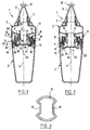
- a device 1 conforms to a first embodiment of the invention.
- This device 1 comprises a lower container 2 and a upper container 3 which can rotate relative to each other around an axis of rotation which coincides with the longitudinal axis X of the device.
- the lower container 2 has at its upper part a neck 4 provided with an annular bead 5 on which a ring engages 6.
- the upper container 3 has at its upper part a neck threaded 7 and it is partially engaged at its lower part 8 in collar 4.
- a dispensing nozzle 9 having a breakable end 10 is screwed onto the neck 7.
- the lower part 8 is connected to the rest of the container upper 3 by forming a constriction 11 whose cross section transverse is non-symmetrical in revolution around the X axis.
- the throttle 11 has two diametrically opposite projections 12.
- the ring 6 has an outer skirt 13 and two skirts concentric 14 and 15, which are connected by a wall 18 in forming an annular groove 16 open upwards, in which the lower part 8 of the upper container 3 is engaged.
- the inner skirt 14 has on its face radially inner two threads 17 each extending over a little less than a U-turn around the X axis and symmetrical to each other by relation to this axis.
- the threads 17 constitute drive means in the sense of the present invention, as will be explained later.
- the wall 18, which constitutes the bottom of the aforementioned groove 16, is extended downwards by two annular sealing lips 19 and 20 providing an annular groove 21 therebetween.
- the intermediate skirt 15 is connected to the outer skirt 13 in forming an annular groove 22 open downwards and in which Col 4 is engaged.
- Reliefs 23 surmounted by recesses are made on the wall through which the intermediate skirt 15 is connected to the skirt 13 to snap onto the annular bead 5. The case where appropriate, the reliefs 23 can also ensure the blocking in rotation of the ring 6 relative to the lower container 2.
- the intermediate skirt 15 further comprises, at its end upper and on its radially inner surface, a bead annular 24 which retains by snapping teeth 25 forming protrusion on the radially outer surface of the lower part 8 of the upper container 3.
- the upper container 3 comes to bear on the upper edge of the outer skirt 13 so that it can rotate relative to without moving axially along the X axis.
- a shutter 26 makes it possible to separate the components contained respectively in the lower container 2 and in the container upper 3 until the first use of the device 1.
- It can be two liquids or a liquid and a powder.
- One of the components consists for example of an oxidant and the other by a dye, which mixed with the first forms a dye capillary.
- Container upper can for example be made of polyvinyl chloride, the lower polyethylene container and the shutter in polypropylene.
- Shutter 26 is shown in isolation in FIGS. 4 to 7.
- the shutter 26 comprises a hollow barrel 27 provided, at mid-height approximately and on its radially outer surface, of two pins 28 diametrically opposed, shaped to engage in threads 17.
- the barrel 27 has at its upper part and at its part lower of the openings 30 and 31 respectively intended to cooperate with the advances 12 and to allow the flow of the contained component in the upper container 3 to the lower container 2 when the first use of the device.
- the barrel 27 is further provided with longitudinal ribs 32 interior, located along the longitudinal edges of openings 30 and 31.
- These ribs 32 are provided at their upper end with teeth 33 constituting retaining means within the meaning of this invention, capable of coming to bear on the upper edges of the 12 throttles 11 advanced to prevent the shutter 26 from fall into the lower container 2, as will be specified in the after.
- the barrel 27 is connected at its lower end to a plug 34 provided at its periphery with an annular sealing lip 35 which household with the rest of the cap an annular groove 36.
- the assembly of the device 1 is carried out as follows.
- the shutter 26 is screwed into the inner skirt 14 until that the lip 35 is inserted into the groove 21.
- the upper container 3 is positioned above the ring 6, the projections 12 being oriented so as to engage between the ribs 32.
- the upper container 3 is then lowered until it clicks into place on the bead 24 of the intermediate skirt 15.
- the teeth 33 cross the projections by elastic deformation 12.
- the upper container 3 is filled with one of the components and then the tip 9 is screwed thereon.
- the lower container 2 is filled with the other component, then the assembly constituted by the upper container 3 and the ring 6 is snapped onto the neck 4.
- the seal between the ring 6 and the container lower 2 is provided by the intermediate skirt 15 which comes apply tightly by its radially outer surface on the radially inner surface of the neck 4 and that the seal between the ring 6 and the upper container 3 is provided by the skirt interior 14 which is applied by its radially surface outer on the radially inner surface of the part lower 8.
- the user turns the container upper 3 relative to the lower container 2 and the ring 6.
- the shutter 26 rotates with the upper container 3 due to cooperation between the projections 12 and the ribs 32.
- the shutter 26 thus rotated is moved towards the bottom by threads 17, ribs 32 sliding on the projections 12 engaged in openwork 30.
- the component contained in the upper container 3 can win the lower container 2 through the inside of the barrel 27 and through the openings 31.
- advances 12 constitute means of guide located at the passage through which the containers lower 2 and upper 3 communicate.
- the shutter has a relatively small axial size compared to the device described in the previous French patent application 2,691,950 cited above.
- FIGS. 8 to 11 show a device 40 according to a second embodiment of the invention.
- This device 40 includes certain constituent elements identical to those of the previous embodiment, which does not will not be described again and assigned the same references.
- the device 40 differs from the previous one essentially by the shape of the shutter, referenced 41, and by the shape of the skirt interior, referenced 43.
- the ring snapped onto the lower container 2 is here referenced 42.
- the shutter 41 is moved upward when the container upper 3 is rotated relative to the container lower 2 to cause the components to mix.
- the inner skirt 43 has two threads 44 on its face radially outer and two annular sealing lips 45 and 46 concentric at its upper end.
- the threads 44 are symmetrical to each other with respect to the X axis and constitute training means within the meaning of the present invention.
- the shutter 41 has at its upper part a plug 47 provided with an annular sealing lip 48, intended to engage in the groove formed between the lips 45 and 46, during storage separate from components.
- the plug 47 is extended at its periphery downwards by a skirt 49 provided in two diametrically opposite locations on its radially inner surface of lugs 50 adapted to engage each in a thread 44.
- the skirt 49 has two diametrically opposite recesses 51 in which the advances 12 of the upper container 3 are engaged.
- the shutter 41 is locked in rotation relative to the upper container 3 while being able to move axially by compared to this one.
- the recesses 51 do not extend to the end bottom of skirt 49, so that regions 52 of skirt 49 located below these recesses 51 limit the axial displacement from the shutter upwards and constitute retaining means at the meaning of the present invention.
- the device 40 is assembled by screwing the shutter 41 on the inner skirt 43 until contact is obtained tight between the sealing lips 45, 46 and 48, then the container upper 3 is snapped into the ring 42.
- the nozzle 9 is put in place and the assembly is attached to the lower container 2, which has been completed beforehand.
- the user turns the upper container 3 relative to the lower container 2, which causes the shutter 41 to rotate in the threads 44 and its ascent, until it takes the position shown on the Figures 10 and 11, the regions 52 abutting the projections 12.
- the component contained in the upper container then drains through the recesses 51 in the lower container 2.
- FIGS. 12 to 17 show a device 60 according to a third embodiment of the invention.
- This device 60 comprises a lower container 61 in the form of a bottle with a neck 62.
- the container upper 63 has a closed threaded neck 64 at its upper part by a dispensing nozzle 65 provided with a breakable part 66.
- the upper container 63 has a lower part 67 partially engaged in the neck 62 of the lower container 61.
- the neck 62 is provided, in the vicinity of its upper end, of an annular bead 68 radially projecting towards the outside, on which a ring 69 is snapped on.
- the latter comprises an outer skirt 70 and a skirt interior 71 which are connected by a wall 72 substantially frustoconical, provided with reliefs 73 surmounted by recesses, these reliefs being intended to snap onto the annular bead 68.
- the inner skirt 71 is engaged in the collar 62 and is supported by an annular rim 76 on the edge thereof.
- the inner skirt 71 is further provided at its end upper and on its radially inner surface of a bead ring 74 onto which teeth 75 made on the radially outer surface of the lower part 67 of the upper container 63.
- the upper container 63 comes to bear on the outer skirt 70 so that it can rotate relative to the lower container without moving axially.
- Notches 97 are formed under the annular bead 74, to cooperate with teeth 75 and block the container in rotation upper 63 and the ring 69.
- the inner skirt 71 is closed at its lower part by a transverse wall 78, carrying on its upper face a lip sealing ring 77 which is applied sealingly on the radially inner surface of the lower part 67 of the upper container 63.
- a recess 96 cylindrical of revolution around the axis X, is formed in the center of the wall 78 and openings 79 are made between this recess 96 and the lip 77.
- the neck 62 has at its base staves 98 arranged in so as to form two diametrically opposite grooves 99, as shown in figure 17.
- a shutter 80 allows the components to be separated contained respectively in the lower and upper containers before the first use of the device 60.
- FIG. 16 shows this shutter 80 in isolation.
- This comprises a central barrel 81, closed at its end lower 82, and provided at its upper end with a lip sealing ring 83 intended to be applied sealingly, when the shutter 80 is in its initial position, on the periphery of the step 96 to form a sealed compartment 84 able to contain a third component, for example a perfume, stored without contact with the other two components.
- a third component for example a perfume
- the barrel 81 is extended radially outwards, at the base of the annular sealing lip 83, through a transverse wall 85 provided at its periphery and on its upper face with an annular lip seal 86, concentric to the lip 83.
- the shutter 80 has at its upper part a crown 87 larger in diameter than the transverse wall 85 and which is connects to the latter by two connecting lugs 88 diametrically opposite.
- the legs 88 each provide a groove 89 with the lip sealing ring 86.
- the inner skirt 71 has an annular sealing lip 90 which is applied to the radially inner surface of the lip 86 for sealing between the ring 69 and the shutter 80.
- the lower edge of the inner skirt 71 forms a ramp helical 92 extending a little less than half a turn.
- the ramp 92 is located outside gorges 89.
- the ramp 92 engages in one of the grooves 89 and presses on the bottom of this groove, which drives shutter 80 downwards.
- the latter is prevented from turn by the legs 88 which are locked in rotation in the gorges 99 and slide therein.
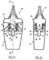
- FIGS. 14 and 15 show the device 60 after the rotation of the two containers 61 and 63.
- the component contained in the upper container 63 can flow into the lower container through the openings 79.
- the component contained in the shutter 81 can leave the latter when the device 60 is returned.
- FIGS. 18 to 20 show a device 100 in accordance with a fourth embodiment of the invention.
- This device 100 includes a lower container 101 with a neck 102 and an upper container 103 in the form of a capsule snapped onto collar 102.
- the upper container 103 comprises a mounting skirt 104 provided with reliefs 105 surmounted by recesses, these reliefs 105 being intended to snap onto an annular bead 106 produced on the outside surface of the neck 102.
- the skirt 104 is supported by its lower edge on a shoulder of the lower container 101 formed at the base of the neck 102, so that the upper container 103 can rotate relative to the lower container without moving axially.
- the upper container 103 also includes a chimney central 107 located inside the mounting skirt 104 and a lip sealing ring 108 which extends downwards in space annular which exists between the mounting skirt 104 and the chimney 107.
- the lip 108 is applied tightly to the surface radially inside of the neck 102.
- the central chimney 107 has two external threads 110 symmetrical to each other with respect to the X axis.
- the neck 102 has at its base two pairs of spans 111 protruding inwards, similar to the ranges 98 described with reference to Figure 17.
- the components are separated before the first use of the device 100 by a shutter 112 which has been shown in isolation in Figure 20.
- This shutter 112 comprises a plug constituted by a disc 113 provided on its upper face with two annular lips sealing 114 and 115 concentric and also includes a crown 116 connected to the disc 113 by two legs 117 diametrically opposite.
- Two diametrically opposite lugs 120 are formed on the face radially inner of the crown 116 to engage with the threads 110.
- the legs 117 are housed in the grooves formed between the carried 111 and can slide axially therein.
- the lower end 123 of the chimney 107 engages between the lips 114 and 115 when the shutter 112 is in its initial position before the first use of the device, such as shown in figure 18.
- the user turns the upper container 103 relative to the lower container 101.
- the shutter 112 being prevented from turning relative to the lower container 101, the threads 110 drive down the pins 120, which causes the opening of the lower end of the chimney 107 as shown in FIG. 19 and the descent of the component in the upper container 103 in the container lower 101.
- the mixture of the components takes place at constant volume without creating an overpressure liable to spray mixture at the opening of the device.
Landscapes
- Engineering & Computer Science (AREA)
- Mechanical Engineering (AREA)
- Closures For Containers (AREA)
- Package Specialized In Special Use (AREA)
- Sliding Valves (AREA)
- Details Of Rigid Or Semi-Rigid Containers (AREA)
Abstract
Description
- les figures 1 et 2 représentent un dispositif conforme à un premier exemple de réalisation de l'invention, respectivement avant et après mélange des composants,
- la figure 3 est une section transversale du contenant supérieur, selon le trait de coupe III-III de la figure 1,
- la figure 4 est une coupe axiale, schématique et partielle, de l'obturateur représenté sur les figures 1 et 2,
- la figure 5 est une vue de côté selon la flèche V de la figure 4,
- la figure 6 est une vue de dessus selon la flèche VI de la figure 4,
- la figure 7 est une coupe partielle selon le trait de coupe VII-VII de la figure 6,
- la figure 8 est une coupe longitudinale, schématique, d'un dispositif conforme à un deuxième exemple de réalisation de l'invention, avant mélange des composants,
- la figure 9 est une vue selon le trait de coupe IX-IX de la figure 8,
- la figure 10 est une vue analogue à la figure 8, représentant le dispositif après mélange des composants,
- la figure 11 est une vue selon le trait de coupe XI-XI de la figure 10,
- la figure 12 est une coupe longitudinale, schématique, d'un dispositif conforme à un troisième exemple de réalisation de l'invention,
- la figure 13 est une vue selon le trait de coupe XIII-XIII de la figure 12,
- la figure 14 est une vue analogue à la figure 12, représentant le dispositif après mélange des composants,
- la figure 15 est une vue selon le trait de coupe XV-XV de la figure 14,
- la figure 16 représente isolément, en perspective, l'obturateur équipant le dispositif représenté sur les figures 12 à 15,
- la figure 17 représente isolément, en vue de dessus, le contenant inférieur,
- les figures 18 et 19 sont deux coupes longitudinales représentant un dispositif conforme à un quatrième exemple de réalisation de l'invention, respectivement avant et après mélange des composants, et
- la figure 20 représente isolément, en perspective, l'obturateur équipant le dispositif représenté sur les figures 18 et 19.
Claims (12)
- Dispositif pour le conditionnement séparé de deux composants à mélanger lors de la première utilisation et pour la distribution du mélange obtenu, du type comportant deux contenants superposés aptes à communiquer entre eux par un passage et pouvant tourner l'un par rapport à l'autre autour d'un axe de rotation sans se déplacer axialement, un obturateur unique disposé dans ledit passage pour l'obturer pendant le stockage séparé des composants, l'un des contenants comportant en outre des moyens de guidage pour guider le déplacement de l'obturateur dans ledit passage et l'autre contenant comportant des moyens d'entraínement pour transformer la rotation relative des deux contenants en un déplacement axial de l'obturateur dans lesdits moyens de guidage, provoquant l'ouverture du passage, caractérisé par le fait que l'obturateur comporte en outre des moyens de retenue (33;52;87;116) aptes à limiter son déplacement dans lesdits moyens de guidage (12;99) au terme de la rotation relative des contenants (2,3;61,63;101,103).
- Dispositif selon la revendication 1, caractérisé par le fait que lesdits moyens de guidage sont conformés pour guider l'obturateur en translation.
- Dispositif selon la revendication 2, caractérisé par le fait que lesdits moyens de guidage comportent un étranglement non symétrique de révolution (11) formé dans ledit passage.
- Dispositif selon la revendication 3, caractérisé par le fait que ledit obturateur (26) comporte un fût (27) conformé pour coopérer avec lesdits moyens de guidage (12) et par le fait que lesdits moyens de retenue sont constitués par au moins un relief (33) formant saillie à une extrémité de ce fût.
- Dispositif selon la revendication 3, caractérisé par le fait que ledit obturateur comporte une jupe (49) présentant des évidements conformés pour coopérer avec lesdits moyens de guidage (12), et par le fait que lesdits moyens de retenue sont constitués par la matière de la jupe à l'extrémité de ces évidements (51).
- Dispositif selon la revendication 2, caractérisé par le fait que lesdits moyens de guidage comportent des gorges (99) conformées pour guider en coulissement des pattes (88;117) de l'obturateur et par le fait que lesdits moyens de retenue sont constitués par une couronne (87;116) reliant lesdites pattes.
- Dispositif selon l'une quelconque des revendications précédentes, caractérisé par le fait que lesdits moyens d'entraínement comportent au moins un filetage (17;44;110).
- Dispositif selon la revendication 7, caractérisé par le fait que ce filetage est formé sur une bague (6;42;69) assujettie à l'un des contenants.
- Dispositif selon la revendication 7, caractérisé par le fait que le filetage (110) est formé directement par moulage sur l'un des contenants.
- Dispositif selon l'une quelconque des revendications 1 à 6, caractérisé par le fait que lesdits moyens d'entraínement comportent une rampe hélicoïdale (92) conformée pour appuyer progressivement sur l'obturateur (80) lorsque les deux contenants sont entraínés en rotation l'un par rapport à l'autre.
- Dispositif selon l'une quelconque des revendications 1 à 10, caractérisé par le fait que ledit obturateur comporte un compartiment (81) destiné à contenir un troisième composant et par le fait que le dispositif comporte en outre dans ledit passage une paroi transversale ajourée (78) conformée pour fermer ce compartiment lorsque l'obturateur est initialement en place dans ledit passage.
- Dispositif selon la revendication 11, caractérisé par le fait que ledit troisième composant est un parfum.
Applications Claiming Priority (2)
| Application Number | Priority Date | Filing Date | Title |
|---|---|---|---|
| FR9708663A FR2765859B1 (fr) | 1997-07-08 | 1997-07-08 | Dispositif pour le conditionnement de deux composants |
| FR9708663 | 1997-07-08 |
Publications (1)
| Publication Number | Publication Date |
|---|---|
| EP0893364A1 true EP0893364A1 (fr) | 1999-01-27 |
Family
ID=9509005
Family Applications (1)
| Application Number | Title | Priority Date | Filing Date |
|---|---|---|---|
| EP98401717A Withdrawn EP0893364A1 (fr) | 1997-07-08 | 1998-07-07 | Dispositif pour le conditionnement séparé de deux composants |
Country Status (6)
| Country | Link |
|---|---|
| US (1) | US5992693A (fr) |
| EP (1) | EP0893364A1 (fr) |
| JP (1) | JPH1170976A (fr) |
| AR (1) | AR013181A1 (fr) |
| CA (1) | CA2241296A1 (fr) |
| FR (1) | FR2765859B1 (fr) |
Families Citing this family (37)
| Publication number | Priority date | Publication date | Assignee | Title |
|---|---|---|---|---|
| AU7026998A (en) * | 1997-05-15 | 1998-12-08 | R + D Injector Ag | Dual-component container system |
| FR2789372B1 (fr) * | 1999-02-10 | 2001-04-13 | Oreal | Dispositif pour le stockage de trois composants, leur melange et la distribution du melange ainsi obtenu |
| FR2789979B1 (fr) * | 1999-02-22 | 2001-05-04 | Oreal | Conditionnement pour effectuer le melange d'un produit a plusieurs composantes |
| FR2810639B1 (fr) * | 2000-06-21 | 2002-09-06 | Oreal | Ensemble pour le melange extemporane de deux produits |
| US6290100B1 (en) | 2000-06-30 | 2001-09-18 | Canberra Corporation | Concentrate cartridge for a diluting and dispensing container |
| FR2811636B1 (fr) | 2000-07-17 | 2002-09-20 | Oreal | Dispositif pour le conditionnement separe de deux ou trois composants a melanger extemporanement |
| KR100706535B1 (ko) * | 2001-06-21 | 2007-06-07 | 정재석 | 소형 향수 배합장치 |
| USD465697S1 (en) | 2001-07-12 | 2002-11-19 | Playtex Products, Inc. | Agitator |
| AU2002354938A1 (en) | 2001-07-18 | 2003-03-03 | Playtex Products, Inc. | Bottle with mixing system |
| IL160007A0 (en) | 2001-08-06 | 2004-06-20 | Uc Technologies & Engineering | Multi-compartment container assembly system |
| JP4400705B2 (ja) * | 2002-03-29 | 2010-01-20 | 株式会社タニ | 内容物の混合構造を有する包装容器 |
| US7482116B2 (en) | 2002-06-07 | 2009-01-27 | Dna Genotek Inc. | Compositions and methods for obtaining nucleic acids from sputum |
| JP2007532416A (ja) * | 2004-04-08 | 2007-11-15 | アイディーディー−イール マニュファクチャリング カンパニー リミテッド | 液状の配合物を調合するための容器 |
| WO2006027782A2 (fr) * | 2004-09-09 | 2006-03-16 | Liran Katz | Contenant |
| US20060049127A1 (en) * | 2004-09-09 | 2006-03-09 | Liran Katz | Container |
| US20070166269A1 (en) * | 2005-12-01 | 2007-07-19 | L'oreal | Cosmetic composition containing a statistical polymer with a linear chain of ethylenic nature |
| CA113861S (en) | 2005-12-09 | 2007-08-22 | Dna Genotek Inc | Vial |
| CN101370425B (zh) | 2005-12-09 | 2011-08-24 | Dna吉诺特克股份有限公司 | 用于可释放地储存物质的容器系统 |
| US20090308889A1 (en) * | 2008-06-11 | 2009-12-17 | Frank Lindsay | Container system |
| US8157131B2 (en) * | 2008-10-15 | 2012-04-17 | Sim Jae K | Spray bottle with refill cartridge |
| US8302816B2 (en) * | 2008-10-15 | 2012-11-06 | Sim Jae K | Spray bottle with refill cartridge |
| US8261943B2 (en) * | 2008-10-15 | 2012-09-11 | Sim Jae K | Spray bottle with refill cartridge |
| US8430137B2 (en) | 2010-08-24 | 2013-04-30 | Jae K. Sim | Refill cap cartridge |
| CN103402882B (zh) * | 2011-02-01 | 2016-01-06 | 花岗岩州产品发展有限责任公司 | 用于容器的分配帽 |
| US10065775B2 (en) | 2011-02-01 | 2018-09-04 | Granite State Product Development LLC | Dispensing cap for a container |
| EP3150702B1 (fr) | 2011-06-19 | 2021-05-19 | DNA Genotek, Inc. | Dispositifs, solutions et procédés de collecte d'échantillons |
| US9145221B2 (en) * | 2012-03-20 | 2015-09-29 | La Prairie, Inc. | Convertible two compartment container |
| KR101478978B1 (ko) * | 2013-01-15 | 2015-01-07 | (주)연우 | 이종 내용물 혼합용기 |
| KR101598043B1 (ko) * | 2015-01-14 | 2016-02-26 | (주)연우 | 거품분출 튜브용기 |
| US11242236B2 (en) | 2015-03-19 | 2022-02-08 | Phillip LaBarbera | Perfect pour drink mixer |
| DE102015118053A1 (de) * | 2015-10-22 | 2017-04-27 | Rpc Bramlage Gmbh | Verschlusseinrichtung für einen Behälter |
| ES2928337T3 (es) * | 2017-12-01 | 2022-11-17 | Oreal | Dispositivo para envasar dos productos por separado |
| BR112020024130A2 (pt) * | 2018-06-01 | 2021-02-17 | In Spirit Group, Inc. | sistema de garrafa de bebida e método para fabricar uma garrafa de bebida multicompartimentada |
| US12207724B2 (en) * | 2018-11-07 | 2025-01-28 | L'oreal | Device for packaging and dispensing a product having an improved sealing between two containers |
| GB201819975D0 (en) * | 2018-12-07 | 2019-01-23 | Windridge Katherine | A container |
| DE102019203858A1 (de) * | 2019-03-21 | 2020-09-24 | Henkel Ag & Co. Kgaa | Verpackungssystem für zumindest eine Produktzubereitungskomponente sowie zugehöriges Verfahren zur Handhabung der Produktzubereitungskomponente |
| KR102135610B1 (ko) * | 2019-04-15 | 2020-07-22 | 주식회사 삼화 | 이종 내용물 혼합용기 |
Citations (2)
| Publication number | Priority date | Publication date | Assignee | Title |
|---|---|---|---|---|
| FR2707601A3 (fr) * | 1991-01-03 | 1995-01-20 | Wassilieff Victor | Récipient de fluide comportant une fermeture reliée par glissement avec un capuchon fileté d'un côté et la bague filetée du récipient de l'autre côté. |
| DE4436863C1 (de) * | 1994-10-14 | 1996-01-25 | Henkel Kgaa | Behälterverbindungsvorrichtung |
Family Cites Families (4)
| Publication number | Priority date | Publication date | Assignee | Title |
|---|---|---|---|---|
| US4734565A (en) * | 1983-10-12 | 1988-03-29 | Drexler Technology Corporation | Read-only optical card and system |
| FR2691950B1 (fr) * | 1992-06-09 | 1996-05-15 | Scopic | Conditionnement melangeur pour deux composants a stocker separement, et a melanger extemporanement a la premiere utilisation. |
| DE4428096A1 (de) * | 1994-08-09 | 1996-02-15 | Wella Ag | Zweikammerbehälter |
| FR2751941B1 (fr) * | 1996-08-02 | 1998-09-11 | Oreal | Dispositif pour le conditionnement separe de deux composants, leur melange et la distribution du melange ainsi obtenu |
-
1997
- 1997-07-08 FR FR9708663A patent/FR2765859B1/fr not_active Expired - Fee Related
-
1998
- 1998-06-25 US US09/104,405 patent/US5992693A/en not_active Expired - Fee Related
- 1998-07-06 AR ARP980103274A patent/AR013181A1/es unknown
- 1998-07-07 CA CA002241296A patent/CA2241296A1/fr not_active Abandoned
- 1998-07-07 EP EP98401717A patent/EP0893364A1/fr not_active Withdrawn
- 1998-07-08 JP JP10192822A patent/JPH1170976A/ja not_active Ceased
Patent Citations (2)
| Publication number | Priority date | Publication date | Assignee | Title |
|---|---|---|---|---|
| FR2707601A3 (fr) * | 1991-01-03 | 1995-01-20 | Wassilieff Victor | Récipient de fluide comportant une fermeture reliée par glissement avec un capuchon fileté d'un côté et la bague filetée du récipient de l'autre côté. |
| DE4436863C1 (de) * | 1994-10-14 | 1996-01-25 | Henkel Kgaa | Behälterverbindungsvorrichtung |
Also Published As
| Publication number | Publication date |
|---|---|
| FR2765859B1 (fr) | 1999-09-24 |
| FR2765859A1 (fr) | 1999-01-15 |
| US5992693A (en) | 1999-11-30 |
| CA2241296A1 (fr) | 1999-01-08 |
| JPH1170976A (ja) | 1999-03-16 |
| AR013181A1 (es) | 2000-12-13 |
Similar Documents
| Publication | Publication Date | Title |
|---|---|---|
| FR2765859A1 (fr) | Dispositif pour le conditionnement de deux composants | |
| CA2141967C (fr) | Distributeur a plusieurs compartiments pour le stockage et le melange du contenu | |
| EP0893365B1 (fr) | Dispositif pour le conditionnement séparé de deux composants et procédé de fabrication | |
| EP1028069B1 (fr) | Dispositif pour le stockage de trois composants, leur mélange et la distribution du mélange ainsi obtenu | |
| EP1044893B1 (fr) | Dispositif pour le mélange extemporané d'au moins deux produits dont un est notamment une poudre | |
| EP0694483B1 (fr) | Récipient permettant le stockage d'au moins deux produits, le mélange de ces produits et la distribution du mélange ainsi obtenu | |
| CA2209329C (fr) | Dispositif pour le stockage separe d'au moins deux produits, leur melange et la distribution du melange ainsi obtenu et procede de fabrication | |
| EP0822148A1 (fr) | Dispositif pour le conditionnement séparé de deux composants, leur mélange et la distribution du mélange ainsi obtenu | |
| EP0812775B1 (fr) | Récipient de mélange et de distribution de deux composants | |
| EP0822147A1 (fr) | Dispositif pour le stockage séparé de deux composants, leur mélange et la distribution du mélange | |
| FR2908116A1 (fr) | Distributeur de produit fluide | |
| EP1145981A1 (fr) | Capsule de distribution et récipient équipé d'une telle capsule | |
| EP1033323B1 (fr) | Conditionnement pour effectuer le mélange d'un produit à plusieurs composants | |
| FR2806271A1 (fr) | Dispositif pour le melange extemporane d'au moins deux produits | |
| EP0238371A1 (fr) | Réservoir contenant un liquide pâteux auquel un additif est ajouté à la première utilisation | |
| FR2765860A1 (fr) | Capsule de bouchage a bec verseur auto-eclipsable | |
| FR2767794A1 (fr) | Ensemble de deux elements montes libres en rotation l'un par rapport a l'autre notamment pour un melangeur dans le domaine de la coloration capillaire | |
| EP0905049B1 (fr) | Conditionnement pour un produit à trois composants | |
| FR2689102A3 (fr) | Bouchon permettant de boire destiné à une gourde. | |
| FR2687640A1 (fr) | Dispositif pour conserver separes l'un de l'autre au moins deux produits et pour effectuer leur melange ulterieurement, notamment au moment de l'utilisation. | |
| FR2946028A1 (fr) | Element d'embouchure pour un recipient, destine a etre visse avec un element d'embouchure complementaire du recipient. | |
| EP1425988B1 (fr) | Dispositif de conditionnement d'un produit fluide | |
| FR2768407A1 (fr) | Dispositif de bouchage et flacon equipe d'un tel dispositif | |
| FR2876557A1 (fr) | Stylo distributeur d'un produit cosmetique fluide | |
| FR2811636A1 (fr) | Dispositif pour le conditionnement separe de deux ou trois composants a melanger extemporanement |
Legal Events
| Date | Code | Title | Description |
|---|---|---|---|
| PUAI | Public reference made under article 153(3) epc to a published international application that has entered the european phase |
Free format text: ORIGINAL CODE: 0009012 |
|
| AK | Designated contracting states |
Kind code of ref document: A1 Designated state(s): DE ES FR GB IT |
|
| AX | Request for extension of the european patent |
Free format text: AL;LT;LV;MK;RO;SI |
|
| 17P | Request for examination filed |
Effective date: 19990608 |
|
| AKX | Designation fees paid |
Free format text: DE ES FR GB IT |
|
| GRAG | Despatch of communication of intention to grant |
Free format text: ORIGINAL CODE: EPIDOS AGRA |
|
| 17Q | First examination report despatched |
Effective date: 20020527 |
|
| GRAG | Despatch of communication of intention to grant |
Free format text: ORIGINAL CODE: EPIDOS AGRA |
|
| GRAH | Despatch of communication of intention to grant a patent |
Free format text: ORIGINAL CODE: EPIDOS IGRA |
|
| STAA | Information on the status of an ep patent application or granted ep patent |
Free format text: STATUS: THE APPLICATION IS DEEMED TO BE WITHDRAWN |
|
| 18D | Application deemed to be withdrawn |
Effective date: 20030111 |