EP0893405A2 - Vorrichtung zur Erzeugung von Ozon - Google Patents
Vorrichtung zur Erzeugung von Ozon Download PDFInfo
- Publication number
- EP0893405A2 EP0893405A2 EP98250366A EP98250366A EP0893405A2 EP 0893405 A2 EP0893405 A2 EP 0893405A2 EP 98250366 A EP98250366 A EP 98250366A EP 98250366 A EP98250366 A EP 98250366A EP 0893405 A2 EP0893405 A2 EP 0893405A2
- Authority
- EP
- European Patent Office
- Prior art keywords
- ozone generating
- elastic body
- generating apparatus
- electrodes
- ozone
- Prior art date
- Legal status (The legal status is an assumption and is not a legal conclusion. Google has not performed a legal analysis and makes no representation as to the accuracy of the status listed.)
- Withdrawn
Links
Images


Classifications
-
- C—CHEMISTRY; METALLURGY
- C01—INORGANIC CHEMISTRY
- C01B—NON-METALLIC ELEMENTS; COMPOUNDS THEREOF; METALLOIDS OR COMPOUNDS THEREOF NOT COVERED BY SUBCLASS C01C
- C01B13/00—Oxygen; Ozone; Oxides or hydroxides in general
- C01B13/10—Preparation of ozone
- C01B13/11—Preparation of ozone by electric discharge
-
- C—CHEMISTRY; METALLURGY
- C01—INORGANIC CHEMISTRY
- C01B—NON-METALLIC ELEMENTS; COMPOUNDS THEREOF; METALLOIDS OR COMPOUNDS THEREOF NOT COVERED BY SUBCLASS C01C
- C01B2201/00—Preparation of ozone by electrical discharge
- C01B2201/10—Dischargers used for production of ozone
- C01B2201/12—Plate-type dischargers
-
- C—CHEMISTRY; METALLURGY
- C01—INORGANIC CHEMISTRY
- C01B—NON-METALLIC ELEMENTS; COMPOUNDS THEREOF; METALLOIDS OR COMPOUNDS THEREOF NOT COVERED BY SUBCLASS C01C
- C01B2201/00—Preparation of ozone by electrical discharge
- C01B2201/20—Electrodes used for obtaining electrical discharge
- C01B2201/22—Constructional details of the electrodes
-
- C—CHEMISTRY; METALLURGY
- C01—INORGANIC CHEMISTRY
- C01B—NON-METALLIC ELEMENTS; COMPOUNDS THEREOF; METALLOIDS OR COMPOUNDS THEREOF NOT COVERED BY SUBCLASS C01C
- C01B2201/00—Preparation of ozone by electrical discharge
- C01B2201/30—Dielectrics used in the electrical dischargers
- C01B2201/32—Constructional details of the dielectrics
-
- C—CHEMISTRY; METALLURGY
- C01—INORGANIC CHEMISTRY
- C01B—NON-METALLIC ELEMENTS; COMPOUNDS THEREOF; METALLOIDS OR COMPOUNDS THEREOF NOT COVERED BY SUBCLASS C01C
- C01B2201/00—Preparation of ozone by electrical discharge
- C01B2201/60—Feed streams for electrical dischargers
-
- C—CHEMISTRY; METALLURGY
- C01—INORGANIC CHEMISTRY
- C01B—NON-METALLIC ELEMENTS; COMPOUNDS THEREOF; METALLOIDS OR COMPOUNDS THEREOF NOT COVERED BY SUBCLASS C01C
- C01B2201/00—Preparation of ozone by electrical discharge
- C01B2201/60—Feed streams for electrical dischargers
- C01B2201/66—Pretreatment of the feed
-
- C—CHEMISTRY; METALLURGY
- C01—INORGANIC CHEMISTRY
- C01B—NON-METALLIC ELEMENTS; COMPOUNDS THEREOF; METALLOIDS OR COMPOUNDS THEREOF NOT COVERED BY SUBCLASS C01C
- C01B2201/00—Preparation of ozone by electrical discharge
- C01B2201/70—Cooling of the discharger; Means for making cooling unnecessary
- C01B2201/74—Cooling of the discharger; Means for making cooling unnecessary by liquid
-
- C—CHEMISTRY; METALLURGY
- C01—INORGANIC CHEMISTRY
- C01B—NON-METALLIC ELEMENTS; COMPOUNDS THEREOF; METALLOIDS OR COMPOUNDS THEREOF NOT COVERED BY SUBCLASS C01C
- C01B2201/00—Preparation of ozone by electrical discharge
- C01B2201/90—Control of the process
Definitions
- the present invention relates to an ozone generating apparatus, and more particularly to an ozone generating apparatus which can generate high concentration ozone at high efficiency.
- Fig. 1A is a sectional view showing a conventional ozone generating apparatus of a so-called Otto-Plate type which is disclosed in, for example, Ozonizer Handbook, Ozonizer Ad Hoc Committee in the Institute of electrical Engineers of Japan, (Corona Publishing Co., Ltd., 1960) p. 249, and Fig. 1B a front view of a left half of the ozone generating apparatus.
- reference numeral 1 means a power source
- 2 is grounded metallic electrodes
- 3 is high-voltage electrodes opposed to the grounded electrodes 2 and connected to the power source 1, and high voltage is applied to the high-voltage electrodes 3.
- reference numeral 4 means dielectrics (glass plates) mounted on surfaces of the grounded electrodes 2 and the high-voltage electrodes 3, 5 is a discharge space in which discharge is generated, and 6 is electrical insulating (dielectric) spacers to form the discharge spaces 5.
- Reference numerals 7 and 8 mean arrows respectively showing a gas supply port and gas exhaust ports, and 9 is an exhaust pipe to exhaust an ozonized gas.
- Fig. 2A is a sectional view showing another ozone generating apparatus of a so-called Lowther Plate type disclosed in, for example, S. D. Razumovskii et al., Ozone and its reactions with organic compounds, EL-SEVIER, (1984), and fig.
- FIG. 2B is a sectional view taken along line B-B of Fig. 2A.
- Reference numeral 41 means ceramic layers applied onto the grounded electrodes 2 and 3, having the same function as that of the glass plates 4.
- oxygen is partially turned into ozone when the gas passes through the discharge space 5 in which the discharge is caused by high voltage supplied from the power source 1.
- the ozone, containing gas is taken out as an ozonized gas in a direction of the arrow 8 through the gas exhausting pipe 9 mounted at the intermediate portion.
- the grounded electrodes 2 and the high-voltage electrodes 3 are cooled by electrical insulating liquid such as insulating oil, thereby reducing a rise of the gas temperature.
- the ozone generating apparatus in Figs. 2A and 2B has the same basic structure as that of the ozone generating apparatus shown in Figs. 1A and 1B.
- the two ozone generating apparatus shown in Fig. 47 in that the gas supply port and the gas exhaust port are separately mounted, and the gas flows in a direction shown in the drawings.
- the electrical insulating spacers 6 (made of, for example, silicone) are illustrated. The spacers 6 can ensure the interval(the air gap length) between the electrodes 2 and 3, and are used as sealing members to prevent gas leakage from the discharge spaces.
- reference numeral Q N means a flow rate of the raw gas (converted according to Standard Temperature and Pressure [STP], W is discharge power, C 03 is an ozone concentration (converted according to STP) at the gas exhausting port of a discharge portion, T W is a temperature of cooling water, d is a discharge gap length, S is a discharge area between the electrodes 2 and 3, and ⁇ is ozone yield.
- W/Q N means discharge power consumption per gas molecule, and serves as an important parameter of an ozone generation characteristic.
- W/S means discharge power (power density) per unit area of the discharge space between the electrodes 2 and 3, and serves as a parameter reflecting the gas temperature.
- ⁇ and W/S are preferably set to larger values, and C 03 is also preferably set to a larger value.
- Fig. 3 is a diagram showing a relationship between power consumption per molecule W/Q N and the ozone concentration C 03 when the power density W/S and the discharge gap length d are kept constant, and the temperature of cooling water is varied.
- the power consumption per molecule W/Q N serves as a basic parameter related to ozone generation, and the ozone yield ⁇ is more reduced as the power consumption W/Q N is more increased (in the drawing, the straight lines can be described when the ozone yield ⁇ is constant and the ozone yield ⁇ becomes larger in the upper line).
- the temperature T W of cooling water does not have a great effect when the power consumption W/Q N is small.
- the ozone concentration C 03 (and the ozone yield ⁇ ) becomes larger as the temperature T W of cooling water becomes lower. That is, for higher concentration ozone, it is important to set a low temperature of cooling water and keep a low gas temperature.
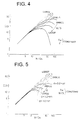
- Fig. 4 shows a relationship between the power consumption W/Q N and the ozone concentration C 03 when the temperature T W of cooling water and the discharge gap length d are kept constant, and the power density W/S is varied. It can be understood that an increase in the power consumption W/S results in the same effect as that obtained by an increase in the temperature T W of cooling water in Fig. 3. This is because the increase in the power consumption W/S and the increase in the temperature T W of cooling water can have the same effect on an increase in the gas temperature in the discharge space 5.
- Fig. 5 shows the ozone concentration C 03 with respect to the power consumption W/Q N when the temperature T W of cooling water and the power density W/S are kept constant, and the discharge gap length d is varied in the range from 0,8 to 1,6 mm.
- An increase in the discharge gap length d can provide an effect which is very similar to the effect obtained by the increase in the temperature T W of cooling water.
- an average gas temperature ⁇ av in the discharge space is defined as the following expression (1)
- another average gas temperature in the discharge space of the ozone generating apparatus in which the only single side of the electrodes is cooled can be represented by the expression (2).
- the expression (3) can be held when both sides of the electrodes are cooled.
- Fig. 6 is a diagram illustrated in Czech, J. Phys., B38, (1988), Fig. 7, p. 648, in which the transverse axis defines the air gap length, and the ordinate axis defines the ozone generating efficiency.
- the symbols o and + respectively represent the results of two cases, that is, one case where air is used as the raw gas and the other case where oxygen is used as the raw gas.
- the article teaches that the optimal air gap length for the ozone generation is in an approximate range of 0.8 to 1.1 mm (see the first line on page 645).
- a narrow air gap of 0.6 mm or less reduces the ozone exciting efficiency.
- the air gap length d is set in the range of 0.8 to 1.5 mm, and a thermal problem is avoided by operation with the power density W/S in a low range. That is, the apparatus is designed to have a large form and have a large discharge area, thereby improving the ozone generating efficiency.
- the conventional ozone generating apparatus is provided as set forth above. As a result, there are problems in that, for example, a low gas temperature in the discharge space should be held, and for this purpose, the power density W/S should be reduced by providing the large ozone generating apparatus and the large discharge area S.
- an ozone generating apparatus in which an elastic body is mounted onto a back face of one of electrodes of an ozone generating unit to cover substantially the entire back face of the electrode.
- the elastic body is mounted onto the back face of one of the electrodes to cover substantially the entire back face of the electrode. Consequently, it is possible to previously avoid breakage of a dielectric and reduction of an air gap accuracy of a discharge space, and realize a stable ozone generating apparatus.
- an ozone generating apparatus in which a spring body is used as an elastic body.
- the elastic body include the spring body. Consequently, it is possible to provide an inexpensive elastic body which can be easily mounted and replaced.
- an ozone generating apparatus in which adjacent an annular spring body is used as an elastic body.
- the elastic body includes the annular spring body. Consequently, it is possible to completely avoid gas leakage.
- an annular portion of an elastic body is partially provided with a gap to discharge air from the elastic body.
- the annular elastic body is partially provided with the gap. Consequently, no stress is applied to an elastic body portion and a dielectric portion even when outside atmospheric pressure is varied.
- an ozone generating apparatus in which an elastic body includes an elastic body made of Kovar material..
- the elastic body is made of Kovar material. Consequently, it is possible to provide the elastic body at low cost.
- an ozone generating apparatus in which, when q d means load applied by an elastic body to a dielectric, the load q d can meet the following expression: q d ⁇ q e x (E d /E e ) x (t d /t e ) 3 where E e means Young's modulus of the electrode, t e is a thickness of the electrode, E d is Young's modulus of the dielectric, t d is a thickness of the dielectric, and q e is a pressure difference applied to the electrode.
- the elastic body is provided so as to apply the load according a predetermined formula to the dielectric. Consequently, it is possible to ensure a gap length without breakage of the dielectric.
- the elastic body is contracted or expanded according to its spring constant by a length found according to a predetermined formula to the dielectric. Consequently, it is possible to ensure a discharge space having a constant air gap length without breakage of the dielectric.
- an ozone generating apparatus in which an elastic body is made of material having ozone resistance.
- the elastic body is made of the material having the ozone resistance. Consequently, it is possible to provide an ozone generating apparatus having high durability.
- an ozone generating apparatus in which fluoroplastic is applied to a partial or entire surface of an elastic body.
- the fluoroplastic is applied to the partial or entire surface of the elastic body. Consequently, it is possible to provide an ozone generating apparatus having high ozone resistance and high durability.
- an ozone generating apparatus in which an elastic body is entirely made of fluoroplastic.
- the elastic body is entirely made of fluoroplastic. Consequently, it is possible to provide an ozone generating apparatus having high ozone resistance and high durability.
- an ozone generating apparatus in which an elastic body is made of ethylene propylene rubber.
- the elastic body is entirely made of ethylene propylene rubber. Consequently, it is possible to provide an ozone generating apparatus having high ozone resistance and high durability.
- an ozone generating apparatus in which an electrode and an elastic body are formed by molding process.
- the electrode and the elastic body are formed by molding process. Consequently, in addition to the effects, it is possible to avoid gas leakage at an elastic body portion.
- an ozone generating apparatus in which an area of an elastic body is kept smaller than that of an electrode, and the elastic body is surrounded by the electrodes at the same potential.
- the elastic body is surrounded by the conductive electrodes. Consequently, no electric field is generated in the elastic body, and material is not degraded due to generation of void discharge.
- an ozone generating apparatus in which, at a rate of one elastic body to a plurality of stacked surfaces of stacked ozone generating units, the elastic body is interposed between the stacked surfaces.
- the elastic body is interposed between the ozone generating units. Consequently, it is possible to previously avoid breakage of a dielectric and reduction of an air gap accuracy of a discharge space, and reduce the number of parts so as to realize cost reduction.
- Fig. 7 is a sectional view showing a first embodiment of the present invention, in which the same reference numerals are used for component parts identical with those in the prior art shown in Figs. 1A and 1B, and descriptions thereof are omitted.
- reference numeral 11 means power supply plates connected to a power source 1 through a fuse 12, and 31 is conduction layers (electrodes) in electrical contact with the power supply plates 11.
- the conduction layer 31 corresponds to a high-voltage electrode 3 in the prior art shown in Figs. 1A and 1B.
- Reference numeral 4 means a dielectric including an alumina ceramics plate.
- reference numeral 32 means a hole (a gas supply mechanism) provided in the ceramics plate 4 at its intermediate portion to serve as a gas passage.
- the conduction layer 31 includes a silver metallized layer mounted on a single side of the ceramics plate 4 to have a thickness of 40 microns. The power supply plate 11 and the conduction layer 31 become at the same potential if the power supply plate 11 is even partially in contact with the conduction layer 31. Therefore, even when any gap is made between the power supply plate 11 and the ceramics plate 4, both of them are kept at the same potential. Accordingly, no electric field is applied to the gap so that no void discharge is caused.
- the conduction layer 31 is formed so as not to cover an entire surface of the ceramics plate 4, and an outer periphery and an inner periphery of the ceramics plate 4 have areas on which no conduction layer 31 is formed. It is thereby possible to prevent creeping discharge toward the grounded electrode 2 through the outer periphery or the inner periphery of the ceramics plate 4 (see Fig. 7). Though a distance required to the creeping discharge between the conduction layer 31 and the grounded electrode 2 depends upon applied voltage, it is typically sufficient to set the distance to 2 mm ore more.
- Reference numeral 61 means a metallic spacer interposed between the grounded electrode 2 and the ceramics plate 4.
- the ceramics plate 4 and the grounded electrode 2 are provided to define, through the spacer 61, a discharge space 5 in which discharge is generated.
- An oxygen-containing gas is supplied through a gas supply port (a gas supply mechanism) 7 into the discharge space 5. Consequently, in the discharge space 5, the oxygen-containing gas is partially ozonized by the discharge caused between the conduction layer 31 and the grounded electrode 2.
- An employed gas may include only oxygen, a mixed gas of nitrogen and oxygen, or air. In this case, as the gas contains the least amount of moisture possible and has the highest oxygen concentration possible, a higher efficiency can be obtained.
- the ceramics plate 4 and the grounded electrode 2 are in surface contact with each other through the metallic spacer 61. Heat generated in the ceramics plate 4 passes through the spacer 61, and can be effectively absorbed by the cooled grounded electrode 2.
- a stress buffer plate (an elastic body) 100 made of ethylene propylene rubber (hereinafter abbreviated EP rubber) having ozone resistance is inserted between the two ozone generating units.
- an unillustrated pressure mechanism is used to press the upper grounded electrode 2 from a direction of the arrow A, thereby assembling an apparatus. That is, the spacer 61 is interposed between the grounded electrode 2 and the ceramics plate 4, and a back of the ceramics plate 4 is pressed by drag of the stress buffer plate 100 serving as the elastic body, thereby keeping a constant air gap length of the discharge gap 5.
- the stress buffer plate 100 absorbs force generated in, for example, the ceramics plate 4 due to mechanical stress or thermal stress. Therefore, the stress buffer plate 100 can prevent degradation of an air gap length accuracy and breakage of the ceramics plate 4, both of which are mainly caused due to distortion of the ceramics plate 4.
- a spacer 6 made of silicone is inserted into a gap defined by electrodes 2 and 3 or ceramics layers (dielectrics) 41 at an outer peripheral portion causing no discharge.
- the air gap length may be varied due to thermal distortion of the electrodes 2 and 3.
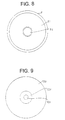
- the stress buffer plate 100 as shown in Fig. 9 is employed in order to avoid the problem.
- reference numeral 100 means the stress buffer plate made of EP rubber
- 101 is an opening (a gas supply mechanism) serving as a gas passage
- 102 is a partial surface of the EP rubber, which is coated with fluoroplastic to avoid corrosion of the EP rubber due to ozone.
- the stress buffer plate 100 has substantially the same size as that of the discharge space 5, and is mounted on a back face of the conduction layer 31 as shown in Fig. 7. It is thereby possible to uniformly dispose the stress buffer plates 100 so as to cover an entire surface of the discharge space 5 from the outside thereof. Further, it is possible to ensure the air gap length of the spacer 61, and keep a high air gap length accuracy of the discharge space 5. That is, in the structure in the embodiment, the air gap length can be left constant even when a thickness of the ceramics plate 4 is varied due to, for example, thermal expansion, and a thickness of the stress buffer plate 100 is varied to buffer the variation.
- the structure in the embodiment is effective particularly when a very short air gap of about several hundreds microns is required.
- the air gap is held between the high-voltage conduction layers 31 at the same potential to be surrounded by the conduction layers 31.
- the stress buffer plate 100 preferably has an area equal to or less than that of the conduction layer 31 applied onto the surface of the ceramics plate 4, and the stress buffer plate 100 is preferably surrounded by the conduction layers 31 at the same potential.
- the stress buffer plate 100 may be entirely made of fluoroplastic.
- a gas may leak from between the stress buffer plates 100, or between the stress buffer plate 100 and the ceramics plate 4.
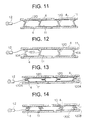
- a gap between ceramics plates 4 may be integrally molded by an elastic material 110 such as filter material made of silicone rubber, thereby eliminating the problem of the gas leakage. Since the integral molding is not required for the ceramics plates 4, only the stress buffer plate 100 and a power supply plate 11 may be molded, thereby avoiding the gas leakage from a gap between stress buffer plates 100.
- a conduction layer 31 interposed between a power supply plate 11 and the ceramics plate 4 is not shown.
- spring-like metallic rings (elastic bodies) 120 such as bellows may be inserted into a gap between two ceramic plates 4, and power supply plates 11 mounted on surfaces of unillustrated conduction layers 31 may be jointed to circumferential portions of the metallic rings 120. It is thereby possible to completely avoid gas leakage, and sufficiently provide a stress buffer effect.
- the metallic ring 120 includes two kinds of Kovar materials having a thickness of 0.5 mm and each different diameter, and upper and lower circumferential portions thereof are jointed to the conduction layers 31 formed on the dielectric plates 4.
- an inner space surrounded by both ring portions of the metallic ring 120 is sealed completely.
- stress may be generated with respect to both the ring portions and the dielectric plates 4 according to a variation in outside atmospheric pressure.
- an outer ring portion of the metallic ring 120 may be jointed to dielectric layers 31 so as not to establish complete sealing, and spot joint may be made to provide an air escape hole (a gap). The spot joint at the outer ring portion is required because an active ozone gas is present at an intermediate portion of the dielectric plate 4.
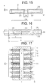
- a side wall of a metallic ring 120 may be partially provided with an air escape hole 10A (a gap).
- an outer ring portion is preferably partially provided with the air escape hole 10A.
- a side wall of a metallic ring 120 may be provided in a form having an intermediate folded portion 120A. It is thereby possible to adjust an elastic constant of the metallic ring 120 to the optimal value.
- a side wall of a metallic ring 120 may be provided to have a plurality of folded portions 120B and 120C as viewed in a sectional form. It is also possible to adjust an elastic constant of the metallic ring 120 to the optimal value.
- an annular member is employed as the metallic ring 120 according to disk-like shapes of electrode portions such as the conduction layer 31 including the ceramics plate 4, or the power supply plate 11.
- the electrode portions such as the ceramics plate 4, the conduction layer 31, and the power supply plate 11 may include plate members having a polygonal form such as a triangle form, or a quadrangular form.
- the metallic ring 120 should be provided in a hollow polygonal form such as a hollow triangle pole or a hollow square pole according to the form of the electrode.
- a cavity 23 (a water channel) is provided in a grounded electrode 2 to pass cooling water, but not shown in the drawings as described above.
- An upper plate (an electrode) 24 is mounted on an upper surface of the cavity 23 to provide a constant air gap length of a discharge space in an ozone generating apparatus.
- component parts including a spacer 61, a ceramics plate 4, a conduction layer 31, a power supply plate 11, a stress buffer plate 100, and so forth.
- the ozone generating apparatus is generally operated while passing a high-pressure gas at a pressure of 1.5 atm or more. Hence, a pressure difference may be caused between a gas passage above the upper plate 24 and the cooling water channel under the upper plate 24, and the upper plate 24 my be deflected toward the side of the cavity 23 as shown in Fig. 15.
- ⁇ K 1 x qa 4 /D
- D Et 3 / ⁇ 12(1-v 2 ) ⁇
- q load (kg/cm 2 ) of the upper plate 24
- E Young's modulus (kg/cm 2 )
- v Poisson's ratio of the upper plate
- b is a radius (cm) of an inner circle of the upper plate 24 and a is a radius (cm) of an outer circle of the upper plate 24
- K 1 is equal to 0.006 (see Raymond J. Roark and W. C. Young, Formulas for Stress and Strain, 5 th ed., International Editions, McGraw-Hill, [1986], p. 339).
- the amount of deflection ⁇ can be reduced by increasing the thickness t of the upper plate 24.
- the grounded electrode 2 is typically made of stainless having low coefficient of heat transfer, an increase in the thickness t results in a hot upper plate 24.
- the discharge gap length may be varied, and ozone generating characteristics such as ozone generating efficiency ⁇ may be degraded.
- the deflection of the upper plate 24 can be offset by providing deflection for the ceramics plate 4 (see Fig. 7) opposed to the upper plate 24 according to the deflection of the upper plate 24.
- an urging member having repulsion such as a metallic ring 120, may be mounted on a back face of the ceramics plate 4, thereby applying load to the ceramics plate 4.
- the load q d may meet the following expression with respect to the pressure difference q e : q d ⁇ q e x (E d /E e ) x (t d /t e ) 3
- the load q d becomes an extremely larger value than a value meeting the above expression, the ceramics plate 4 is broken.
- the load q d becomes an extremely smaller value, it is impossible to keep a constant air gap length of the discharge space.
- the load q d may be a value in an approximate range of 0.1 to 0.5 kg/cm 2 .
- two (metallic) ring members 26, 26 having each different diameter may be made of metal having high coefficient of heat transfer such as copper, and a grounded electrode 2 may be structured by interposing the two ring members 26, 26 between two stainless plates (metallic plates) 25, 25. It is thereby possible to efficiently cool the stainless plates 25 through the ring members 26, 26 having high coefficient of heat transfer. Therefore, in the design, a radius a of an outer circle of a cavity 23 can be made smaller, and a radius b of an inner circle thereof can be made larger, that is, the volume of the cavity 23 can be made smaller. It is thereby possible to maintain high mechanical strength of the grounded electrode 2 even when a thickness of the stainless plate 25 is reduced. In such a structure, a heat removing efficiency can be improved by brazed joint between the stainless plate 25 and the ring member 26, that is, by pouring brazing material to a contact surface between the stainless plate 25 and the ring member 26.
- the stress buffer plate 100 may be used for a small-capacity ozone generating apparatus including a single discharge space, resulting in the same effect. That is, one stress buffer plate 100 is used for an ozone generating apparatus including one ozone generating unit having a structure identical with a lower half of a structure shown in Fig. 7. It is thereby possible to provide the above effects such as maintenance of an air gap length of the discharge space, or prevention of breakage of a dielectric in the ozone generating apparatus.
- a stress buffer plate is not always required for a ozone generating unit. Further, as shown in Fig. 17, some effects can be obtained by simply providing only one stress buffer plate 100 for a plurality of ozone generating units 10. This provides the effects in that, for example the number of parts can be reduced an gas leakage from the stress buffer plate 100 can be avoided.
- the elastic body may be mounted onto the back face of one of the electrodes to cover substantially the entire back face of the electrode.
- the elastic body may include the spring body.
- the elastic body may include an annular spring body.
- a gap may be partially provided in the annular elastic body.
- the elastic body may be made of Kovar material. As a result, there is an effect in that the elastic body can be provided at low cost.
- the elastic body may be provided so as to apply the load according a predetermined formula to the dielectric.
- the elastic body may be contracted or expanded according to its spring constant by a length found according to a predetermined formula to apply the load according to a predetermined formula to the dielectric.
- the elastic body may be made of the material having ozone resistance. As a result, there is an effect that an ozone generating apparatus can be provided to have high durability.
- fluoroplastic may be applied to a partial or entire surface of the elastic body.
- the elastic body may be entirely made of fluoroplastic. As a result, there is an effect in that an ozone generating apparatus can be provided to have high ozone resistance and high durability.
- the elastic body may be made of ethylene propylene rubber.
- the electrode and the elastic body may be formed by molding process.
- the elastic body may be surrounded by the electrodes at the same potential.
- the elastic body may be interposed between the ozone generating units.
Landscapes
- Chemical & Material Sciences (AREA)
- Organic Chemistry (AREA)
- Inorganic Chemistry (AREA)
- Oxygen, Ozone, And Oxides In General (AREA)
Applications Claiming Priority (7)
| Application Number | Priority Date | Filing Date | Title |
|---|---|---|---|
| JP9271894 | 1994-04-28 | ||
| JP92718/94 | 1994-04-28 | ||
| JP9271894 | 1994-04-28 | ||
| JP47647/95 | 1995-03-07 | ||
| JP4764795 | 1995-03-07 | ||
| JP7047647A JP2983153B2 (ja) | 1994-04-28 | 1995-03-07 | オゾン発生装置 |
| EP95106162A EP0679608B1 (de) | 1994-04-28 | 1995-04-25 | Verfahren zur Erzeugung von Ozon |
Related Parent Applications (1)
| Application Number | Title | Priority Date | Filing Date |
|---|---|---|---|
| EP95106162A Division EP0679608B1 (de) | 1994-04-28 | 1995-04-25 | Verfahren zur Erzeugung von Ozon |
Publications (2)
| Publication Number | Publication Date |
|---|---|
| EP0893405A2 true EP0893405A2 (de) | 1999-01-27 |
| EP0893405A3 EP0893405A3 (de) | 1999-07-07 |
Family
ID=26387814
Family Applications (6)
| Application Number | Title | Priority Date | Filing Date |
|---|---|---|---|
| EP98250367A Withdrawn EP0893406A3 (de) | 1994-04-28 | 1995-04-24 | Vorrichtung zur Erzeugung von Ozon |
| EP98250368A Withdrawn EP0891941A3 (de) | 1994-04-28 | 1995-04-24 | Vorrichtung zur Erzeugung von Ozon |
| EP98250366A Withdrawn EP0893405A3 (de) | 1994-04-28 | 1995-04-25 | Vorrichtung zur Erzeugung von Ozon |
| EP95106162A Expired - Lifetime EP0679608B1 (de) | 1994-04-28 | 1995-04-25 | Verfahren zur Erzeugung von Ozon |
| EP07012353A Withdrawn EP1829823A3 (de) | 1994-04-28 | 1995-04-25 | Vorrichtung zur Erzeugung von Ozon |
| EP00114881.6A Expired - Lifetime EP1069071B1 (de) | 1994-04-28 | 1995-04-25 | Vorrichtung zur Erzeugung von Ozon |
Family Applications Before (2)
| Application Number | Title | Priority Date | Filing Date |
|---|---|---|---|
| EP98250367A Withdrawn EP0893406A3 (de) | 1994-04-28 | 1995-04-24 | Vorrichtung zur Erzeugung von Ozon |
| EP98250368A Withdrawn EP0891941A3 (de) | 1994-04-28 | 1995-04-24 | Vorrichtung zur Erzeugung von Ozon |
Family Applications After (3)
| Application Number | Title | Priority Date | Filing Date |
|---|---|---|---|
| EP95106162A Expired - Lifetime EP0679608B1 (de) | 1994-04-28 | 1995-04-25 | Verfahren zur Erzeugung von Ozon |
| EP07012353A Withdrawn EP1829823A3 (de) | 1994-04-28 | 1995-04-25 | Vorrichtung zur Erzeugung von Ozon |
| EP00114881.6A Expired - Lifetime EP1069071B1 (de) | 1994-04-28 | 1995-04-25 | Vorrichtung zur Erzeugung von Ozon |
Country Status (5)
| Country | Link |
|---|---|
| US (3) | US5759497A (de) |
| EP (6) | EP0893406A3 (de) |
| JP (1) | JP2983153B2 (de) |
| CA (1) | CA2147534C (de) |
| DE (1) | DE69527469T2 (de) |
Families Citing this family (67)
| Publication number | Priority date | Publication date | Assignee | Title |
|---|---|---|---|---|
| GB2320172B (en) * | 1994-12-13 | 1999-03-31 | William Alan Burris | Ozone generator |
| US5529760A (en) * | 1994-12-13 | 1996-06-25 | Burris; William A. | Ozone generator |
| FR2731692B1 (fr) * | 1994-12-13 | 1997-10-24 | Burris William Alan | Generateur d'ozone, ensemble etablissant un entrefer, et ensemble d'uniformisation pour generateur d'ozone |
| US5700505A (en) * | 1995-12-28 | 1997-12-23 | Mei Research, Inc. | Method of improving head rice yield |
| JPH1025104A (ja) * | 1996-07-10 | 1998-01-27 | Mitsubishi Electric Corp | オゾン発生装置 |
| JP3654409B2 (ja) * | 1998-03-24 | 2005-06-02 | 住友精密工業株式会社 | オゾン発生装置用放電セル及びその製造方法 |
| WO2000032514A1 (fr) * | 1998-12-01 | 2000-06-08 | Mitsubishi Denki Kabushiki Kaisha | Generateur d'ozone |
| JP2007197318A (ja) * | 1999-01-29 | 2007-08-09 | Sumitomo Precision Prod Co Ltd | オゾン発生装置用放電セル |
| JP2009179556A (ja) * | 1999-01-29 | 2009-08-13 | Sumitomo Precision Prod Co Ltd | オゾン発生装置用放電セル及びその放電セルを使用したオゾン発生装置 |
| JP2004224695A (ja) * | 1999-01-29 | 2004-08-12 | Sumitomo Precision Prod Co Ltd | オゾン発生装置用放電セル |
| JP2006169110A (ja) * | 1999-01-29 | 2006-06-29 | Sumitomo Precision Prod Co Ltd | オゾン発生装置用放電セル |
| US6146599A (en) | 1999-02-24 | 2000-11-14 | Seagate Technology Llc | Dielectric barrier discharge system and method for decomposing hazardous compounds in fluids |
| SE514694C2 (sv) | 1999-03-05 | 2001-04-02 | Ozonator Ltd | Anordning och förfarande för generering av ozon där tryckförändringar utjämnas |
| US6633055B2 (en) * | 1999-04-30 | 2003-10-14 | International Business Machines Corporation | Electronic fuse structure and method of manufacturing |
| US6451252B1 (en) * | 2000-01-20 | 2002-09-17 | Regents Of The University Of Minnesota | Odor removal system and method having ozone and non-thermal plasma treatment |
| EP1291320A4 (de) * | 2000-06-09 | 2006-06-07 | Sumitomo Prec Products Company | Entladungszelle für ozongeneratoren |
| US6599486B1 (en) | 2000-09-15 | 2003-07-29 | Ozonator, Ltd. | Modular ozone generator system |
| JP4095758B2 (ja) | 2000-06-29 | 2008-06-04 | 株式会社荏原製作所 | オゾン発生装置 |
| US7011790B2 (en) * | 2001-05-07 | 2006-03-14 | Regents Of The University Of Minnesota | Non-thermal disinfection of biological fluids using non-thermal plasma |
| US6911225B2 (en) * | 2001-05-07 | 2005-06-28 | Regents Of The University Of Minnesota | Method and apparatus for non-thermal pasteurization of living-mammal-instillable liquids |
| US6562386B2 (en) | 2001-05-07 | 2003-05-13 | Regents Of The University Of Minnesota | Method and apparatus for non-thermal pasteurization |
| RU2187910C1 (ru) * | 2001-06-26 | 2002-08-20 | Мордовский государственный университет им. Н.П.Огарева | Устройство барьерного разряда |
| US20030030374A1 (en) * | 2001-08-03 | 2003-02-13 | Deepak Pai | Dielectric barrier discharge plasma reactor cell |
| WO2003019763A1 (en) * | 2001-08-25 | 2003-03-06 | Lg Electronics Inc. | Electrodynamic energy converter and refringerating plant based thereon |
| JP3607890B2 (ja) | 2001-11-22 | 2005-01-05 | 東芝三菱電機産業システム株式会社 | オゾン発生器 |
| JP3513134B2 (ja) | 2001-11-22 | 2004-03-31 | 三菱電機株式会社 | オゾン発生器 |
| JP3641608B2 (ja) | 2001-11-22 | 2005-04-27 | 東芝三菱電機産業システム株式会社 | オゾン発生器 |
| JP3672252B2 (ja) | 2001-11-22 | 2005-07-20 | 東芝三菱電機産業システム株式会社 | オゾン発生器 |
| US7029637B2 (en) | 2003-01-09 | 2006-04-18 | H203, Inc. | Apparatus for ozone production, employing line and grooved electrodes |
| US20040136885A1 (en) * | 2003-01-09 | 2004-07-15 | Hogarth Derek J. | Apparatus and method for generating ozone |
| US6817356B2 (en) | 2003-04-18 | 2004-11-16 | Arlen W. Gallagher | Method and apparatus for removal of grease, smoke and odor from exhaust systems |
| JP2005137781A (ja) * | 2003-11-10 | 2005-06-02 | Marcom:Kk | プラズマ発生装置 |
| TW200528390A (en) * | 2004-02-25 | 2005-09-01 | Toshiba Mitsubishi Elec Inc | Apparatus and method of producing ozone gas |
| JP4320637B2 (ja) | 2004-04-08 | 2009-08-26 | 三菱電機株式会社 | オゾン発生装置およびオゾン発生方法 |
| JP4515856B2 (ja) * | 2004-08-09 | 2010-08-04 | 住友精密工業株式会社 | 放電セル用冷却器 |
| US20060130663A1 (en) * | 2004-12-20 | 2006-06-22 | General Electric Company | System and method of air quality control for air-conditioning devices |
| JP2007084403A (ja) * | 2005-09-26 | 2007-04-05 | Sumitomo Precision Prod Co Ltd | オゾン発生装置用放電セル |
| JP4925087B2 (ja) * | 2005-10-28 | 2012-04-25 | 三菱電機株式会社 | オゾン発生器 |
| FR2898520B1 (fr) * | 2006-03-20 | 2008-06-27 | Green Technologies Sarl | Nouveau procede de depelliculage du grain de ble |
| EP1882673A1 (de) * | 2006-07-28 | 2008-01-30 | Liou, Huei-Tarng | Ozongenerator |
| US7931811B2 (en) * | 2006-10-27 | 2011-04-26 | Regents Of The University Of Minnesota | Dielectric barrier reactor having concentrated electric field |
| FR2939123B1 (fr) * | 2008-12-01 | 2011-01-07 | Renault Sas | Unite generatrice d'ozone et module generateur d'ozone pour systeme de climatisation d'un vehicule automobile |
| JP5048714B2 (ja) * | 2009-05-19 | 2012-10-17 | 三菱電機株式会社 | オゾン発生装置 |
| TW201109475A (en) * | 2009-09-03 | 2011-03-16 | ming-yong Xu | Sealed film electrode electrolytic ozone generator |
| TW201109474A (en) * | 2009-09-03 | 2011-03-16 | ming-yong Xu | Film electrode electrolytic ozone generator |
| US20130224084A1 (en) * | 2010-11-09 | 2013-08-29 | Episolutions Co., Ltd. | Ozone generating device |
| CA2832718C (en) | 2011-04-13 | 2016-12-13 | Mitsubishi Electric Corporation | Ozone generation system and method for operating ozone generation system |
| US9039985B2 (en) | 2011-06-06 | 2015-05-26 | Mks Instruments, Inc. | Ozone generator |
| JP5728356B2 (ja) * | 2011-10-18 | 2015-06-03 | 株式会社東芝 | 気流発生ユニット、気流発生ユニットの設置方法および風力発電装置 |
| CN102502514B (zh) * | 2011-10-24 | 2013-04-17 | 罗璐 | 一种用于构建层叠结构式低温等离子反应体的单元模块 |
| JP2013094711A (ja) * | 2011-10-31 | 2013-05-20 | Sharp Corp | オゾン液生成装置 |
| CA2856196C (en) | 2011-12-06 | 2020-09-01 | Masco Corporation Of Indiana | Ozone distribution in a faucet |
| JP5677344B2 (ja) * | 2012-03-16 | 2015-02-25 | 株式会社東芝 | オゾン発生装置 |
| JP5693787B2 (ja) | 2012-04-05 | 2015-04-01 | 三菱電機株式会社 | オゾン発生システムおよびオゾン発生方法 |
| US10695740B2 (en) * | 2013-11-25 | 2020-06-30 | Imalog Inc. | Method and device for controlling an ozone generator power supply |
| WO2016067382A1 (ja) | 2014-10-29 | 2016-05-06 | 東芝三菱電機産業システム株式会社 | オゾン発生装置 |
| WO2016132919A1 (ja) | 2015-02-19 | 2016-08-25 | 三菱電機株式会社 | オゾン発生装置 |
| CA2992280C (en) | 2015-07-13 | 2022-06-21 | Delta Faucet Company | Electrode for an ozone generator |
| CA2946465C (en) | 2015-11-12 | 2022-03-29 | Delta Faucet Company | Ozone generator for a faucet |
| WO2017112795A1 (en) | 2015-12-21 | 2017-06-29 | Delta Faucet Company | Fluid delivery system including a disinfectant device |
| SE540004C2 (en) * | 2016-08-05 | 2018-02-20 | Ozone Inventions Ltd | OZONE GENERATOR UNIT AND SYSTEM |
| US10143763B2 (en) | 2016-10-06 | 2018-12-04 | Alfonso Campalans | Neutral atmosphere and sanitization storage apparatus, method and system |
| CN111517285A (zh) * | 2019-02-01 | 2020-08-11 | 华贸中经环保科技(天津)有限公司 | 一种用于臭氧发生器的板式地电极 |
| SE547358C2 (en) * | 2021-09-28 | 2025-07-15 | Arrow Lake Ab | Plate-type ozone generator and system for generating ozone |
| CN114394576A (zh) * | 2022-01-24 | 2022-04-26 | 深圳市科尔诺电子科技有限公司 | 双极冷却可组合板式臭氧发生器 |
| JP7846562B2 (ja) * | 2022-05-27 | 2026-04-15 | 株式会社キッツ | オゾナイザ及びオゾン発生システム |
| JP7789248B1 (ja) * | 2025-03-27 | 2025-12-19 | 住友精密工業株式会社 | オゾンガス発生用放電セル及びその製造方法 |
Family Cites Families (31)
| Publication number | Priority date | Publication date | Assignee | Title |
|---|---|---|---|---|
| US3010892A (en) * | 1956-05-22 | 1961-11-28 | Axt Gunter | Ozone generating apparatus |
| US3309304A (en) * | 1963-04-30 | 1967-03-14 | Caplan Benjamin | Ozone generators |
| US3903426A (en) * | 1967-01-04 | 1975-09-02 | Purification Sciences Inc | Corona generator electrode |
| US3996474A (en) * | 1967-01-04 | 1976-12-07 | Purification Sciences, Inc. | Corona generator apparatus |
| US3742301A (en) * | 1972-05-11 | 1973-06-26 | W Burris | Corona generator |
| US4213838A (en) * | 1973-08-13 | 1980-07-22 | Union Carbide Corporation | Corona reaction system |
| JPS51110494A (ja) * | 1975-03-25 | 1976-09-30 | Mitsubishi Electric Corp | Ozonhatsuseisochi |
| US4049707A (en) * | 1976-02-20 | 1977-09-20 | O-3 Company | Apparatus for fluid treatment by corona discharge |
| JPS5354190A (en) * | 1976-10-27 | 1978-05-17 | Hitachi Ltd | Ozonizer |
| US4232229A (en) * | 1978-02-13 | 1980-11-04 | Mitsubishi Denki Kabushiki Kaisha | Ozonizer |
| JPS5575905A (en) * | 1978-11-30 | 1980-06-07 | Takaoka Ind Ltd | Ozone generating tube |
| DE2925667A1 (de) * | 1979-05-22 | 1980-12-04 | Bbc Brown Boveri & Cie | Vorrichtung zur erzeugung von ozon |
| DE2932346A1 (de) * | 1979-07-12 | 1981-02-05 | Bbc Brown Boveri & Cie | Ozonisator |
| DE3247374A1 (de) * | 1982-12-22 | 1984-07-05 | Bruno Bachhofer | Ozonerzeuger mit plattenfoermigen hochspannungs-elektroden |
| US4603031A (en) * | 1985-05-28 | 1986-07-29 | Gelbman Howard A | Ozone generator |
| US4908189A (en) * | 1988-07-15 | 1990-03-13 | Henkel Corporation | Concentric tube ozonator |
| CH676844A5 (de) * | 1988-09-09 | 1991-03-15 | Asea Brown Boveri | |
| US4960569A (en) * | 1988-11-14 | 1990-10-02 | Alten Corporation | Corona discharge ozonator with cooled flow path |
| US4970056A (en) * | 1989-01-18 | 1990-11-13 | Fusion Systems Corporation | Ozone generator with improved dielectric and method of manufacture |
| JPH0678592B2 (ja) * | 1990-03-16 | 1994-10-05 | 株式会社オーディーエス | オゾン水製造装置 |
| CH680510A5 (de) * | 1990-03-28 | 1992-09-15 | Ozonia Ag | |
| KR920008813Y1 (ko) * | 1990-07-09 | 1992-12-19 | 삼성전자 주식회사 | 오존발생장치가 내장된 수도직결식 정수기 |
| JPH0734389B2 (ja) * | 1990-10-17 | 1995-04-12 | 住友精密工業株式会社 | 被覆細線極型活性種発生装置 |
| US5516493A (en) * | 1991-02-21 | 1996-05-14 | Bell; Maxwell G. | Method and apparatus for producing ozone by corona discharge |
| JP2564715B2 (ja) * | 1991-08-08 | 1996-12-18 | 住友精密工業株式会社 | プレート型オゾン発生機 |
| DE4141025C2 (de) * | 1991-12-12 | 1996-01-18 | Manfred Prof Dr Rer Na Rimpler | Vorrichtung zur Erzeugung von Ozon |
| US5549874A (en) * | 1992-04-23 | 1996-08-27 | Ebara Corporation | Discharge reactor |
| US5538695A (en) * | 1992-07-03 | 1996-07-23 | Ebara Corporation | Ozonizer |
| US5503809A (en) * | 1993-04-19 | 1996-04-02 | John T. Towles | Compact ozone generator |
| US5637279A (en) * | 1994-08-31 | 1997-06-10 | Applied Science & Technology, Inc. | Ozone and other reactive gas generator cell and system |
| US5529760A (en) * | 1994-12-13 | 1996-06-25 | Burris; William A. | Ozone generator |
-
1995
- 1995-03-07 JP JP7047647A patent/JP2983153B2/ja not_active Expired - Lifetime
- 1995-04-17 US US08/422,900 patent/US5759497A/en not_active Expired - Lifetime
- 1995-04-21 CA CA002147534A patent/CA2147534C/en not_active Expired - Lifetime
- 1995-04-24 EP EP98250367A patent/EP0893406A3/de not_active Withdrawn
- 1995-04-24 EP EP98250368A patent/EP0891941A3/de not_active Withdrawn
- 1995-04-25 EP EP98250366A patent/EP0893405A3/de not_active Withdrawn
- 1995-04-25 DE DE69527469T patent/DE69527469T2/de not_active Expired - Lifetime
- 1995-04-25 EP EP95106162A patent/EP0679608B1/de not_active Expired - Lifetime
- 1995-04-25 EP EP07012353A patent/EP1829823A3/de not_active Withdrawn
- 1995-04-25 EP EP00114881.6A patent/EP1069071B1/de not_active Expired - Lifetime
-
1997
- 1997-09-29 US US08/939,989 patent/US5948374A/en not_active Expired - Lifetime
-
1998
- 1998-12-22 US US09/219,904 patent/US6093289A/en not_active Expired - Lifetime
Also Published As
| Publication number | Publication date |
|---|---|
| US5759497A (en) | 1998-06-02 |
| EP0679608B1 (de) | 2002-07-24 |
| EP0893406A3 (de) | 1999-07-07 |
| CA2147534C (en) | 2000-11-07 |
| EP1829823A3 (de) | 2010-01-20 |
| US6093289A (en) | 2000-07-25 |
| EP0893406A2 (de) | 1999-01-27 |
| EP0891941A2 (de) | 1999-01-20 |
| EP0679608A2 (de) | 1995-11-02 |
| US5948374A (en) | 1999-09-07 |
| JPH0812304A (ja) | 1996-01-16 |
| EP0679608A3 (de) | 1997-11-19 |
| EP1069071A2 (de) | 2001-01-17 |
| DE69527469T2 (de) | 2003-04-03 |
| DE69527469D1 (de) | 2002-08-29 |
| EP1829823A2 (de) | 2007-09-05 |
| JP2983153B2 (ja) | 1999-11-29 |
| EP1069071A3 (de) | 2006-09-27 |
| EP0893405A3 (de) | 1999-07-07 |
| EP0891941A3 (de) | 1999-07-07 |
| EP1069071B1 (de) | 2014-05-07 |
| CA2147534A1 (en) | 1995-10-29 |
Similar Documents
| Publication | Publication Date | Title |
|---|---|---|
| EP0893405A2 (de) | Vorrichtung zur Erzeugung von Ozon | |
| US5417936A (en) | Plate-type ozone generator | |
| JP3803401B2 (ja) | オゾン発生装置 | |
| US6726885B2 (en) | Ozone generator and a method for generation of ozone | |
| US20020001550A1 (en) | Ozone generator | |
| AU604908B2 (en) | Resilient dielectric electrode for corona discharge devices | |
| US6016023A (en) | Tubular ultrasonic transducer | |
| US20060138957A1 (en) | Plasma generating electrode and plasma reactor | |
| US4882129A (en) | Ozone generator cell | |
| US6284203B1 (en) | Ozonizer discharge cell and its manufacturing method | |
| JP3513134B2 (ja) | オゾン発生器 | |
| JP3545257B2 (ja) | オゾン発生装置およびオゾン発生方法 | |
| JP3592700B2 (ja) | オゾン発生装置 | |
| CA2298925C (en) | Ozone generating apparatus | |
| JPH057835B2 (de) | ||
| JP2556805B2 (ja) | プレ−ト型オゾン発生装置 | |
| JP3804229B2 (ja) | オゾナイザ | |
| JP2002160906A (ja) | オゾン発生器 | |
| EP1882673A1 (de) | Ozongenerator | |
| JP2003327415A (ja) | オゾン発生装置 | |
| JP2005041778A (ja) | オゾン発生装置 | |
| JPH03208383A (ja) | ガスレーザ装置 | |
| JPH08133704A (ja) | プレ−ト型オゾン発生装置 |
Legal Events
| Date | Code | Title | Description |
|---|---|---|---|
| PUAI | Public reference made under article 153(3) epc to a published international application that has entered the european phase |
Free format text: ORIGINAL CODE: 0009012 |
|
| 17P | Request for examination filed |
Effective date: 19981019 |
|
| AC | Divisional application: reference to earlier application |
Ref document number: 679608 Country of ref document: EP |
|
| AK | Designated contracting states |
Kind code of ref document: A2 Designated state(s): DE FR GB IT |
|
| PUAL | Search report despatched |
Free format text: ORIGINAL CODE: 0009013 |
|
| AK | Designated contracting states |
Kind code of ref document: A3 Designated state(s): DE FR GB IT |
|
| RAP1 | Party data changed (applicant data changed or rights of an application transferred) |
Owner name: MITSUBISHI DENKI KABUSHIKI KAISHA |
|
| STAA | Information on the status of an ep patent application or granted ep patent |
Free format text: STATUS: THE APPLICATION IS DEEMED TO BE WITHDRAWN |
|
| 18D | Application deemed to be withdrawn |
Effective date: 20141101 |