EP0893524A1 - Organe d'insertion de trame pour métier à tisser à pinces - Google Patents
Organe d'insertion de trame pour métier à tisser à pinces Download PDFInfo
- Publication number
- EP0893524A1 EP0893524A1 EP98112299A EP98112299A EP0893524A1 EP 0893524 A1 EP0893524 A1 EP 0893524A1 EP 98112299 A EP98112299 A EP 98112299A EP 98112299 A EP98112299 A EP 98112299A EP 0893524 A1 EP0893524 A1 EP 0893524A1
- Authority
- EP
- European Patent Office
- Prior art keywords
- weft
- wall
- inserting apparatus
- guide frame
- set forth
- Prior art date
- Legal status (The legal status is an assumption and is not a legal conclusion. Google has not performed a legal analysis and makes no representation as to the accuracy of the status listed.)
- Withdrawn
Links
- 230000007246 mechanism Effects 0.000 claims abstract description 21
- 230000001105 regulatory effect Effects 0.000 claims abstract description 14
- 239000002184 metal Substances 0.000 claims description 20
- 238000005452 bending Methods 0.000 claims description 16
- 229910000831 Steel Inorganic materials 0.000 claims description 13
- 238000005266 casting Methods 0.000 claims description 13
- 238000010310 metallurgical process Methods 0.000 claims description 13
- 239000010959 steel Substances 0.000 claims description 13
- 235000014676 Phragmites communis Nutrition 0.000 claims description 7
- 239000002759 woven fabric Substances 0.000 claims description 6
- 239000004744 fabric Substances 0.000 claims description 5
- 125000006850 spacer group Chemical group 0.000 claims description 5
- 230000003014 reinforcing effect Effects 0.000 claims description 4
- 238000003780 insertion Methods 0.000 claims description 2
- 230000037431 insertion Effects 0.000 claims description 2
- 239000000463 material Substances 0.000 claims description 2
- 229920003002 synthetic resin Polymers 0.000 claims description 2
- 239000000057 synthetic resin Substances 0.000 claims description 2
- 230000009471 action Effects 0.000 abstract description 9
- 238000000034 method Methods 0.000 description 24
- 230000008569 process Effects 0.000 description 23
- 238000001746 injection moulding Methods 0.000 description 14
- 238000005245 sintering Methods 0.000 description 14
- 238000004519 manufacturing process Methods 0.000 description 10
- 230000000694 effects Effects 0.000 description 5
- 230000008901 benefit Effects 0.000 description 3
- 230000006872 improvement Effects 0.000 description 3
- 230000015572 biosynthetic process Effects 0.000 description 2
- 238000007493 shaping process Methods 0.000 description 2
- 238000005299 abrasion Methods 0.000 description 1
- 230000008859 change Effects 0.000 description 1
- 239000000470 constituent Substances 0.000 description 1
- 230000003247 decreasing effect Effects 0.000 description 1
- 239000007769 metal material Substances 0.000 description 1
- 238000012986 modification Methods 0.000 description 1
- 230000004048 modification Effects 0.000 description 1
- 230000002459 sustained effect Effects 0.000 description 1
Images




Classifications
-
- D—TEXTILES; PAPER
- D03—WEAVING
- D03D—WOVEN FABRICS; METHODS OF WEAVING; LOOMS
- D03D47/00—Looms in which bulk supply of weft does not pass through shed, e.g. shuttleless looms, gripper shuttle looms, dummy shuttle looms
- D03D47/12—Looms in which bulk supply of weft does not pass through shed, e.g. shuttleless looms, gripper shuttle looms, dummy shuttle looms wherein single picks of weft thread are inserted, i.e. with shedding between each pick
- D03D47/20—Constructional features of the thread-engaging device on the inserters
- D03D47/23—Thread grippers
- D03D47/233—Carrying grippers
-
- D—TEXTILES; PAPER
- D03—WEAVING
- D03D—WOVEN FABRICS; METHODS OF WEAVING; LOOMS
- D03D47/00—Looms in which bulk supply of weft does not pass through shed, e.g. shuttleless looms, gripper shuttle looms, dummy shuttle looms
- D03D47/12—Looms in which bulk supply of weft does not pass through shed, e.g. shuttleless looms, gripper shuttle looms, dummy shuttle looms wherein single picks of weft thread are inserted, i.e. with shedding between each pick
- D03D47/20—Constructional features of the thread-engaging device on the inserters
- D03D47/23—Thread grippers
-
- D—TEXTILES; PAPER
- D03—WEAVING
- D03D—WOVEN FABRICS; METHODS OF WEAVING; LOOMS
- D03D47/00—Looms in which bulk supply of weft does not pass through shed, e.g. shuttleless looms, gripper shuttle looms, dummy shuttle looms
- D03D47/27—Drive or guide mechanisms for weft inserting
- D03D47/271—Rapiers
-
- D—TEXTILES; PAPER
- D03—WEAVING
- D03D—WOVEN FABRICS; METHODS OF WEAVING; LOOMS
- D03D49/00—Details or constructional features not specially adapted for looms of a particular type
- D03D49/24—Mechanisms for inserting shuttle in shed
- D03D49/50—Miscellaneous devices or arrangements concerning insertion of weft and not otherwise provided for
-
- D—TEXTILES; PAPER
- D03—WEAVING
- D03J—AUXILIARY WEAVING APPARATUS; WEAVERS' TOOLS; SHUTTLES
- D03J1/00—Auxiliary apparatus combined with or associated with looms
- D03J1/04—Auxiliary apparatus combined with or associated with looms for treating weft
Definitions
- the present invention relates generally to a weft inserting apparatus for a rapier loom. More particularly, the invention is concerned with a weft feeding rapier head of a weft inserting apparatus which can ensure a smooth yarn guiding action.
- a weft feeding head disclosed in Japanese Patent Laid-open No. 4-214439 (functionally corresponding to the weft feeding rapier head according to the present invention) is comprised of a base portion and a main body (functionally corresponding to a guide frame of the weft feeding rapier head according to the invention), wherein the main body includes a pair of side walls.
- a gripper for holding a weft is fixedly secured to the base portion in such disposition that the weft guided along upper edges of the paired side walls can be introduced into a gripping portion of the gripper.
- the gripper is constituted by a rigid clamp jaw equipped with a weft deflecting fin and a resilient tongue member, wherein the weft is held between the rigid clamp jaw and the resilient tongue member.
- the tip end portion of the resilient clamp jaw is configured so as to guide the weft to the aforementioned gripping portion.
- a weft guide (denoted by reference numeral 10 or 19) has to be indispensably provided in opposition to the rigid clamp jaw in order to realize the aimed operation or function.
- the rigid clamp jaw provided with the weft deflecting fin is formed separately from the main body mentioned above. Consequently, difficulty is encountered in shaping the main body such that the weft guiding action performed by the upper edge of one side wall can be smoothly turned over to the weft guiding action performed by the tip end portion of the rigid clamp jaw.
- the attempt for providing the weft guide in the side wall or a top wall member will encounter difficulty in properly shaping the edge of the side wall or the edge of the overhanging top wall, giving rise to a problem that weft breakage occurs due to excessive abrasion of the weft upon contacting with the warp and/or the loosened warp may find way to beneath the top wall, incurring ultimately breakage of the warp.
- the present invention is directed to a weft inserting apparatus for a rapier loom, in which a weft feeding rapier head and a weft receiving rapier head each provided with a weft gripping means are inserted into a shedding formed by warps along a sley or a guide member disposed in a width direction of a woven fabric for transferring the weft from the weft feeding rapier head to the weft receiving rapier head, and then the weft feeding rapier head and the weft receiving rapier head are retracted from the shedding, to thereby effectuate weft insertion.
- a weft feeding rapier head of the weft inserting apparatus which features that an outer wall of the weft feeding rapier head is constituted by a guide frame composed of a side wall located at the side of a reed, a bottom wall and a warp guiding top wall each extending from the side wall, and a vertically upstanding wall extending from the bottom wall and disposed at the side of a cloth fell with a predetermined distance from the side wall.
- a vertically suspended wall for guiding the weft is disposed between the side wall and the vertically upstanding wall, wherein the vertically suspended wall is connected to the top wall and extends vertically downward toward the bottom wall. Further, a gripping mechanism for gripping the weft is disposed between the vertically upstanding wall and the vertically suspended wall.
- a weft position regulating portion formed in a concave shape may be disposed above the bottom wall at the side of the reed.
- a weft guiding edge portion may be formed at a lower end of the vertically suspended wall.
- the weft guiding edge portion may be formed in a shape curved toward the reed from the lower end of the vertically suspended wall.
- the guide frame and the vertically upstanding wall may be formed separately from each other, while a mounting member extending toward the bottom wall may be formed in the vertically upstanding wall, wherein the guide frame and the vertically upstanding wall may be integrally combined with each other by securing the bottom wall and the mounting member to each other.
- the mounting member of the vertically upstanding wall may be disposed on an upper surface of the bottom wall of the guide frame and fixedly secured thereto.
- the mounting member of the vertically upstanding wall may be disposed on a lower surface of the bottom wall of the guide frame and fixedly secured thereto.
- a spacer may be interposed between the bottom wall of the guide frame and the mounting member of the vertically upstanding wall.
- a flat surface forming plate may be mounted on a lower surface of the mounting member of the vertically upstanding wall or alternatively on a lower surface of the bottom wall of the guide frame disposed in opposition to the guide member or the sley disposed in the width direction of the woven fabric.
- the guide frame composed of at least the side wall, the bottom wall and the top wall may be formed by bending and/or folding a single metal sheet.
- the guide frame and the vertically suspended wall may be formed by bending and/or folding a single metal sheet.
- the guide frame, the vertically suspended wall and the weft guiding edge portion provided at the lower end of the vertically suspended wall may be formed by bending and/or folding a single metal sheet.
- the guide frame, the vertically suspended wall and the vertically upstanding wall may be formed by bending and/or folding a single metal sheet.
- the guide frame, the vertically suspended wall, the weft guiding edge portion provided at the lower end of the vertically suspended wall and the vertically upstanding wall may be formed through a precision steel casting process or alternatively by resorting to a powder-metallurgical process.
- the guide frame, the vertically suspended wall and the weft guiding edge portion provided at the lower end of the vertically suspended wall may be formed through a precision steel casting process or alternatively a powder-metallurgical process.
- a mount base for the gripping mechanism may be formed integrally with the vertically upstanding wall or the mounting member of the vertically upstanding wall or across the vertically upstanding wall and the mounting member.
- a portion of the top wall may be formed as a reinforcing protrusion.
- a rapier band 11 is wrapped around a wheel (not shown), and a weft feeding rapier head generally denoted by reference numeral 12 is secured to a tip end portion of the rapier band 11 by means of screws so as to reciprocatively move into and out from a shed formed by warps T under reciprocative rotation of the wheel.
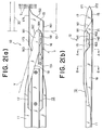
- Figs. 2(a) and 2(b) in which Fig. 2(a) is a top plan view showing the weft feeding rapier head 12 and Fig. 2(b) is a side elevational view of the same.
- the weft feeding rapier head 12 is generally comprised of a guide frame 13 and a gripping mechanism 14 which is secured to the guide frame 13.
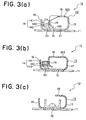
- Figs. 3(a) and 3(b) in which Fig. 3(a) is a front end view of the weft feeding rapier head 12 and Fig. 3(b) is a sectional view of the same taken along a line A-A shown in Fig.
- the gripping mechanism 14 includes a stationary gripping member 141, a movable gripping member 142 which is resiliently deformable or flexible and a leaf spring 143 for resiliently urging the movable gripping member 142 onto the stationary gripping member 141.
- the stationary gripping member 141, the movable gripping member 142 and the leaf spring 143 are fixedly stacked together in this order as viewed from the top, whereby a unitary assembly is formed, which is secured to the guide frame 13 by the screws.
- the guide frame 13 is constituted by a bottom wall 15, a vertically upstanding wall 16 disposed erectly at one lateral side of the bottom wall 15 (i.e., at the side facing a cloth fell of a woven fabric), a sidewall 17 disposed erectly at the other side of the bottom wall 15 (i.e., at the side of a reed 20 on a sley 10), a top wall 18 extending continuously from the side wall 17 and disposed in opposition to the side wall 17 and a vertically suspended wall 19 extending vertically downwardly from the top wall 18.
- Fig. 3(c) which shows the weft feeding rapier head in a sectional view taken along a line B-B in Fig.
- the rapier band 11 is secured to a base portion of the bottom wall 15 by means of screws.
- a mount base 151 mounted fixedly on the upper surface of the bottom wall 15 is a mount base 151 on which a gripping mechanism 14 is secured by means of screws.
- a flat surface forming plate 21 is secured to the lower surface of the bottom wall 15.
- the lower surface of the flat surface forming plate 21 lies flush with that of the rapier band 11, whereby there can be ensured smoothness in guiding a warp on and along the lower surface of the bottom wall 15 (see Fig. 3(a)).
- the flat surface forming plate 21 can be made of synthetic resin materials or metal materials.
- the vertically upstanding wall 16 has an upper edge which is formed continuously by a weft guiding edge portion 161 extending slantly upwardly from the leading end portion of the vertically upstanding wall 16, a weft guiding edge portion 162 extending obliquely downward from the weft guiding edge portion 161 and a weft guiding edge portion 163 extending substantially horizontal.
- the upwardly sloped weft guiding edge portion 161 is also destined to serve as a weft guiding edge portion.
- a weft guiding edge portion 191 is formed at the lower end of the vertically suspended wall 19. More specifically, the weft guiding edge portion 191 is bent or curved toward the side wall 17 from the lower edge of the vertically suspended wall 19. With the arrangement described above, the weft Y can be guided into a gripping portion defined between the stationary gripping member 141 and the movable gripping member 142 through cooperation of the weft guiding edge portions 161, 162, 163 and 191.
- warp guiding edge portions 171 and 172 Formed in upper and lower edge portions of the side wall 17 at locations closer to the leading end thereof are warp guiding edge portions 171 and 172 which are gradually distanced from each other in the direction as viewed from the tip end of the side wall 17.
- the side wall 17 serves as a guide for grouping the warps T into upper and lower warp layers (T) along the warp guiding edge portions 171 and 172 upon operation for forming the shedding.
- the warp guiding action of the warp guiding edge portion 172 is succeeded by a front edge portion 152 of the bottom wall 15 and the bottom surface of the flat surface forming plate 21.
- a slanted warp guiding surface 181 Formed in a tip end portion of the top wall 18 are a slanted warp guiding surface 181 and a forefront edge 184.
- the warp guiding action performed by the warp guiding edge portion 171 is smoothly transferred to the warp guiding action of the warp guiding surface 181.
- a concave-shaped weft guiding edge portion 173 which cooperates with the weft guiding edge portions 161 and 191 to guide the weft Y into the gripping portion of the gripping mechanism 14.
- a weft position regulating recess 183 which serves as a means for regulating the position of the weft. The weft Y which is in the state gripped by the gripping mechanism 14 can thus be brought into contact with the weft position regulating recess 183. In this way, the path of the weft Y which is in the state held by the gripping mechanism 14 is regulated by the weft position regulating recess 183.
- the guide frame 13 is formed by bending correspondingly a single metal sheet (i.e., one and the same metal sheet) so that there are formed in continuation to one another the weft guiding edge portion 161 of the vertically upstanding wall 16, the front edge portion 152 of the bottom wall 15, the warp guiding edge portions 172 and 171 of the side wall 17, the weft guiding edge portion 173 of the side wall 17, the front edge portion 182 of the top wall 18 and the weft guiding edge portion 191 of the vertically suspended wall 19.
- the warp T is guided upwardly at a location of the forefront edge 184, being regulated by the weft guiding edge portion 161 and the warp guiding edge portion 171, to reach the warp guiding surface 181.
- the weft Y is guided downwardly at a location of the forefront edge 184 under regulation by the weft guiding edge portion 161 and the weft guiding edge portion 173 to reach the weft guiding edge portion 191.
- the forefront edge 184 plays a role as a branching point for setting separately the directions in which the warps T and the weft Y are to be guided, respectively.
- the weft feeding rapier head 12 which is gripping and carrying the weft Y encounters a receiving rapier head (not shown) substantially at a central position as viewed in the width direction of the woven fabric, whereby the weft Y gripped by the weft feeding rapier head 12 is transferred to the weft receiving rapier head arrived at a transfer position between the side wall 17 and the vertically suspended wall 19.
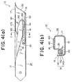
- a vertically suspended wall 25 and a top wall 26 are formed integrally with each other as a unitary structure separately from the other guide frame forming portions.
- the vertically suspended wall 25 and the top wall 26 are formed by bending correspondingly a metal sheet, wherein the top wall 26 is secured to a mounting member 185 formed integrally with the side wall 17.
- the top wall 26 and the vertically suspended wall 25 may also be formed through a precision steel casting process typified by a lost-wax process, a sintering process, an injection molding process, a powder-metallurgical process such as an injection molding/sintering process or the like.
- a vertically upstanding wall 28 is formed separately by bending a metal sheet.
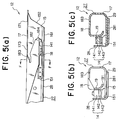
- a spacer 29 Secured to the lower surface of the bottom wall 15 is a spacer 29 having a bottom surface on which the vertically upstanding wall 28 is secured by means of a mounting member 281.
- the metal sheet forming the vertically upstanding wall 28 has a same thickness as that of the metal sheet which forms the bottom wall 15.
- the rapier band 11 secured to the lower surface of the bottom wall 15 has a thickness slightly greater than that of the metal sheet mentioned above.
- the spacer 29 is imparted with a thickness which is dimensioned to be equal to a difference in thickness between the bottom wall 15 and the mounting member 281.
- the lower surface of the mounting member 281 can be flush with the lower surface of the rapier band 11.
- provision of the spacer 29 is required when the overall thickness of the bottom wall 15 and the mounting member 281 is smaller than that of the rapier band 11.
- a vertically upstanding wall 22 is formed separately through a precision steel casting process typified by a lost-wax process, a powder-metallurgical process such as a sintering process, an injection molding process, an injection molding/sintering process or the like.
- the vertically upstanding wall 22 is secured to the upper surface of the bottom wall 15 by means of a mounting member 221.
- a mount base 222 Formed integrally on the upper surface of the mounting member 221 is a mount base 222 on which the gripping mechanism 14 is mounted.
- a vertically upstanding wall 31 is formed separately through a precision steel casting process typified by a lost-wax process, a powder-metallurgical process such as a sintering process, an injection molding process, an injection molding/sintering process or the like.
- a mounting member 311 of the vertically upstanding wall 31 is secured on the lower surface of the bottom wall 15.
- the mounting member 311 has a same thickness as that of the rapier band 11 which is thicker than the vertically upstanding wall 31, wherein the lower surface of the mounting member 311 lies flush with the lower surface of the rapier band 11.
- Formed integrally on the upper surface of the mounting member 311 of the vertically upstanding wall 31 is a mount base 151 on which the gripping mechanism 14 is mounted.
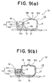
- a protruding portion 186 is formed integrally with the top wall 18 so that the former projects upwardly. More specifically, the protruding portion 186 extends in the longitudinal direction of the weft feeding rapier head 12 so as to cover the weft position regulating recess 183 as viewed in the width direction of the rapier band 11.
- the front end portion of the top wall 18 is likely to be deformed because the weft position regulating recess 183 is formed in the top wall 18.
- the protruding portion 186 is provided as a reinforcing means for preventing such deformation of the top wall 18.
- the protruding portion 186 can be formed by resorting to a drawing process when the top wall 18 is formed by bending a metal sheet. On the other hand, when the top wall 18 is formed through a precision steel casting or a powder-metallurgical process, the protruding portion 186 can be easily formed integrally with the top wall 18 in a unitary cast structure.
- a protruding portion 187 is formed integrally with the top wall 18 so that the former projects downwardly. More specifically, the protruding portion 187 extends in the longitudinal direction of the weft feeding rapier head 12 so as to cover the weft position regulating recess 183 as viewed in the width direction of the rapier band 11.
- the protruding portion 187 is provided as a reinforcing portion for preventing such deformation of the top wall 18, similarly to the protruding portion 186 provided in the rapier head according to the sixth embodiment of the invention.
- the protruding portion 187 can be formed by resorting to a drawing process when the top wall 18 is formed by bending a metal sheet. On the other hand, when the top wall 18 is formed through a precision steel casting or a powder-metallurgical process, the protruding portion 187 can easily be formed integrally with the top wall 18 in a unitary cast structure.
- the warp guiding edge portion formed in the side wall of the guide frame and the weft guiding edge portion formed in the vertically sustained wall are connected together by way of the front edge portion of the top wall.
- the weft guiding edge portion is implemented integrally with lower edge of the vertically suspended wall connected to the top wall of the rapier head, there arises no need for providing the yarn deflecting fin in association with the weft gripping mechanism, differing from the conventional rapier head.
- the gripping mechanism of a simple geometry known per se can be used intactly.
- the positional relationship among the forefront edge, the weft guiding edge portion and the warp guiding edge portion can remain unaltered, the mounting position of the gripping mechanism can be freely changed. In other words, the gripping mechanism can be installed at a position where the weft can be gripped most stably.
Landscapes
- Engineering & Computer Science (AREA)
- Textile Engineering (AREA)
- Looms (AREA)
Applications Claiming Priority (2)
| Application Number | Priority Date | Filing Date | Title |
|---|---|---|---|
| JP9186736A JPH1136159A (ja) | 1997-07-11 | 1997-07-11 | レピア織機における緯入れ装置 |
| JP186736/97 | 1997-07-11 |
Publications (1)
| Publication Number | Publication Date |
|---|---|
| EP0893524A1 true EP0893524A1 (fr) | 1999-01-27 |
Family
ID=16193758
Family Applications (1)
| Application Number | Title | Priority Date | Filing Date |
|---|---|---|---|
| EP98112299A Withdrawn EP0893524A1 (fr) | 1997-07-11 | 1998-07-02 | Organe d'insertion de trame pour métier à tisser à pinces |
Country Status (3)
| Country | Link |
|---|---|
| EP (1) | EP0893524A1 (fr) |
| JP (1) | JPH1136159A (fr) |
| KR (1) | KR19990013464A (fr) |
Cited By (6)
| Publication number | Priority date | Publication date | Assignee | Title |
|---|---|---|---|---|
| WO2001079596A1 (fr) * | 2000-04-17 | 2001-10-25 | Picanol N.V. | Boitier de rapiere pour rapiere de metier a tisser |
| EP1749912A1 (fr) * | 2005-08-05 | 2007-02-07 | Smit S.p.A. - Unipersonale | Tête de ruban pour métier à tisser à griffes et procédé pour sa réalisation |
| CN105220318A (zh) * | 2015-11-19 | 2016-01-06 | 长乐力天针纺有限公司 | 一种纺织剑头送纬剑夹持装置 |
| CN105658856A (zh) * | 2013-10-24 | 2016-06-08 | 米歇尔.范德威尔公司 | 送纬剑杆头、送纬剑杆、剑杆式织机、及使用这种送纬剑杆头在这种剑杆式织机中引入纬纱的方法 |
| CN107587243A (zh) * | 2017-10-13 | 2018-01-16 | 浙江巨剑纺织机械有限公司 | 一种适应用于多种纱线的剑杆织机送纬剑头 |
| CN113293485A (zh) * | 2021-05-26 | 2021-08-24 | 绍兴市嘉纬电子科技有限公司 | 一种高速耐磨型纺织剑头 |
Families Citing this family (2)
| Publication number | Priority date | Publication date | Assignee | Title |
|---|---|---|---|---|
| KR100351416B1 (ko) * | 1999-07-07 | 2002-09-09 | 대흥정밀공업 주식회사 | 레피어직기용 그리퍼헤드 |
| KR100949722B1 (ko) * | 2002-08-12 | 2010-03-25 | 에이펙셀 (주) | 마이크로 초미립 분쇄기 |
Citations (7)
| Publication number | Priority date | Publication date | Assignee | Title |
|---|---|---|---|---|
| FR2222467A1 (fr) * | 1973-03-22 | 1974-10-18 | Rockwell International Corp | |
| US4071055A (en) * | 1975-09-29 | 1978-01-31 | Ruti Machinery Works Ltd. | Inserting carrier for looms with removal of a filling yarn from stationary bobbins |
| GB2018307A (en) * | 1978-04-07 | 1979-10-17 | Somet Soc Mec Tessile | A weft-inserting gripper for a continuous weft feed loom |
| JPH0214439A (ja) * | 1988-06-30 | 1990-01-18 | Toshiba Corp | 焦点制御装置 |
| EP0441099A1 (fr) * | 1990-02-05 | 1991-08-14 | Sulzer RàTi Ag | Griffe porteuse pour métiers à tisser à griffes |
| EP0624671A1 (fr) * | 1993-05-12 | 1994-11-17 | Sulzer RàTi Ag | Dispositif de retenue d'un fil pour une griffe d'amenée et métier à tisser à griffer avec un dispositif de retenue d'un fil |
| EP0792961A1 (fr) * | 1996-02-27 | 1997-09-03 | NUOVO PIGNONE S.p.A. | Pince d'amenée et métier à tisser à pinces |
-
1997
- 1997-07-11 JP JP9186736A patent/JPH1136159A/ja active Pending
-
1998
- 1998-06-29 KR KR1019980024763A patent/KR19990013464A/ko not_active Ceased
- 1998-07-02 EP EP98112299A patent/EP0893524A1/fr not_active Withdrawn
Patent Citations (7)
| Publication number | Priority date | Publication date | Assignee | Title |
|---|---|---|---|---|
| FR2222467A1 (fr) * | 1973-03-22 | 1974-10-18 | Rockwell International Corp | |
| US4071055A (en) * | 1975-09-29 | 1978-01-31 | Ruti Machinery Works Ltd. | Inserting carrier for looms with removal of a filling yarn from stationary bobbins |
| GB2018307A (en) * | 1978-04-07 | 1979-10-17 | Somet Soc Mec Tessile | A weft-inserting gripper for a continuous weft feed loom |
| JPH0214439A (ja) * | 1988-06-30 | 1990-01-18 | Toshiba Corp | 焦点制御装置 |
| EP0441099A1 (fr) * | 1990-02-05 | 1991-08-14 | Sulzer RàTi Ag | Griffe porteuse pour métiers à tisser à griffes |
| EP0624671A1 (fr) * | 1993-05-12 | 1994-11-17 | Sulzer RàTi Ag | Dispositif de retenue d'un fil pour une griffe d'amenée et métier à tisser à griffer avec un dispositif de retenue d'un fil |
| EP0792961A1 (fr) * | 1996-02-27 | 1997-09-03 | NUOVO PIGNONE S.p.A. | Pince d'amenée et métier à tisser à pinces |
Cited By (8)
| Publication number | Priority date | Publication date | Assignee | Title |
|---|---|---|---|---|
| WO2001079596A1 (fr) * | 2000-04-17 | 2001-10-25 | Picanol N.V. | Boitier de rapiere pour rapiere de metier a tisser |
| US6923220B2 (en) | 2000-04-17 | 2005-08-02 | Picanol N.V. | Gripper housing |
| EP1749912A1 (fr) * | 2005-08-05 | 2007-02-07 | Smit S.p.A. - Unipersonale | Tête de ruban pour métier à tisser à griffes et procédé pour sa réalisation |
| CN105658856A (zh) * | 2013-10-24 | 2016-06-08 | 米歇尔.范德威尔公司 | 送纬剑杆头、送纬剑杆、剑杆式织机、及使用这种送纬剑杆头在这种剑杆式织机中引入纬纱的方法 |
| CN105220318A (zh) * | 2015-11-19 | 2016-01-06 | 长乐力天针纺有限公司 | 一种纺织剑头送纬剑夹持装置 |
| CN105220318B (zh) * | 2015-11-19 | 2018-01-05 | 长乐力天针纺有限公司 | 一种纺织剑头送纬剑夹持装置 |
| CN107587243A (zh) * | 2017-10-13 | 2018-01-16 | 浙江巨剑纺织机械有限公司 | 一种适应用于多种纱线的剑杆织机送纬剑头 |
| CN113293485A (zh) * | 2021-05-26 | 2021-08-24 | 绍兴市嘉纬电子科技有限公司 | 一种高速耐磨型纺织剑头 |
Also Published As
| Publication number | Publication date |
|---|---|
| KR19990013464A (ko) | 1999-02-25 |
| JPH1136159A (ja) | 1999-02-09 |
Similar Documents
| Publication | Publication Date | Title |
|---|---|---|
| EP0893524A1 (fr) | Organe d'insertion de trame pour métier à tisser à pinces | |
| JPH0713337B2 (ja) | 織機の杼口内における横糸支持グリッパの運動案内装置 | |
| US4638839A (en) | Guide for the gripper carrying straps inside the shed of weaving looms | |
| CN1705778B (zh) | 片梭织机的给料片梭 | |
| US5129431A (en) | Giver for a gripper loom | |
| EP1209267B1 (fr) | Dispositif d'insertion de la trame pour métier à tisser à griffes | |
| JP3796268B2 (ja) | グリッパ式織機 | |
| US4062382A (en) | Extending carrier for looms with removal of the filling yarn from stationary bobbins | |
| WO1994010364A2 (fr) | Systeme de transfert pour metiers a tisser | |
| US5819812A (en) | Giver gripper for a gripper loom | |
| EP0715009B1 (fr) | Moyen pour guider le mouvement d'une paire de griffes lelong de la foule de métiers à tisser | |
| US5135033A (en) | Rapier loom having picking tapes and spacers | |
| KR930000371B1 (ko) | 북 없는 직기의 위사 반송 그리퍼 쌍 | |
| GB2058853A (en) | Weft inserting device for shuttleless loom | |
| US5615714A (en) | Guide system for the gripper insertion tape in a shuttleless loom | |
| JP2002146648A (ja) | レピア織機における緯入れ装置 | |
| KR100330283B1 (ko) | 위사반송그리퍼 | |
| EP0905296A1 (fr) | Dispositif d'insertion de la trame pour métiers à tisser à griffes | |
| US4505305A (en) | Carrying gripper for looms | |
| JP2001348759A (ja) | レピア織機の緯入れ装置 | |
| KR200217138Y1 (ko) | 위사인출그리퍼 | |
| KR880001264B1 (ko) | 북없는 직조기의 위사운반체 | |
| BE1013013A3 (nl) | Grijperband voor een grijperweefmachine. | |
| JPH10204749A (ja) | レピア織機における緯入機構 | |
| JP2000234241A (ja) | レピア織機におけるレピアヘッド |
Legal Events
| Date | Code | Title | Description |
|---|---|---|---|
| PUAI | Public reference made under article 153(3) epc to a published international application that has entered the european phase |
Free format text: ORIGINAL CODE: 0009012 |
|
| 17P | Request for examination filed |
Effective date: 19980702 |
|
| AK | Designated contracting states |
Kind code of ref document: A1 Designated state(s): BE CH IT LI |
|
| AX | Request for extension of the european patent |
Free format text: AL;LT;LV;MK;RO;SI |
|
| AKX | Designation fees paid |
Free format text: BE CH IT LI |
|
| REG | Reference to a national code |
Ref country code: DE Ref legal event code: 8566 |
|
| STAA | Information on the status of an ep patent application or granted ep patent |
Free format text: STATUS: THE APPLICATION HAS BEEN WITHDRAWN |
|
| 18W | Application withdrawn |
Withdrawal date: 20000111 |