EP0893614A2 - Appareil de transmission de puissance - Google Patents
Appareil de transmission de puissance Download PDFInfo
- Publication number
- EP0893614A2 EP0893614A2 EP98114815A EP98114815A EP0893614A2 EP 0893614 A2 EP0893614 A2 EP 0893614A2 EP 98114815 A EP98114815 A EP 98114815A EP 98114815 A EP98114815 A EP 98114815A EP 0893614 A2 EP0893614 A2 EP 0893614A2
- Authority
- EP
- European Patent Office
- Prior art keywords
- working oil
- clutch
- rolling bearing
- outer ring
- bearing clutch
- Prior art date
- Legal status (The legal status is an assumption and is not a legal conclusion. Google has not performed a legal analysis and makes no representation as to the accuracy of the status listed.)
- Granted
Links
Images


Classifications
-
- F—MECHANICAL ENGINEERING; LIGHTING; HEATING; WEAPONS; BLASTING
- F16—ENGINEERING ELEMENTS AND UNITS; GENERAL MEASURES FOR PRODUCING AND MAINTAINING EFFECTIVE FUNCTIONING OF MACHINES OR INSTALLATIONS; THERMAL INSULATION IN GENERAL
- F16D—COUPLINGS FOR TRANSMITTING ROTATION; CLUTCHES; BRAKES
- F16D41/00—Freewheels or freewheel clutches
- F16D41/06—Freewheels or freewheel clutches with intermediate wedging coupling members between an inner and an outer surface
- F16D41/061—Freewheels or freewheel clutches with intermediate wedging coupling members between an inner and an outer surface the intermediate members wedging by movement having an axial component
-
- F—MECHANICAL ENGINEERING; LIGHTING; HEATING; WEAPONS; BLASTING
- F16—ENGINEERING ELEMENTS AND UNITS; GENERAL MEASURES FOR PRODUCING AND MAINTAINING EFFECTIVE FUNCTIONING OF MACHINES OR INSTALLATIONS; THERMAL INSULATION IN GENERAL
- F16D—COUPLINGS FOR TRANSMITTING ROTATION; CLUTCHES; BRAKES
- F16D41/00—Freewheels or freewheel clutches
- F16D41/06—Freewheels or freewheel clutches with intermediate wedging coupling members between an inner and an outer surface
- F16D41/08—Freewheels or freewheel clutches with intermediate wedging coupling members between an inner and an outer surface with provision for altering the freewheeling action
- F16D41/086—Freewheels or freewheel clutches with intermediate wedging coupling members between an inner and an outer surface with provision for altering the freewheeling action the intermediate members being of circular cross-section and wedging by rolling
-
- F—MECHANICAL ENGINEERING; LIGHTING; HEATING; WEAPONS; BLASTING
- F16—ENGINEERING ELEMENTS AND UNITS; GENERAL MEASURES FOR PRODUCING AND MAINTAINING EFFECTIVE FUNCTIONING OF MACHINES OR INSTALLATIONS; THERMAL INSULATION IN GENERAL
- F16H—GEARING
- F16H45/00—Combinations of fluid gearings for conveying rotary motion with couplings or clutches
- F16H45/02—Combinations of fluid gearings for conveying rotary motion with couplings or clutches with mechanical clutches for bridging a fluid gearing of the hydrokinetic type
-
- F—MECHANICAL ENGINEERING; LIGHTING; HEATING; WEAPONS; BLASTING
- F16—ENGINEERING ELEMENTS AND UNITS; GENERAL MEASURES FOR PRODUCING AND MAINTAINING EFFECTIVE FUNCTIONING OF MACHINES OR INSTALLATIONS; THERMAL INSULATION IN GENERAL
- F16H—GEARING
- F16H41/00—Rotary fluid gearing of the hydrokinetic type
- F16H41/24—Details
- F16H2041/246—Details relating to one way clutch of the stator
Definitions
- the present invention relates to a power transmitting apparatus according to the preamble of patent claim 1.
- the power transmitting apparatus such as a fluid coupling, a torque converter or the like for transmitting power from a driving side to a driven side using fluid joint means, of the present invention can mechanically connect a driving side to a driven side with a clutch mechanism interposed therebetween and assures that a power transmitting efficiency can be improved, without any slip loss, by equalizing the rotational speed of input from a prime mover to the rotational speed of a unit to be driven.
- a power transmitting apparatus such as a fluid coupling, a torque converter or the like, for transmitting power from a driving shaft to a driven shaft via fluid filled in a casing where a pump impeller is connected to a driving shaft and a turbine impeller is connected to a driven shaft, is known.
- the Document DE-A-3144194 describes a hydraulic torque converter for motor vehicles for transmitting the engine torque to a driven wheel by means of a hydraulic fluid and/or a mechanical overrunning clutch.
- the mechanical clutch has an annular driving clutch member with a conical track on the inner periphery and a driven clutch member with a conical track on the outer periphery, the two tracks being parallel to and facing each other.
- a roller cage supporting a plurality of shock-absorbing, tapered, cylindrical rollers of a resilient material is arranged between the two tracks. When the clutch is not in operation, each roller is at a predetermined angle of inclination to the generatrix of a conical surface having the same angle as the conical tracks and passing through the middle of the roller.
- the driven clutch member is connected to a piston which is slidingly seated in a hydraulic chamber and urged in a direction away from the driving clutch member by the force of a spring.
- the introduction of hydraulic fluid into the chamber causes the piston to urge the driven clutch member close to the driving clutch member against the force of the spring, bringing the rollers into pressure contact with the track surfaces.
- the maximum rotational speed of the driven shaft is lower than that of the driving shaft or an input rotational speed of the prime mover such as a motor or an engine usually by about 3 % owing to slippage.
- This slippage can not be avoided when the rotational speed is controlled by a fluid coupling. Therefore, the fluid coupling efficiency is reduced owing to slippage by a quantity corresponding to the slip percentage and the larger the transmitting power, the larger the loss of power.
- the present invention was made to overcome the aforementioned problems and its object resides in providing a power transmitting apparatus which includes a clutch mechanism for mechanically connecting the driving side to the driven side and which assures that slip loss is eliminated by equalizing the rotational speed of input from a prime mover to the rotational speed of a unit to be driven, resulting in an improved power transmitting efficiency.
- the present invention provides a power transmitting apparatus for transmitting power from a driving side to a driven side using fluid joint means, wherein a rolling bearing clutch including an inner ring, an outer ring and a plurality of rollers interposed between the outer periphery of the inner ring and the inner periphery of the outer ring is disposed between the driving side and the driven side, the rolling bearing clutch being ON/OFF operated by allowing the track surfaces of the inner ring and the outer ring to move close to each other or away from each other, whereby the driving side and the driven side can be mechanically connected to each other not via fluid joint means by shifting the rolling bearing clutch to the ON position.
- a rolling bearing clutch including an inner ring, an outer ring and a plurality of rollers interposed between the outer periphery of the inner ring and the inner periphery of the outer ring is disposed between the driving side and the driven side, the rolling bearing clutch being ON/OFF operated by allowing the track surfaces of the inner ring and the outer ring to move close to
- the rolling bearing clutch may be constructed in such a way that the inner and outer rings are locked by imparting a thrust force to the inner or outer ring with the thrusting means while the inner and outer rings are relatively rotated in the rolling direction opposite to the locking direction, whereby the rolling bearing clutch is held in the ON position.
- the inner and outer rings are freely rotatable by releasing the thrusting means from the thrust position, whereby the rolling bearing clutch is held in the OFF position.
- a power transmitting apparatus such as a fluid coupling, a torque converter or the like for transmitting power from a driving side to a driven side makes it possible to mechanically connect the driving side to the driven side not via fluid joint means because the rolling bearing clutch is disposed between the driving side and the driven side.
- slip loss of the fluid joint means can be eliminated by equalizing the rotational speed of input from the prime mover to the rotational speed of a unit to be driven, resulting in improved power transmitting efficiency.
- the thrusting means When the rolling bearing clutch is shifted to the ON position, the thrusting means may be driven by utilizing the centrifugal pressure of a fluid to displace the outer ring, whereby the track surfaces of the inner ring and the outer ring come close to each other. It should be noted that since the rolling bearing clutch is designed such that the track surfaces of the inner ring and the outer ring are moved away from each other when the thrusting force is released, the mechanical coupling between the driving side and the driven side can be immediately disconnected.
- Fig. 1 is a sectional view which shows the entire structure of the fluid coupling.
- reference numeral 1 denotes a driving shaft, and driven shaft 4 is arranged adjacent to the driving shaft 1.
- the driving shaft 1 is rotatably supported in a bearing metal sleeve 13 disposed in a bearing casing 18, whereas the driven shaft 4 is rotatably supported in bearing metal sleeves 15, 16 disposed in a bearing casing 19.
- the bearing casings 18 and 19 are held in position by a bearing casing retainer 20.
- An impeller 2 is connected to the driving shaft 1, and a runner 3 is connected to the driven shaft 4.
- An impeller casing 5 is fixed to the impeller 2, and an outer annulus 24 is fixed to the impeller casing 5.
- An outer sleeve 25 is attached to the outer annulus 24, and an inner annulus 6 is attached to the outer sleeve 25.
- a rolling bearing clutch C L is disposed in the space surrounded by the impeller casing 5, the outer annulus 24 and the inner annulus 6.
- a ball spline mechanism 26 allows the axial relative movement between the outer ring 9 and the outer sleeve 25 while preventing relative rotational movement therebetween.
- a space surrounded by the outer sleeve 25 and the inner annulus 6 constitutes a cylinder portion, and a piston 7 is axially displaceably disposed in the cylinder portion.
- a clutch ON/OFF working oil chamber 30 is defined between the inner surface of the cylinder portion and the piston 7 so that working oil is fed to the working oil chamber 30 via working oil feeding passages 31a, 31b, 31c and 31d, each formed in the bearing casing 19 and the inner annulus 6.
- the working oil feeding passage 31a is hydraulically connected via a pipe to a hydraulic pump (as will be described later).
- a plurality of balls 23 are interposed between the piston 7 and the outer ring 9 which allow the relative rotational movement therebetween.
- a radial bearing 32 is interposed between the outer annulus 24 and the inner ring 8.
- the thrust force of the driving shaft 1 is borne by a thrust bearing 14, and the thrust force of the driven shaft 4 is borne by a thrust bearing 17.
- a plurality of nozzles 21 are disposed along the outer periphery of the impeller casing 5.
- a working oil chamber of the fluid coupling impeller is constituted by the impeller 2, the runner 3 and the impeller casing 5.
- the working oil is fed to the fluid coupling impeller working oil chamber via a working oil feeding passage 18a of the bearing casing 18 and an oil feeding hole 2a of the impeller 2.
- the passage for feeding the working oil to the fluid coupling impeller working oil chamber comprises a passage I 1 which includes an opening/closing control valve f 1 adapted to quickly perform full opening and full closing and a maximum oil flow rate adjusting orifice j, and a passage I 2 which includes an opening/closing control valve f 2 disposed in parallel with the control valve f 1 to bypass the latter and a minimum oil flow rate adjusting orifice h.
- the working oil is fed to the working oil chamber from an oil tank a via a strainer b through the passage I 1 or I 2 , the oil feeding passage 18a of the bearing casing 18 on the driving side and the oil feeding hole 2a of the impeller 2.
- the working oil in the working oil chamber is discharged to the outside via the nozzles 21.
- a hydraulic pressure adjusting relief valve d and an oil cooler e are arranged.
- a flow rate of working oil fed to the working oil chamber is determined by the maximum oil flow rate adjusting orifice j when the control valve f 1 is fully opened, and a minimum flow rate is determined by the minimum oil flow rate adjusting orifice h when the control valve f 1 is fully closed and the control valve f 2 is fully opened.
- the rotational speed of the unit is driven at a maximum rotational speed when the control valve f 1 is fully opened, and it is driven at a minimum rotational speed when the control valve f 1 is fully closed and the control valve f 2 is fully opened.
- the feeding of the working oil to the clutch ON/OFF working oil chamber 30 is achieved by the oil pump c through a passage I 3 , a control valve k and communication passages 31a to 31d (see Fig. 1).
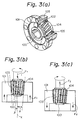
- the structure as shown in Fig. 3 is known as a rolling bearing clutch.
- the rolling bearing clutch includes an inner ring 100, an outer ring 101 and a number of rollers 104 interposed between the outer periphery of the inner ring 100 and the inner periphery of the outer ring 101 as shown in Fig. 3(a).
- the rollers 104 are arranged with a predetermined twist angle ⁇ relative to a center axis X of the inner and outer rings 100 and 101 as shown in Fig. 3(b).
- a track surface 102 of the outer periphery of the inner ring 100 is convergent in the form of a substantially circular conical taper surface, and a track surface 103 of the inner periphery of the outer ring 101 is designed also in the form of a substantially circular conical taper surface corresponding to the track surface 102 of the inner ring 100. More precisely, since the track surfaces 102 and 103 are under a condition that the rollers 104 come into line contact with them, they respectively assume a single hyperboloid contour that is a locus which is scribed by turning the rollers 104 about the center axis X. The track surfaces 102 and 103 of the inner and outer rings 100 and 101 are inclined at a predetermined socket angle ⁇ relative to the center axis X.
- the rollers 104 come into contact with the track surfaces 102 and 103 of the inner and outer rings 100 and 101 with a predetermined twist angle ⁇ so that as the inner and outer rings 100 and 101 are rotated, the rollers 104 spirally roll between the inner and outer rings 100 and 101.
- a clutch component F1 which serves to allow the inner ring 100 and the outer ring 101 to move near to each other in the axial direction due to the rolling of the rollers 104 appears so that the rollers 104 between the inner ring 100 and the outer ring 101 are brought into a locked position, enabling torque to be transmitted.
- the known rolling bearing clutch explained above is utilized as a one-way clutch which transmits torque in one direction and freely rotates in the other direction by utilizing the aforementioned characteristics.
- a plurality of preliminary pressure springs 105 for imparting light preliminary pressure between the inner ring 100 and the outer ring 101 are arranged between the inner ring 100 and the outer ring 101 so as to allow the rollers 104 to come into initial contact with the inner and outer rings 100 and 101.
- a centrifugal force Px in the working oil in the chamber 30 for actuating the rolling bearing clutch C L is represented by the following formula.
- ⁇ denotes a specific weight of the working oil
- ⁇ denotes a rotational angular speed
- the rolling bearing clutch C L is constructed such that the clutch is shifted to the ON position by imparting a thrust force to the outer ring by thrusting means while the inner and outer rings are relatively rotated in the opposite rolling direction to the locking direction, and it is used as a one-way clutch.
- the structure of the track surfaces of the inner and outer rings is entirely the same as the conventional one but in contrast thereto, an untwisting operation is not required. That is, in the conventional rolling bearing clutch, since the rollers squeeze between the inner and outer rings in the clutch ON position, an untwisting operation is necessary to shift the clutch from the clutch ON position to the clutch OFF position.
- the rolling bearing clutch C L includes an inner ring 58, an outer ring 59, a plurality of cylindrical rollers 60, and a retainer 62 for holding the rollers 60 at predetermined positions.
- the inner ring 58 is connected directly to the runner 3.
- the outer ring 59 is connected to the outer sleeve 25 via the ball spline mechanism 26, and the outer ring 59 is displaceable relative to the outer sleeve 25 in the axial direction while it is rotated together with the outer sleeve 25.
- the outer annulus 24 is fixed to the impeller casing 5.
- a plurality of preliminary pressure springs 61 are interposed between the opposing surfaces of the outer ring 59 and the outer sleeve 25 so that the outer ring 59 is thrust to the inner ring 58 in the axial direction so as to impart preliminary pressure to each roller 60.
- the structure of track surfaces 58a and 59a of the inner ring 58 and the outer ring 59 is entirely the same as that of the conventional ones having a hyperboloid contour and description of the structure of the track surface is herein omitted.
- the driving shaft 1 is relatively rotated only in the rolling direction opposite to the locking direction of the inner and outer rings of the rolling bearing clutch C L . then the rolling bearing clutch C L is held in the OFF position, even though the driving shaft 1 is rotated, the outer ring 59 is rotated together with the outer annulus 24.
- the rollers 60 roll, since a rolling component effective for parting the inner and outer rings 58 and 59 away from each other is caused, the rollers 60 are rotated freely without causing any rotation of the inner ring 58.
- the control valve k is opened while the foregoing position is maintained, the working oil is fed to the working oil chamber 30 so that the pressure is caused in the working oil in the working oil chamber 30 by the centrifugal force.
- the piston 7 is thus thrust in the leftward direction by the pressure and the track surfaces of the outer ring 59 and the inner ring 58 come near to each other, causing the rolling bearing clutch C L to be shifted to the ON position so that the driving shaft 1 and the shaft 4 of a unit to be driven are mechanically coupled to each other.
- the working oil in the working oil chamber 30 is discharged from the nozzles 28 by the centrifugal force so that the piston 7 is released from the thrusting force.
- the rollers 60 roll, a component effective for parting the inner and outer rings 58 and 59 away from each other appears, causing the rollers 60 to be rotated freely, whereby the rolling bearing clutch C L is immediately shifted to the OFF position.
- Figs. 1 and 2 an example where the power transmitting apparatus of the present invention is applied to the fluid coupling is shown.
- the present invention should not be limited only to a fluid coupling but it can equally be a torque converter.
- a power transmitting efficiency can be improved without any slip loss by mechanically connecting the driving side to the driven side.
- operation can be performed at a minimum rotational speed at the time of no loading, and operation can be performed at the same rated rotational speed as that of a prime mover without including slip loss at the time of loading. Consequently, a large saving in energy can be obtained by simple control.
Landscapes
- Engineering & Computer Science (AREA)
- General Engineering & Computer Science (AREA)
- Mechanical Engineering (AREA)
- Rolling Contact Bearings (AREA)
- Friction Gearing (AREA)
- Hydraulic Clutches, Magnetic Clutches, Fluid Clutches, And Fluid Joints (AREA)
- Support Of The Bearing (AREA)
Applications Claiming Priority (4)
| Application Number | Priority Date | Filing Date | Title |
|---|---|---|---|
| JP7169215A JPH08338503A (ja) | 1995-06-12 | 1995-06-12 | 動力伝達装置 |
| JP16921595 | 1995-06-12 | ||
| JP169215/95 | 1995-06-12 | ||
| EP96109322A EP0748946B1 (fr) | 1995-06-12 | 1996-06-11 | Appareil de transmission de puissance |
Related Parent Applications (1)
| Application Number | Title | Priority Date | Filing Date |
|---|---|---|---|
| EP96109322A Division EP0748946B1 (fr) | 1995-06-12 | 1996-06-11 | Appareil de transmission de puissance |
Publications (3)
| Publication Number | Publication Date |
|---|---|
| EP0893614A2 true EP0893614A2 (fr) | 1999-01-27 |
| EP0893614A3 EP0893614A3 (fr) | 1999-03-10 |
| EP0893614B1 EP0893614B1 (fr) | 2001-11-14 |
Family
ID=15882352
Family Applications (2)
| Application Number | Title | Priority Date | Filing Date |
|---|---|---|---|
| EP96109322A Expired - Lifetime EP0748946B1 (fr) | 1995-06-12 | 1996-06-11 | Appareil de transmission de puissance |
| EP98114815A Expired - Lifetime EP0893614B1 (fr) | 1995-06-12 | 1996-06-11 | Appareil de transmission de puissance |
Family Applications Before (1)
| Application Number | Title | Priority Date | Filing Date |
|---|---|---|---|
| EP96109322A Expired - Lifetime EP0748946B1 (fr) | 1995-06-12 | 1996-06-11 | Appareil de transmission de puissance |
Country Status (4)
| Country | Link |
|---|---|
| US (1) | US5850897A (fr) |
| EP (2) | EP0748946B1 (fr) |
| JP (1) | JPH08338503A (fr) |
| DE (2) | DE69610527T2 (fr) |
Families Citing this family (8)
| Publication number | Priority date | Publication date | Assignee | Title |
|---|---|---|---|---|
| JP2000186752A (ja) * | 1998-12-22 | 2000-07-04 | Kenji Mimura | 回転摩擦装置 |
| JP3364603B2 (ja) * | 1999-06-25 | 2003-01-08 | 建治 三村 | 摩擦クラッチ及びこれを用いた自動車の自動変速機及び自動車の無段変速機並びに自動車の動力分配装置及び自動二輪車の動力伝達装置 |
| JP2001136878A (ja) * | 1999-11-17 | 2001-05-22 | Ken Matsuura Lacing Service:Kk | 両軸受型リール |
| JP4523105B2 (ja) * | 2000-02-24 | 2010-08-11 | 株式会社ユタカ技研 | トルクコンバータ |
| WO2002046634A2 (fr) * | 2000-12-04 | 2002-06-13 | Ebara Corporation | Coupleur hydraulique |
| CN103122953B (zh) * | 2011-11-21 | 2016-04-27 | 洛阳百思特精密机械制造有限公司 | 内圈带槽可逆楔块式超越离合器 |
| JP5897951B2 (ja) * | 2012-03-28 | 2016-04-06 | 株式会社ユニバンス | クラッチ装置 |
| JP2026510323A (ja) * | 2023-03-02 | 2026-04-02 | テックスピン ベアリングス リミテッド | テーパローラを備えたワンウェイクラッチ |
Citations (1)
| Publication number | Priority date | Publication date | Assignee | Title |
|---|---|---|---|---|
| DE3144194A1 (de) | 1980-11-07 | 1982-07-08 | Honda Giken Kogyo K.K., Tokyo | Hydraulischer drehmomentwandler |
Family Cites Families (20)
| Publication number | Priority date | Publication date | Assignee | Title |
|---|---|---|---|---|
| FR609572A (fr) * | 1925-09-17 | 1926-08-17 | C P Sandberg Et John Charles W | Perfectionnements aux dispositifs d'embrayage |
| US1955879A (en) * | 1930-10-16 | 1934-04-24 | Packard Motor Car Co | Transmission mechanism |
| JPS5121093B1 (fr) * | 1968-03-29 | 1976-06-30 | ||
| JPS513853B2 (fr) * | 1972-06-14 | 1976-02-06 | ||
| JPS5121093A (ja) * | 1974-08-13 | 1976-02-19 | Nippon Cable System Inc | Intaarotsukukiko |
| JPS5852092B2 (ja) * | 1975-03-31 | 1983-11-19 | 信夫 高田 | イツポウクラツチ |
| DE2514738A1 (de) * | 1975-04-04 | 1976-10-14 | Herbert Brockel | Hydro-drehmoment-kupplung |
| JPS5536852A (en) * | 1978-09-07 | 1980-03-14 | Canon Inc | Display device for cine camera |
| JPS5794163A (en) * | 1980-11-29 | 1982-06-11 | Honda Motor Co Ltd | Operation controller for fluid torque convertor of vehicle |
| JPS5943670B2 (ja) * | 1981-11-28 | 1984-10-23 | 本田技研工業株式会社 | クラツチ内蔵型流体トルクコンバ−タ装置 |
| US5067601A (en) * | 1987-10-22 | 1991-11-26 | Castens Rudolf R | Clutches |
| US5035309A (en) * | 1989-05-08 | 1991-07-30 | Nobuo Takada | Rolling-contact bearing type clutch |
| GB2241755B (en) * | 1990-03-08 | 1994-01-12 | Kubota Kk | Conical roller type clutch apparatus |
| JP2938966B2 (ja) * | 1990-11-21 | 1999-08-25 | テイエチケー株式会社 | ころがり軸受クラッチ |
| JP3084078B2 (ja) * | 1991-03-18 | 2000-09-04 | テイエチケー株式会社 | トルク吸収装置 |
| WO1993000520A1 (fr) * | 1991-06-20 | 1993-01-07 | Hybo Science, Inc. | Roue libre amelioree pour reacteur de convertisseur de couple |
| WO1993000519A1 (fr) * | 1991-06-20 | 1993-01-07 | Hybo Science, Inc. | Accouplement de securite pour arbres rotatifs en ligne |
| JPH081224B2 (ja) * | 1991-11-27 | 1996-01-10 | 株式会社テイエチケーメント研究所 | ころがり軸受クラッチ |
| JPH081222B2 (ja) * | 1992-05-14 | 1996-01-10 | 株式会社テイエチケーメント研究所 | 傾斜ころ軸受状構造物 |
| JP2566874B2 (ja) * | 1993-05-17 | 1996-12-25 | 株式会社テイエチケーメント研究所 | 遠心クラッチ |
-
1995
- 1995-06-12 JP JP7169215A patent/JPH08338503A/ja active Pending
-
1996
- 1996-06-11 US US08/661,546 patent/US5850897A/en not_active Expired - Fee Related
- 1996-06-11 EP EP96109322A patent/EP0748946B1/fr not_active Expired - Lifetime
- 1996-06-11 EP EP98114815A patent/EP0893614B1/fr not_active Expired - Lifetime
- 1996-06-11 DE DE69610527T patent/DE69610527T2/de not_active Expired - Fee Related
- 1996-06-11 DE DE69617049T patent/DE69617049T2/de not_active Expired - Fee Related
Patent Citations (1)
| Publication number | Priority date | Publication date | Assignee | Title |
|---|---|---|---|---|
| DE3144194A1 (de) | 1980-11-07 | 1982-07-08 | Honda Giken Kogyo K.K., Tokyo | Hydraulischer drehmomentwandler |
Also Published As
| Publication number | Publication date |
|---|---|
| US5850897A (en) | 1998-12-22 |
| DE69617049D1 (de) | 2001-12-20 |
| EP0893614B1 (fr) | 2001-11-14 |
| DE69610527T2 (de) | 2001-05-17 |
| EP0748946A1 (fr) | 1996-12-18 |
| JPH08338503A (ja) | 1996-12-24 |
| EP0893614A3 (fr) | 1999-03-10 |
| DE69610527D1 (de) | 2000-11-09 |
| DE69617049T2 (de) | 2002-03-21 |
| EP0748946B1 (fr) | 2000-10-04 |
Similar Documents
| Publication | Publication Date | Title |
|---|---|---|
| US4632207A (en) | Mechanism to engage part time drive system in a moving vehicle | |
| EP0893614B1 (fr) | Appareil de transmission de puissance | |
| US5931756A (en) | Metal V-belt type continuously variable transmission | |
| US7717245B2 (en) | Self-actuating clutch | |
| JPS62110061A (ja) | 連続可変ベルト駆動装置 | |
| EP0550972B1 (fr) | Roue libre avec un cage conçue pour la circulation du lubrifiant | |
| EP0900946B1 (fr) | Embrayage/roulement à rouleau | |
| US10113595B2 (en) | Concentric V-groove coupling | |
| US4648492A (en) | Mechanism to engage part time drive system in a moving vehicle | |
| JPH06341500A (ja) | 無段変速装置 | |
| JP2002206606A (ja) | プーリ式無段変速装置 | |
| GB2217404A (en) | Switching mechanism for changing speed in a rolling mill drive | |
| US4435997A (en) | Automatic continuously variable transmission | |
| CN109690135A (zh) | 变速器和设置有这种变速器的车辆 | |
| JP2002505729A (ja) | 流体駆動装置 | |
| US10378621B2 (en) | Continuously variable transmission | |
| CA1121289A (fr) | Accouplement frictionnel a cones concentriques, notamment pour mecanismes de propulsion de bateaux | |
| US8025603B2 (en) | Dual torque path transmission with switchable radially displacing one-way clutch and fluid coupling brake | |
| JPH08338502A (ja) | 動力伝達装置の制御方法 | |
| JP2001173753A (ja) | 動力伝達装置 | |
| JP2001173684A (ja) | 動力伝達装置 | |
| JPH06221400A (ja) | 無段変速機の前後進切換装置 | |
| NO20240502A1 (en) | A tractor for propelling an apparatus inside a cylindrical body | |
| US2490503A (en) | Automatic speed change transmission | |
| JP2004308868A (ja) | トロイダル型無段変速機 |
Legal Events
| Date | Code | Title | Description |
|---|---|---|---|
| PUAI | Public reference made under article 153(3) epc to a published international application that has entered the european phase |
Free format text: ORIGINAL CODE: 0009012 |
|
| PUAL | Search report despatched |
Free format text: ORIGINAL CODE: 0009013 |
|
| AC | Divisional application: reference to earlier application |
Ref document number: 748946 Country of ref document: EP |
|
| AK | Designated contracting states |
Kind code of ref document: A2 Designated state(s): DE GB IT |
|
| AK | Designated contracting states |
Kind code of ref document: A3 Designated state(s): DE GB IT |
|
| 17P | Request for examination filed |
Effective date: 19990722 |
|
| 17Q | First examination report despatched |
Effective date: 19991111 |
|
| GRAG | Despatch of communication of intention to grant |
Free format text: ORIGINAL CODE: EPIDOS AGRA |
|
| GRAG | Despatch of communication of intention to grant |
Free format text: ORIGINAL CODE: EPIDOS AGRA |
|
| GRAH | Despatch of communication of intention to grant a patent |
Free format text: ORIGINAL CODE: EPIDOS IGRA |
|
| GRAH | Despatch of communication of intention to grant a patent |
Free format text: ORIGINAL CODE: EPIDOS IGRA |
|
| GRAA | (expected) grant |
Free format text: ORIGINAL CODE: 0009210 |
|
| AC | Divisional application: reference to earlier application |
Ref document number: 748946 Country of ref document: EP |
|
| AK | Designated contracting states |
Kind code of ref document: B1 Designated state(s): DE GB IT |
|
| REF | Corresponds to: |
Ref document number: 69617049 Country of ref document: DE Date of ref document: 20011220 |
|
| REG | Reference to a national code |
Ref country code: GB Ref legal event code: IF02 |
|
| PLBE | No opposition filed within time limit |
Free format text: ORIGINAL CODE: 0009261 |
|
| STAA | Information on the status of an ep patent application or granted ep patent |
Free format text: STATUS: NO OPPOSITION FILED WITHIN TIME LIMIT |
|
| 26N | No opposition filed | ||
| PGFP | Annual fee paid to national office [announced via postgrant information from national office to epo] |
Ref country code: GB Payment date: 20030528 Year of fee payment: 8 |
|
| PGFP | Annual fee paid to national office [announced via postgrant information from national office to epo] |
Ref country code: DE Payment date: 20030829 Year of fee payment: 8 |
|
| PG25 | Lapsed in a contracting state [announced via postgrant information from national office to epo] |
Ref country code: GB Free format text: LAPSE BECAUSE OF NON-PAYMENT OF DUE FEES Effective date: 20040611 |
|
| PG25 | Lapsed in a contracting state [announced via postgrant information from national office to epo] |
Ref country code: DE Free format text: LAPSE BECAUSE OF NON-PAYMENT OF DUE FEES Effective date: 20050101 |
|
| GBPC | Gb: european patent ceased through non-payment of renewal fee |
Effective date: 20040611 |
|
| PG25 | Lapsed in a contracting state [announced via postgrant information from national office to epo] |
Ref country code: IT Free format text: LAPSE BECAUSE OF NON-PAYMENT OF DUE FEES Effective date: 20050611 |