EP0893658A2 - Distributeur de glace à fabrication de glace en copeaux pour sa délivrance au consommateur - Google Patents
Distributeur de glace à fabrication de glace en copeaux pour sa délivrance au consommateur Download PDFInfo
- Publication number
- EP0893658A2 EP0893658A2 EP98113892A EP98113892A EP0893658A2 EP 0893658 A2 EP0893658 A2 EP 0893658A2 EP 98113892 A EP98113892 A EP 98113892A EP 98113892 A EP98113892 A EP 98113892A EP 0893658 A2 EP0893658 A2 EP 0893658A2
- Authority
- EP
- European Patent Office
- Prior art keywords
- shutter
- connecting shaft
- ice
- around
- lock arm
- Prior art date
- Legal status (The legal status is an assumption and is not a legal conclusion. Google has not performed a legal analysis and makes no representation as to the accuracy of the status listed.)
- Granted
Links
Images



Classifications
-
- F—MECHANICAL ENGINEERING; LIGHTING; HEATING; WEAPONS; BLASTING
- F25—REFRIGERATION OR COOLING; COMBINED HEATING AND REFRIGERATION SYSTEMS; HEAT PUMP SYSTEMS; MANUFACTURE OR STORAGE OF ICE; LIQUEFACTION SOLIDIFICATION OF GASES
- F25C—PRODUCING, WORKING OR HANDLING ICE
- F25C1/00—Producing ice
- F25C1/12—Producing ice by freezing water on cooled surfaces, e.g. to form slabs
- F25C1/14—Producing ice by freezing water on cooled surfaces, e.g. to form slabs to form thin sheets which are removed by scraping or wedging, e.g. in the form of flakes
- F25C1/145—Producing ice by freezing water on cooled surfaces, e.g. to form slabs to form thin sheets which are removed by scraping or wedging, e.g. in the form of flakes from the inner walls of cooled bodies
- F25C1/147—Producing ice by freezing water on cooled surfaces, e.g. to form slabs to form thin sheets which are removed by scraping or wedging, e.g. in the form of flakes from the inner walls of cooled bodies by using augers
-
- F—MECHANICAL ENGINEERING; LIGHTING; HEATING; WEAPONS; BLASTING
- F25—REFRIGERATION OR COOLING; COMBINED HEATING AND REFRIGERATION SYSTEMS; HEAT PUMP SYSTEMS; MANUFACTURE OR STORAGE OF ICE; LIQUEFACTION SOLIDIFICATION OF GASES
- F25C—PRODUCING, WORKING OR HANDLING ICE
- F25C5/00—Working or handling ice
- F25C5/14—Apparatus for shaping or finishing ice pieces, e.g. ice presses
- F25C5/142—Apparatus for shaping or finishing ice pieces, e.g. ice presses extrusion of ice crystals
-
- F—MECHANICAL ENGINEERING; LIGHTING; HEATING; WEAPONS; BLASTING
- F25—REFRIGERATION OR COOLING; COMBINED HEATING AND REFRIGERATION SYSTEMS; HEAT PUMP SYSTEMS; MANUFACTURE OR STORAGE OF ICE; LIQUEFACTION SOLIDIFICATION OF GASES
- F25C—PRODUCING, WORKING OR HANDLING ICE
- F25C5/00—Working or handling ice
- F25C5/20—Distributing ice
Definitions
- the present invention relates to an ice dispenser for producing chip ice to deliver the same to user.
- An ice dispenser is disclosed in Japanese Patent Application Laid-Open No. Hei. 4-187961 is known as a machine for producing chip ice for delivery to a user.
- the ice dispenser is provided with an ice-making device including an auger that rotates spirally around a substantially vertical axis, and an agitator mounted on an upper end portion of the auger.
- the aforementioned ice dispenser is further provided with a chip ice stocker for storing chip ice produced in the ice-making device.
- the chip ice stocker includes a cylindrical wall formed around the agitator, and an opening formed on the cylindrical wall.
- the opening formed on the cylindrical wall is opened and closed by an opening open/closure device.
- the opening open/closure device includes a bracket attached to the cylindrical wall, a shutter pivotably joined to the bracket via a connecting shaft, shutter springs for energizing the shutter around the connecting shaft so that the shutter closes the opening, a solenoid fixed on the bracket, a plunger that is actuated at right angle to the connecting shaft by the electromagnetic action of the solenoid, and a link for joining the shutter and the plunger.
- Japanese Utility Model Application Laid-Open No. Hei. 4-4676 discloses an opening open/closure device which further includes a supporting pivot attached to the link parallel to the connecting shaft, a shutter lock arm pivotably supported around the supporting pivot and having a hollow portion shaped so as to engage an outer peripheral surface of the connecting shaft, and shutter lock spring means for locking the shutter by applying spring force to the shutter lock arm pivoted around the supporting pivot thereby pressing the hollow portion on the outer peripheral surface of the connecting shaft.
- the hollow portion While the shutter is locked by the shutter lock arm, however, since the hollow portion is forcibly pressed against the outer peripheral surface of the connecting shaft, the hollow portion becomes increasingly worn down. If the degree of the wear of the hollow portion increases, though the solenoid is actuated, the hollow portion is held in a state of being hollowed over the connecting shaft, and then the opening of the chip ice stocker cannot be opened. As a result, there is a disadvantage that the chip ice may not be delivered to a user when the user desires.
- an object of the present invention therefore is to provide an ice dispenser capable of securely delivering chip ice to a user when the user desires by deteriorating the wear of the hollow portion that is formed on a shutter lock arm.
- an ice dispenser comprising: an ice making device including an auger that rotates around a substantially vertical axis, and an agitator attached to an upper end portion of the auger; a chip ice stocker having a cylindrical wall formed around the agitator and an opening formed on the cylindrical wall; and an opening open/closure device including a bracket attached to the cylindrical wall, a shutter pivotably joined to the bracket via a connecting shaft, shutter springs for energizing the shutter around the connecting shaft so that the shutter closes the opening, a solenoid fixed on the bracket, a plunger that is actuated at right angle to the connecting shaft by the electromagnetic action of the solenoid, a link for joining the shutter and the plunger, a supporting pivot attached to the link parallel to the connecting shaft, a shutter lock arm pivotably supported around the supporting pivot and having a hollow portion shaped so as to engage an outer peripheral surface of the connecting shaft, and shutter lock spring means for locking the shutter by applying spring force to the shutter lock arm pivoted around the supporting
- the shutter lock arm is formed from a metallic material.
- the shutter lock am has a surface that is subjected to tufftriding treatment.
- the sleeve is positioned at a center portion of the connecting shaft along the longitudinal direction of the connecting shaft.
- the connecting shaft includes a first axis portion having substantially the same outside diameter as that of the sleeve, and a second axis portion formed at one end of the first axis portion.
- the sleeve is sandwiched between the first axis portion and a pipe fitted around the outer periphery of the second axis portion.
- an ice dispenser comprising: an ice making device including an auger that rotates around a substantially vertical axis, and an agitator attached to an upper end portion of the auger; a chip ice stocker for storing chip ice made by the ice making device, having a cylindrical wall formed around the agitator and an opening formed on the cylindrical wall; and an opening open/closure device including a bracket attached to the cylindrical wall, a shutter pivotably joined to the bracket via a connecting shaft, shutter springs for energizing the shutter around the connecting shaft so that the shutter closes the opening, a solenoid fixed on the bracket, a plunger that is actuated at right angle to the connecting shaft by the electromagnetic action of the solenoid, a link for joining the shutter and the plunger, a supporting pivot attached to the link parallel to the connecting shaft, a shutter lock arm pivotably supported around the supporting
- FIG. 1 illustrates an ice dispenser 10 in accordance with a first embodiment of the present invention, which comprises an ice making device 11 for producing chip ice, and a chip ice stocker 12 for storing the chip ice produced in the ice making device 11.
- the ice making device 11 is received in a cabinet 13 with the chip ice stocker 12.
- the cabinet 13 has an apron panel 13a facing to the front face of the device 11, a drain pan 17 attached to a lower portion of the apron panel 13a, an ice chute 16 for discharging the chip ice to the upper surface of the drain pan 17, and a discharge switch 15 for discharging the chip ice from the chute 16.
- Fig. 2 illustrates a structure of the ice making device 11 and the chip ice stocker 12.
- the ice making device 11 includes an auger 18 rotating spirally around a substantially vertical axis, a cylinder 19 having a cylindrical ice-making face around the auger 18, and a cooling pipe 20 wound around the cylinder 19.
- the cylinder 19 is made of stainless steel and has a water supply nozzle 19a.
- the water supply nozzle 19a is formed on a lower end portion of the cylinder 19 and is connected to a water supply tank (not shown) via a water supply pipe 23.
- the cooling pipe 24 for cooling water supplied into the cylinder 19 from the nozzle 19a constitutes a freezing circuit with a compressor and a condenser (not shown).
- the ice making device 11 further includes an ice extracting die 20 having a passage 20a for compressing and solidifying the ice scraped by the auger 18 from the ice-making face of the cylinder 19, and an agitator 22 for agitating the ice extracted from the passage 20a.
- the ice-extracting die 20 is attached to an upper end portion of the cylinder 19 and has a center hole for supporting the auger 18.
- the agitator 21 is attached to an upper end portion of the auger 18 upwardly extended from the ice extracting die 20.
- the agitator 22 has a cone shaped face for folding ice extracted from the passage 20a and agitation rods 21 for agitating the ice folded at the cone shaped face of the agitator 22.
- the chip ice stocker 12 is made of stainless steel and is attached to the upper end portion of the cylinder 19.
- the chip ice stocker 12 has a cylindrical wall 12a around the agitator 22 and an opening formed on the cylindrical wall 12a.
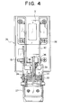
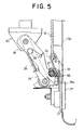
- the opening open/closure device 26 includes a bracket 32 attached to the cylindrical wall 12a, a shutter 27 pivotably joined to the bracket 32 via a connecting shaft 33, shutter springs 34 for energizing the shutter 27 around the connecting shaft 33 so that the shutter 27 closes the opening, a solenoid 31 fixed on the bracket 32, a plunger 30 that is actuated at right angle to the connecting shaft 33 by the electromagnetic action of the solenoid 31, and a link 29 for joining the shutter 27 and the plunger 30.
- the opening open/closure device 26 further includes a supporting pivot 38 attached to the link 29 parallel to the connecting shaft 33, and a shutter lock arm 36 pivotably supported around the supporting pivot 38.
- the shutter lock arm 36 has a hollow portion 37 shaped so as to engage an outer peripheral surface of the connecting shaft33.
- the shutter lock arm 36 is formed from a metallic material so as stainless steel and having a surface that is subjected to tufftriding treatment.
- the opening open/closure device 26 further includes shutter lock spring means 39 for locking the shutter 27 by applying spring force to the shutter lock arm 36 pivoted around the supporting pivot 38 thereby pressing the hollow portion 37 on the outer peripheral surface of the connecting shaft33.
- the connecting shaft 33 is provided with a sleeve 40 having an outer peripheral surface, which engages to the hollow portion 37.
- the sleeve 40 is formed from material, preferably fluorine resin, which is softer than the shutter lock arm 36.
- the sleeve 40 is positioned at a center portion of the connecting shaft 33 along the longitudinal direction of the connecting shaft 33.
- the connecting shaft 33 is provided with a first axis portion 33a having substantially the same outside diameter as that of the sleeve 40, and a second axis portion 33b formed at one end of the first axis portion 33a.
- the sleeve 40 is sandwiched between the first axis portion 33a and a pipe 41 fitted around the outer periphery of the second axis portion 33b.
- the sleeve 40 is made of softer material than that of the shutter lock arm 36, wearing down the hollow portion 37 that is formed on the shutter lock arm 36 can be reduced. Accordingly, the hollow portion 37 is prevented from being held in a state of being hollowed over the connecting shaft 33 because the hollow portion 37 is not greatly worn down, so that the chip ice that has been stored in the chip ice stocker 12 can be securely delivered to a user when the user desires.
- Fig. 7 illustrates a main part of a second embodiment of the present invention.
- the sleeve 40 is fitted around a ring groove 42 formed on a center portion of the outer periphery surface of the connecting shaft 33.
- Other arrangements than above is the same as those in the first embodiment of the present invention.
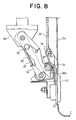
- Fig. 8 illustrates a main part of a third embodiment of the present invention.
- a shutter lock arm 36' is made of harder material than that of a connecting shaft 33.
- a hollow portion 37' that is formed at the shutter lock arm 36' is suppressed, so that the hollow portion 37' is not held in a state of being hollowed over the connecting shaft 33.
- chip ice that has been stored in the chip ice stocker can be securely delivered to a user when the user desires.
Landscapes
- Engineering & Computer Science (AREA)
- Physics & Mathematics (AREA)
- Mechanical Engineering (AREA)
- Thermal Sciences (AREA)
- General Engineering & Computer Science (AREA)
- Chemical & Material Sciences (AREA)
- Crystallography & Structural Chemistry (AREA)
- Confectionery (AREA)
Applications Claiming Priority (3)
| Application Number | Priority Date | Filing Date | Title |
|---|---|---|---|
| JP200321/97 | 1997-07-25 | ||
| JP20032197 | 1997-07-25 | ||
| JP20032197 | 1997-07-25 |
Publications (3)
| Publication Number | Publication Date |
|---|---|
| EP0893658A2 true EP0893658A2 (fr) | 1999-01-27 |
| EP0893658A3 EP0893658A3 (fr) | 1999-08-04 |
| EP0893658B1 EP0893658B1 (fr) | 2003-01-02 |
Family
ID=16422365
Family Applications (1)
| Application Number | Title | Priority Date | Filing Date |
|---|---|---|---|
| EP98113892A Expired - Lifetime EP0893658B1 (fr) | 1997-07-25 | 1998-07-24 | Distributeur de glace pour fabriquer et livrer de la glace en copeaux au consommateur |
Country Status (3)
| Country | Link |
|---|---|
| US (1) | US6009718A (fr) |
| EP (1) | EP0893658B1 (fr) |
| DE (1) | DE69810396T2 (fr) |
Cited By (1)
| Publication number | Priority date | Publication date | Assignee | Title |
|---|---|---|---|---|
| CN107166835A (zh) * | 2017-07-05 | 2017-09-15 | 海宁文硕科技咨询有限公司 | 一种改进的旋转送冰器 |
Families Citing this family (8)
| Publication number | Priority date | Publication date | Assignee | Title |
|---|---|---|---|---|
| JP4293652B2 (ja) * | 1998-10-21 | 2009-07-08 | ホシザキ電機株式会社 | 氷ディスペンサー |
| JP3702204B2 (ja) * | 2001-08-13 | 2005-10-05 | ホシザキ電機株式会社 | 貯氷庫の氷放出機構部 |
| US6959452B2 (en) * | 2002-09-26 | 2005-11-01 | Michael S. Bradbury | Breathable liquidproof protective gloves and cooling liquidproof protective gloves |
| US6990827B2 (en) * | 2002-10-28 | 2006-01-31 | Bruce Elliot Antognoni | Ice making apparatus for marine vessels |
| JP4518802B2 (ja) * | 2004-01-09 | 2010-08-04 | ホシザキ電機株式会社 | 氷ディスペンサ |
| US20060277937A1 (en) * | 2005-06-10 | 2006-12-14 | Manitowoc Foodservice Companies.Inc. | Ice making machine and method of controlling an ice making machine |
| CN103486804A (zh) * | 2013-09-18 | 2014-01-01 | 泰州乐金电子冷机有限公司 | 联动装置及包括其的冰箱冰水分配器 |
| US11566832B2 (en) * | 2021-01-27 | 2023-01-31 | Ellen Li LIAO | Ice shaver |
Citations (1)
| Publication number | Priority date | Publication date | Assignee | Title |
|---|---|---|---|---|
| JPH04187961A (ja) | 1990-11-21 | 1992-07-06 | Sanyo Electric Co Ltd | アイスディスペンサ |
Family Cites Families (8)
| Publication number | Priority date | Publication date | Assignee | Title |
|---|---|---|---|---|
| US3667724A (en) * | 1970-06-10 | 1972-06-06 | Cornelius Co | Solenoid actuated dispensing valve |
| US3804124A (en) * | 1972-10-12 | 1974-04-16 | Bloom Eng Co Inc | Three lever valve with relief port |
| US4771609A (en) * | 1987-06-01 | 1988-09-20 | Hoshizaki Electric Co., Ltd. | Ice making machine |
| US5129547A (en) * | 1988-07-14 | 1992-07-14 | Charles Fisher | Cable operated ice dispensing door |
| JP2573718B2 (ja) * | 1990-04-23 | 1997-01-22 | 松下電器産業株式会社 | ノイズ低減装置 |
| JP2528868Y2 (ja) * | 1990-04-24 | 1997-03-12 | ホシザキ電機株式会社 | 氷ディスペンサの扉開閉装置 |
| JP2562075Y2 (ja) * | 1992-09-14 | 1998-02-04 | ホシザキ電機株式会社 | 氷ストッカのための貯氷検出装置 |
| US5531079A (en) * | 1993-10-07 | 1996-07-02 | Tatematsu; Susumu | Bearing structure for auger-type ice making machines |
-
1998
- 1998-07-24 DE DE69810396T patent/DE69810396T2/de not_active Expired - Fee Related
- 1998-07-24 EP EP98113892A patent/EP0893658B1/fr not_active Expired - Lifetime
- 1998-07-24 US US09/121,867 patent/US6009718A/en not_active Expired - Fee Related
Patent Citations (1)
| Publication number | Priority date | Publication date | Assignee | Title |
|---|---|---|---|---|
| JPH04187961A (ja) | 1990-11-21 | 1992-07-06 | Sanyo Electric Co Ltd | アイスディスペンサ |
Cited By (1)
| Publication number | Priority date | Publication date | Assignee | Title |
|---|---|---|---|---|
| CN107166835A (zh) * | 2017-07-05 | 2017-09-15 | 海宁文硕科技咨询有限公司 | 一种改进的旋转送冰器 |
Also Published As
| Publication number | Publication date |
|---|---|
| EP0893658A3 (fr) | 1999-08-04 |
| DE69810396T2 (de) | 2003-08-21 |
| DE69810396D1 (de) | 2003-02-06 |
| EP0893658B1 (fr) | 2003-01-02 |
| US6009718A (en) | 2000-01-04 |
Similar Documents
| Publication | Publication Date | Title |
|---|---|---|
| US6009718A (en) | Ice dispenser for producing chip ice to deliver the same to user | |
| CA1147567A (fr) | Refrigerateur a regard d'acces aux cubes de glace sur la porte du congelateur | |
| US6257009B1 (en) | Ice dispenser | |
| US8479531B2 (en) | Liquid containing bag and frozen dessert manufacturing apparatus using the same | |
| US20100294618A1 (en) | Ice Agitation and Dispensing Device and Method | |
| US4049161A (en) | Ice making and vending machine | |
| US8469232B2 (en) | Ice agitation and dispensing device and method | |
| CA2372129A1 (fr) | Appareil servant a melanger la creme glacee dans un distributeur automatique de creme glacee | |
| JP3575140B2 (ja) | 自動販売機の水回路 | |
| EP1186241A1 (fr) | Appareillage pour vender de la glace | |
| CN1332164C (zh) | 冰块分送器 | |
| JP4573680B2 (ja) | 冷菓製造装置 | |
| JPH0298398A (ja) | 洗濯機の洗剤自動投入装置 | |
| KR19990050346A (ko) | 복합냉장고의 디스펜스기능 관련 배관시스템 구조 | |
| JP2000224959A (ja) | フローズン飲料ディスペンサおよびその飲料タンクの洗浄方法 | |
| KR100343694B1 (ko) | 냉장고의 얼음 엉김 방지장치 및 방법 | |
| JP3497973B2 (ja) | オーガー式製氷機 | |
| JP2510831B2 (ja) | 冷菓製造装置 | |
| JPH1194415A (ja) | アイスディスペンサ | |
| KR20000007867A (ko) | 냉장고의 얼음모터 제어 방법 | |
| KR0133333B1 (ko) | 냉장고의 급수장치 | |
| CN117515880A (zh) | 一种排水装置及空调器 | |
| JP2002315676A (ja) | 飲料抽出装置 | |
| KR100343678B1 (ko) | 냉장고용제빙기의검빙레버제어방법 | |
| JP4194342B2 (ja) | 冷菓製造装置 |
Legal Events
| Date | Code | Title | Description |
|---|---|---|---|
| PUAI | Public reference made under article 153(3) epc to a published international application that has entered the european phase |
Free format text: ORIGINAL CODE: 0009012 |
|
| AK | Designated contracting states |
Kind code of ref document: A2 Designated state(s): DE FR GB NL |
|
| AX | Request for extension of the european patent |
Free format text: AL;LT;LV;MK;RO;SI |
|
| PUAL | Search report despatched |
Free format text: ORIGINAL CODE: 0009013 |
|
| AK | Designated contracting states |
Kind code of ref document: A3 Designated state(s): AT BE CH CY DE DK ES FI FR GB GR IE IT LI LU MC NL PT SE |
|
| AX | Request for extension of the european patent |
Free format text: AL;LT;LV;MK;RO;SI |
|
| 17P | Request for examination filed |
Effective date: 19990806 |
|
| AKX | Designation fees paid |
Free format text: DE FR GB NL |
|
| 17Q | First examination report despatched |
Effective date: 20010607 |
|
| GRAG | Despatch of communication of intention to grant |
Free format text: ORIGINAL CODE: EPIDOS AGRA |
|
| GRAG | Despatch of communication of intention to grant |
Free format text: ORIGINAL CODE: EPIDOS AGRA |
|
| GRAH | Despatch of communication of intention to grant a patent |
Free format text: ORIGINAL CODE: EPIDOS IGRA |
|
| GRAH | Despatch of communication of intention to grant a patent |
Free format text: ORIGINAL CODE: EPIDOS IGRA |
|
| GRAA | (expected) grant |
Free format text: ORIGINAL CODE: 0009210 |
|
| AK | Designated contracting states |
Kind code of ref document: B1 Designated state(s): DE FR GB NL |
|
| REG | Reference to a national code |
Ref country code: GB Ref legal event code: FG4D Free format text: 20030102 |
|
| REF | Corresponds to: |
Ref document number: 69810396 Country of ref document: DE Date of ref document: 20030206 Kind code of ref document: P |
|
| ET | Fr: translation filed | ||
| PLBE | No opposition filed within time limit |
Free format text: ORIGINAL CODE: 0009261 |
|
| STAA | Information on the status of an ep patent application or granted ep patent |
Free format text: STATUS: NO OPPOSITION FILED WITHIN TIME LIMIT |
|
| 26N | No opposition filed |
Effective date: 20031003 |
|
| PGFP | Annual fee paid to national office [announced via postgrant information from national office to epo] |
Ref country code: FR Payment date: 20090710 Year of fee payment: 12 |
|
| PGFP | Annual fee paid to national office [announced via postgrant information from national office to epo] |
Ref country code: NL Payment date: 20090715 Year of fee payment: 12 Ref country code: GB Payment date: 20090722 Year of fee payment: 12 Ref country code: DE Payment date: 20090716 Year of fee payment: 12 |
|
| REG | Reference to a national code |
Ref country code: NL Ref legal event code: V1 Effective date: 20110201 |
|
| GBPC | Gb: european patent ceased through non-payment of renewal fee |
Effective date: 20100724 |
|
| REG | Reference to a national code |
Ref country code: FR Ref legal event code: ST Effective date: 20110331 |
|
| PG25 | Lapsed in a contracting state [announced via postgrant information from national office to epo] |
Ref country code: DE Free format text: LAPSE BECAUSE OF NON-PAYMENT OF DUE FEES Effective date: 20110201 |
|
| REG | Reference to a national code |
Ref country code: DE Ref legal event code: R119 Ref document number: 69810396 Country of ref document: DE Effective date: 20110201 |
|
| PG25 | Lapsed in a contracting state [announced via postgrant information from national office to epo] |
Ref country code: NL Free format text: LAPSE BECAUSE OF NON-PAYMENT OF DUE FEES Effective date: 20110201 Ref country code: FR Free format text: LAPSE BECAUSE OF NON-PAYMENT OF DUE FEES Effective date: 20100802 |
|
| PG25 | Lapsed in a contracting state [announced via postgrant information from national office to epo] |
Ref country code: GB Free format text: LAPSE BECAUSE OF NON-PAYMENT OF DUE FEES Effective date: 20100724 |