EP0893673A1 - Gasdurchfluss-Sensor und einen solchen Sensor aufweisende Atmungsunterstützungsvorrichtung - Google Patents
Gasdurchfluss-Sensor und einen solchen Sensor aufweisende Atmungsunterstützungsvorrichtung Download PDFInfo
- Publication number
- EP0893673A1 EP0893673A1 EP98401828A EP98401828A EP0893673A1 EP 0893673 A1 EP0893673 A1 EP 0893673A1 EP 98401828 A EP98401828 A EP 98401828A EP 98401828 A EP98401828 A EP 98401828A EP 0893673 A1 EP0893673 A1 EP 0893673A1
- Authority
- EP
- European Patent Office
- Prior art keywords
- gas flow
- flow sensor
- permeable
- sensor according
- slots
- Prior art date
- Legal status (The legal status is an assumption and is not a legal conclusion. Google has not performed a legal analysis and makes no representation as to the accuracy of the status listed.)
- Granted
Links
- 230000029058 respiratory gaseous exchange Effects 0.000 title description 2
- 238000011144 upstream manufacturing Methods 0.000 claims abstract description 24
- 238000010438 heat treatment Methods 0.000 claims description 6
- 230000000241 respiratory effect Effects 0.000 claims description 6
- 238000010079 rubber tapping Methods 0.000 claims description 6
- 238000005259 measurement Methods 0.000 claims description 5
- 230000000295 complement effect Effects 0.000 claims description 3
- 230000003434 inspiratory effect Effects 0.000 claims description 3
- 208000031968 Cadaver Diseases 0.000 description 17
- 241001080024 Telles Species 0.000 description 4
- 238000004804 winding Methods 0.000 description 4
- 238000009530 blood pressure measurement Methods 0.000 description 3
- 239000000463 material Substances 0.000 description 3
- 229920004943 Delrin® Polymers 0.000 description 1
- 229920000297 Rayon Polymers 0.000 description 1
- 229910052782 aluminium Inorganic materials 0.000 description 1
- XAGFODPZIPBFFR-UHFFFAOYSA-N aluminium Chemical compound [Al] XAGFODPZIPBFFR-UHFFFAOYSA-N 0.000 description 1
- 230000004323 axial length Effects 0.000 description 1
- 230000005494 condensation Effects 0.000 description 1
- 238000009833 condensation Methods 0.000 description 1
- 230000001627 detrimental effect Effects 0.000 description 1
- 230000002349 favourable effect Effects 0.000 description 1
- 230000006698 induction Effects 0.000 description 1
- 238000004519 manufacturing process Methods 0.000 description 1
- 229910052751 metal Inorganic materials 0.000 description 1
- 239000002184 metal Substances 0.000 description 1
- 238000000465 moulding Methods 0.000 description 1
- 230000002093 peripheral effect Effects 0.000 description 1
- 239000002964 rayon Substances 0.000 description 1
Images

Classifications
-
- G—PHYSICS
- G01—MEASURING; TESTING
- G01F—MEASURING VOLUME, VOLUME FLOW, MASS FLOW OR LIQUID LEVEL; METERING BY VOLUME
- G01F1/00—Measuring the volume flow or mass flow of fluid or fluent solid material wherein the fluid passes through a meter in a continuous flow
- G01F1/05—Measuring the volume flow or mass flow of fluid or fluent solid material wherein the fluid passes through a meter in a continuous flow by using mechanical effects
- G01F1/34—Measuring the volume flow or mass flow of fluid or fluent solid material wherein the fluid passes through a meter in a continuous flow by using mechanical effects by measuring pressure or differential pressure
- G01F1/36—Measuring the volume flow or mass flow of fluid or fluent solid material wherein the fluid passes through a meter in a continuous flow by using mechanical effects by measuring pressure or differential pressure the pressure or differential pressure being created by the use of flow constriction
- G01F1/40—Details of construction of the flow constriction devices
Definitions
- the invention relates to a gas flow sensor.
- the invention relates more particularly to a sensor gas flow rate, of the type in which two intake pipes upstream and downstream pressure, which are each connected to a pressure sensor pressure, open into a gas flow channel in which a permeable element extends axially at least between through ends of the two intake conduits pressure.
- Such sensors are used in particular in respiratory assistance devices to know the value of inspired flow or flow expired by a patient.
- the flow measurement must be particularly precise to allow operation optimal respiratory support, including so as to assure the patient a comfort of use satisfactory.
- the corrugated sheet is found taken between two portions of the flat sheet so as to delimit between these two portions axial passages for gas flow.
- the object of the invention is therefore to propose a new design of a gas flow sensor, and in particular a new design of the permeable element forming loss of load, which ensures very good accuracy and very good representativeness of pressure measurements while reducing the manufacturing cost.
- the invention proposes a flow sensor for gas of the type described above, characterized in that the permeable element is produced in the form of a body which has a complementary shape in cross section that of the canal, and which has slots extending radially around its axis so as to open out radially in an external lateral surface of the body, and in that the slots extend axially over the entire length permeable body.
- the invention also relates to an assistive device respiratory, characterized in that it includes a sensor for gas flow having any of the characteristics previous.
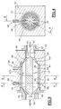
- a sensor 10 which is intended to measure a gas flow.
- the sensor 10 thus comprises an external body 12 which is pierced with a central bore opening 14 of axis A1 in which is intended to be introduced a tubular sleeve 16.
- An internal cylindrical surface 18 of the socket 16 limits a channel 20 through which the gas entering the sensor flows 10 by an input port 22 and which emerges therefrom by a port of exit 24.
- the flow sensor 10 which is shown here is present in the form of an independent and autonomous block entirely contained inside the external body 12.
- such a sensor 10 can advantageously be integrated into a complex pneumatic assembly such as the valve block of a breathing device, the block valves then forming the external body.
- the sensor is then interposed in an inspiratory or expiratory circuit of the device to know with great precision the volumes of gas inspired or exhaled by the patient.
- the senor 10 has two pressure tapping pipes 26, 28 which open into the gas flow channel 20 and which are each intended to be connected to a pressure sensor (not shown).
- each conduit 26, 28 comprises a line 30, pierced in the main body 12 of the sensor 10, and a through end arranged in the socket tubular 16.
- the socket 16 has, in its surface lateral cylindrical outer 32, two annular grooves, respectively upstream 34 and downstream 36, and, at the bottom of each of these grooves 34, 36, there is a series of holes radials 38 which open radially outward into one of the grooves 34, 36 and radially inwards in the internal cylindrical surface 18 of the socket 16.
- each of the intake conduits 26, 28 pressure open axially opposite the grooves annulars 34, 36.
- each of the grooves 34, 36 forms, with the corresponding holes 38, one end branched through outlet for each of the conduits 26, 28.
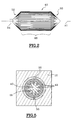
- the permeable body 40 of the sensor 10 is made in the form of a body which has a section central cylindrical 48 and two conical end sections, respectively upstream 50 and downstream 52, which are each pointed upstream and downstream respectively.
- the half angles at the top of the conical sections 50, 52 are for example 45 °.
- the conical section downstream 52 is provided with a cylindrical stud 54 which extends it axially downstream.
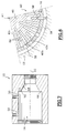
- the central section 48 thus has, in section transverse, a shape complementary to that of the canal flow 20, that is to say in this case a section circular with the same diameter as channel 20.
- the permeable body 40 comprises a series radially oriented slots 42 which are distributed so regular around the axis A1 and which extend axially over the entire length of the permeable body 40 for the purpose of provide a passage for the gas flowing through the sensor 10.
- the slots 42 all open radially outwards in an external cylindrical surface 44 of the permeable body 40 but we can see that they have different radial depths.
- the depth of the slots 42 never exceeds the permeable body radius 40 and this depth is even less than this radius so as to spare, in the center of the permeable body 40, a full axial core 46 which preserves its rigidity.
- the three series of slots 42a, 42b, 42c are arranged in such a way that a very deep slot 42c is framed by two slots 42b of average depth. Of even, a shallow slot 42a is also framed by two slits of average depth 42b.
- the slots 42 are parallel flank slots 66.
- the flanks 66 which delimit them laterally are slightly tilted relative to each other to give the slot 42 a V shape in cross section.
- indexing angular permeable body 40 relative to the socket 16.
- these angular indexing means can be made using a pin 56 which is integral with the socket 16 and which extends radially inwards so to be engaged in one of the slots 42 of the permeable body 40.
- the holes 38 of the socket 16 are distributed angularly so that, for each of the two conduits 26, 28, there is at least one bore 38 which opens out next to a slot in each of the three series of slots 42a, 42b, 42c of different depths.
- the sleeve 16 does not include bore 38 which opens opposite the pipe 30 corresponding to the external body 12.
- a pawn orientation 58 axial orientation which is for example integral with the external body 12, is intended to be engaged in a corresponding indexing hole, also oriented axial, formed in an annular transverse end face upstream 62 of the socket 16.
- the socket 16 is intended to bear axially upstream against a annular transverse face of shoulder 64 of bore 14 of the external body 12.
- This annular transverse face of shoulder 64 is extended upstream by a frustoconical surface 68, pointing upstream and having a half angle at the top about 30 °.
- the axial length of the central section 48 of the permeable body 40 is such that it extends axially upstream of the radial holes 38 of the upstream pressure tapping pipe 26 and downstream of the bores radials 38 of the downstream position conduit 28.
- the upstream and downstream pressure taps are performed in an area of the sensor 10 in which the gas flows inside the slots 42.
- the gas flow in the slots 42 is laminar or quasi-laminar, which is favorable for large accuracy of upstream and downstream pressure measurements, and by consequence of the flow measurement that can be performed thanks to sensor 10.
- the permeable body 40 can equally be produced in plastic such as "delrin” or in material metallic, for example aluminum.
- the flow sensor 10 When the flow sensor 10 is used for the measurement of air volume inspired or exhaled by a patient, it can be useful to provide means for heating the body permeable 40 to avoid any risk of air condensation on the latter.
- This heating can be carried out in various ways. You can choose to heat from the outside, i.e. through the external body 12, where one can choose to do it from the inside, for example by having a heating resistor in the central core 46 of the body permeable 42.
- the permeable body 40 is made of a material metallic with adequate magnetic properties, this heating can also be achieved by induction.
- the permeable body 40 can be produced from a massive starting block in which the slots 42 are cut to using a three size bur. However, we can also plan to make the permeable body 40 by molding, the slots 42 then being made directly from material.
- slots 42 and their width may vary depending on gas flow flowing through sensor 10 and depending on the loss load that you want to achieve with the body permeable 40.
Landscapes
- Physics & Mathematics (AREA)
- Fluid Mechanics (AREA)
- General Physics & Mathematics (AREA)
- Measurement Of The Respiration, Hearing Ability, Form, And Blood Characteristics Of Living Organisms (AREA)
- Sampling And Sample Adjustment (AREA)
- Investigating Or Analysing Biological Materials (AREA)
- Investigating Or Analyzing Materials By The Use Of Electric Means (AREA)
- Investigating Or Analyzing Materials By The Use Of Fluid Adsorption Or Reactions (AREA)
- Measuring Volume Flow (AREA)
- Respiratory Apparatuses And Protective Means (AREA)
- Measuring Fluid Pressure (AREA)
- Measuring Oxygen Concentration In Cells (AREA)
Applications Claiming Priority (2)
| Application Number | Priority Date | Filing Date | Title |
|---|---|---|---|
| FR9709380A FR2766568B1 (fr) | 1997-07-23 | 1997-07-23 | Capteur de debit de gaz et appareil d'assistance respiratoire comportant un tel capteur |
| FR9709380 | 1997-07-23 |
Publications (2)
| Publication Number | Publication Date |
|---|---|
| EP0893673A1 true EP0893673A1 (de) | 1999-01-27 |
| EP0893673B1 EP0893673B1 (de) | 2009-02-11 |
Family
ID=9509550
Family Applications (1)
| Application Number | Title | Priority Date | Filing Date |
|---|---|---|---|
| EP98401828A Expired - Lifetime EP0893673B1 (de) | 1997-07-23 | 1998-07-20 | Gasdurchfluss-Sensor und einen solchen Sensor aufweisende Atmungsunterstützungsvorrichtung |
Country Status (9)
| Country | Link |
|---|---|
| US (1) | US6164141A (de) |
| EP (1) | EP0893673B1 (de) |
| JP (2) | JP4060449B2 (de) |
| AT (1) | ATE422663T1 (de) |
| CA (1) | CA2242882C (de) |
| DE (1) | DE69840535D1 (de) |
| FR (1) | FR2766568B1 (de) |
| MA (1) | MA24597A1 (de) |
| TR (1) | TR199801385A1 (de) |
Cited By (4)
| Publication number | Priority date | Publication date | Assignee | Title |
|---|---|---|---|---|
| RU2284475C2 (ru) * | 2004-11-11 | 2006-09-27 | Генрих Карлович Зиберт | Сужающее устройство |
| RU2389979C2 (ru) * | 2008-06-23 | 2010-05-20 | Николай Леонидович Егоров | Расходомер кассетный |
| CN103070686A (zh) * | 2012-12-25 | 2013-05-01 | 合肥博谐电子科技有限公司 | 基于双差压传感器测量人体呼吸力学参数的装置和方法 |
| FR2992845A1 (fr) * | 2012-07-05 | 2014-01-10 | Isp System | Dispositif de mesure d'un flux gazeux pour l'imagerie medicale |
Families Citing this family (15)
| Publication number | Priority date | Publication date | Assignee | Title |
|---|---|---|---|---|
| JP2000329225A (ja) | 1999-05-18 | 2000-11-30 | Honda Motor Co Ltd | 変速機の制御装置 |
| US6865957B1 (en) * | 2002-04-17 | 2005-03-15 | Nathaniel Hughes | Adaptable fluid mass flow meter device |
| AU2003251311A1 (en) * | 2002-05-24 | 2003-12-12 | Mykrolis Corporation | Slotted flow restrictor for a mass flow meter |
| JP2005538846A (ja) * | 2002-09-16 | 2005-12-22 | アエロクライン・アクチボラゲット | 浄化器 |
| DE10259395A1 (de) * | 2002-12-19 | 2004-07-22 | Festo Ag & Co. | Anschlussstück für Fluidleitungen |
| DE10320776B4 (de) * | 2003-05-09 | 2009-12-24 | Zf Friedrichshafen Ag | Vorrichtung zur Kompensation von viskosen Eigenschaften eines hydraulischen Mediums in einer hydraulischen Druckleitung |
| US7878980B2 (en) * | 2003-06-13 | 2011-02-01 | Treymed, Inc. | Gas flow diverter for respiratory monitoring device |
| US7478565B2 (en) * | 2007-01-23 | 2009-01-20 | Young Alan M | Method & apparatus for fluid flow rate and density measurement |
| WO2011144641A1 (en) | 2010-05-17 | 2011-11-24 | Mindray Medical Sweden Ab | Coaxial means for measuring a flow and a method of measuring a flow |
| US8393228B2 (en) | 2010-05-18 | 2013-03-12 | Mindray Medical Sweden Ab | Method and system for measuring a flow |
| US7992453B1 (en) * | 2011-01-14 | 2011-08-09 | Cameron International Corporation | Erosion-resistant insert for flow measurement devices |
| WO2013088351A1 (en) * | 2011-12-12 | 2013-06-20 | Koninklijke Philips Electronics N.V. | Differential pressure flow sensor |
| WO2014184377A2 (en) * | 2013-05-17 | 2014-11-20 | Resmed Paris Sas | Flow diffuser and sound cone |
| CN105091958B (zh) * | 2015-09-23 | 2018-09-04 | 陕西易度仪器仪表有限公司 | 一种层流流量计 |
| CN108088511B (zh) * | 2016-11-21 | 2020-04-10 | 马宁敏 | 一种薄壁圆筒形离心式气体流量计 |
Citations (4)
| Publication number | Priority date | Publication date | Assignee | Title |
|---|---|---|---|---|
| DE2034097A1 (de) * | 1970-07-09 | 1972-01-20 | Siemens Ag | Stromungsmesser, insbesondere Atemstrom rezeptor |
| EP0295575A1 (de) * | 1987-06-16 | 1988-12-21 | Institut Po Technitscheska Kibernetika I Robotika | Durchflussumformer, insbesondere für die Diagnostik von Lungenerkrankungen |
| EP0428364A1 (de) * | 1989-11-13 | 1991-05-22 | Dxl International Inc. | Strömungsmesser |
| EP0547617A1 (de) * | 1991-12-18 | 1993-06-23 | Pierre Delajoud | Massenströmungsmesser mit einschnürendem Element |
Family Cites Families (3)
| Publication number | Priority date | Publication date | Assignee | Title |
|---|---|---|---|---|
| JPS5735718A (en) * | 1980-08-12 | 1982-02-26 | Citizen Watch Co Ltd | Rectifying element |
| US4800754A (en) * | 1987-10-07 | 1989-01-31 | Sierra Instruments, Inc. | Wide-range, adjustable flowmeter |
| US5804717A (en) * | 1996-04-05 | 1998-09-08 | Mks Instruments, Inc. | Mass flow transducer having extended flow rate measurement range |
-
1997
- 1997-07-23 FR FR9709380A patent/FR2766568B1/fr not_active Expired - Lifetime
-
1998
- 1998-07-01 MA MA25153A patent/MA24597A1/fr unknown
- 1998-07-06 CA CA002242882A patent/CA2242882C/en not_active Expired - Lifetime
- 1998-07-17 TR TR1998/01385A patent/TR199801385A1/xx unknown
- 1998-07-20 DE DE69840535T patent/DE69840535D1/de not_active Expired - Lifetime
- 1998-07-20 AT AT98401828T patent/ATE422663T1/de not_active IP Right Cessation
- 1998-07-20 EP EP98401828A patent/EP0893673B1/de not_active Expired - Lifetime
- 1998-07-21 US US09/120,001 patent/US6164141A/en not_active Expired - Lifetime
- 1998-07-23 JP JP20822298A patent/JP4060449B2/ja not_active Expired - Lifetime
-
2007
- 2007-08-17 JP JP2007213049A patent/JP2007307410A/ja not_active Withdrawn
Patent Citations (4)
| Publication number | Priority date | Publication date | Assignee | Title |
|---|---|---|---|---|
| DE2034097A1 (de) * | 1970-07-09 | 1972-01-20 | Siemens Ag | Stromungsmesser, insbesondere Atemstrom rezeptor |
| EP0295575A1 (de) * | 1987-06-16 | 1988-12-21 | Institut Po Technitscheska Kibernetika I Robotika | Durchflussumformer, insbesondere für die Diagnostik von Lungenerkrankungen |
| EP0428364A1 (de) * | 1989-11-13 | 1991-05-22 | Dxl International Inc. | Strömungsmesser |
| EP0547617A1 (de) * | 1991-12-18 | 1993-06-23 | Pierre Delajoud | Massenströmungsmesser mit einschnürendem Element |
Cited By (6)
| Publication number | Priority date | Publication date | Assignee | Title |
|---|---|---|---|---|
| RU2284475C2 (ru) * | 2004-11-11 | 2006-09-27 | Генрих Карлович Зиберт | Сужающее устройство |
| RU2389979C2 (ru) * | 2008-06-23 | 2010-05-20 | Николай Леонидович Егоров | Расходомер кассетный |
| FR2992845A1 (fr) * | 2012-07-05 | 2014-01-10 | Isp System | Dispositif de mesure d'un flux gazeux pour l'imagerie medicale |
| WO2014006277A3 (fr) * | 2012-07-05 | 2014-07-03 | Isp System | Dispositif de mesure d'un flux gazeux pour l'imagerie medicale |
| CN103070686A (zh) * | 2012-12-25 | 2013-05-01 | 合肥博谐电子科技有限公司 | 基于双差压传感器测量人体呼吸力学参数的装置和方法 |
| CN103070686B (zh) * | 2012-12-25 | 2015-05-06 | 合肥博谐电子科技有限公司 | 基于双差压传感器测量人体呼吸力学参数的装置和方法 |
Also Published As
| Publication number | Publication date |
|---|---|
| TR199801385A1 (xx) | 1999-02-22 |
| FR2766568A1 (fr) | 1999-01-29 |
| JP4060449B2 (ja) | 2008-03-12 |
| CA2242882C (en) | 2009-09-08 |
| MA24597A1 (fr) | 1999-04-01 |
| FR2766568B1 (fr) | 1999-09-10 |
| CA2242882A1 (en) | 1999-01-23 |
| JP2007307410A (ja) | 2007-11-29 |
| US6164141A (en) | 2000-12-26 |
| ATE422663T1 (de) | 2009-02-15 |
| EP0893673B1 (de) | 2009-02-11 |
| JPH11137691A (ja) | 1999-05-25 |
| DE69840535D1 (de) | 2009-03-26 |
Similar Documents
| Publication | Publication Date | Title |
|---|---|---|
| EP0893673B1 (de) | Gasdurchfluss-Sensor und einen solchen Sensor aufweisende Atmungsunterstützungsvorrichtung | |
| EP2991548B1 (de) | System und vorrichtung zur messung der strömungsgeschwindigkeit von exspiratorischem oder inhaliertem luftstrom | |
| CA2553860C (fr) | Canal de refroidissement menage dans une paroi | |
| FR2811879A1 (fr) | Detecteur de courant respiratoire | |
| FR2551545A1 (fr) | Debitmetre presentant une derivation reglable a ecoulement laminaire | |
| FR2833347A1 (fr) | Sonde multifonction pour aeronef | |
| FR3032254A1 (de) | ||
| EP1963023B1 (de) | Vorrichtung zum sprühen einer flüssigkeit | |
| EP1956281B1 (de) | Vorrichtung zur Schalldämpfung für Zuführkreislauf von gasförmigen Fluiden | |
| EP1209348A1 (de) | Schalldämpfereinrichtung, insbesondere für turbogeladene Verbrennungsmotoren | |
| FR2769957A1 (fr) | Oscillateur fluidique a fente prolongee | |
| WO2011048323A2 (fr) | Dispositif d'absorption acoustique | |
| EP3973235A1 (de) | Wärmetauscher und zugehöriges wärmetauschersystem für ein fahrzeug | |
| EP0864790B1 (de) | Scheiben für eine Mischerpatrone und damit ausgestattete Patrone | |
| EP1747834B1 (de) | In einem Wandteil versehenen Kühlkanal | |
| WO2022106961A1 (fr) | Débitmètre et méthode de mesure de consommation d'eau | |
| FR2873796A1 (fr) | Radiateur de chauffage avec distribution d'eau centrale | |
| EP1307273B1 (de) | Filtergehäuse für mikrofiltration | |
| FR2640351A1 (fr) | Redresseur de l'ecoulement d'un fluide dans une conduite | |
| CH355608A (fr) | Machine à mouler une matière thermoplastique par injection | |
| EP0581636B1 (de) | Stromverbesserer für eine Entspannungsstation und Messvorrichtung | |
| FR2832672A1 (fr) | Moyeu de roue et roue ayant un tel moyeu | |
| FR3143664A1 (fr) | Collecteur pour capteur de gaz | |
| JPH0774750B2 (ja) | 層流素子 | |
| EP0160611A1 (de) | Einrichtung für das Regeln eines Fluidums, insbesondere Wasser in einer Leitung |
Legal Events
| Date | Code | Title | Description |
|---|---|---|---|
| PUAI | Public reference made under article 153(3) epc to a published international application that has entered the european phase |
Free format text: ORIGINAL CODE: 0009012 |
|
| AK | Designated contracting states |
Kind code of ref document: A1 Designated state(s): AT BE CH DE DK ES FI GB GR IE IT LI LU MC NL PT SE |
|
| AX | Request for extension of the european patent |
Free format text: AL;LT;LV;MK;RO;SI |
|
| 17P | Request for examination filed |
Effective date: 19990316 |
|
| AKX | Designation fees paid |
Free format text: AT BE CH DE DK ES FI GB GR IE IT LI LU MC NL PT SE |
|
| RAP1 | Party data changed (applicant data changed or rights of an application transferred) |
Owner name: SAIME |
|
| GRAP | Despatch of communication of intention to grant a patent |
Free format text: ORIGINAL CODE: EPIDOSNIGR1 |
|
| GRAS | Grant fee paid |
Free format text: ORIGINAL CODE: EPIDOSNIGR3 |
|
| GRAA | (expected) grant |
Free format text: ORIGINAL CODE: 0009210 |
|
| AK | Designated contracting states |
Kind code of ref document: B1 Designated state(s): AT BE CH DE DK ES FI GB GR IE IT LI LU MC NL PT SE |
|
| REG | Reference to a national code |
Ref country code: GB Ref legal event code: FG4D Free format text: NOT ENGLISH |
|
| REG | Reference to a national code |
Ref country code: CH Ref legal event code: EP |
|
| REG | Reference to a national code |
Ref country code: IE Ref legal event code: FG4D Free format text: LANGUAGE OF EP DOCUMENT: FRENCH |
|
| REF | Corresponds to: |
Ref document number: 69840535 Country of ref document: DE Date of ref document: 20090326 Kind code of ref document: P |
|
| PG25 | Lapsed in a contracting state [announced via postgrant information from national office to epo] |
Ref country code: NL Free format text: LAPSE BECAUSE OF FAILURE TO SUBMIT A TRANSLATION OF THE DESCRIPTION OR TO PAY THE FEE WITHIN THE PRESCRIBED TIME-LIMIT Effective date: 20090211 Ref country code: FI Free format text: LAPSE BECAUSE OF FAILURE TO SUBMIT A TRANSLATION OF THE DESCRIPTION OR TO PAY THE FEE WITHIN THE PRESCRIBED TIME-LIMIT Effective date: 20090211 Ref country code: ES Free format text: LAPSE BECAUSE OF FAILURE TO SUBMIT A TRANSLATION OF THE DESCRIPTION OR TO PAY THE FEE WITHIN THE PRESCRIBED TIME-LIMIT Effective date: 20090522 |
|
| NLV1 | Nl: lapsed or annulled due to failure to fulfill the requirements of art. 29p and 29m of the patents act | ||
| PG25 | Lapsed in a contracting state [announced via postgrant information from national office to epo] |
Ref country code: AT Free format text: LAPSE BECAUSE OF FAILURE TO SUBMIT A TRANSLATION OF THE DESCRIPTION OR TO PAY THE FEE WITHIN THE PRESCRIBED TIME-LIMIT Effective date: 20090211 |
|
| REG | Reference to a national code |
Ref country code: IE Ref legal event code: FD4D |
|
| PG25 | Lapsed in a contracting state [announced via postgrant information from national office to epo] |
Ref country code: PT Free format text: LAPSE BECAUSE OF FAILURE TO SUBMIT A TRANSLATION OF THE DESCRIPTION OR TO PAY THE FEE WITHIN THE PRESCRIBED TIME-LIMIT Effective date: 20090713 Ref country code: IE Free format text: LAPSE BECAUSE OF FAILURE TO SUBMIT A TRANSLATION OF THE DESCRIPTION OR TO PAY THE FEE WITHIN THE PRESCRIBED TIME-LIMIT Effective date: 20090211 Ref country code: DK Free format text: LAPSE BECAUSE OF FAILURE TO SUBMIT A TRANSLATION OF THE DESCRIPTION OR TO PAY THE FEE WITHIN THE PRESCRIBED TIME-LIMIT Effective date: 20090211 |
|
| PLBE | No opposition filed within time limit |
Free format text: ORIGINAL CODE: 0009261 |
|
| STAA | Information on the status of an ep patent application or granted ep patent |
Free format text: STATUS: NO OPPOSITION FILED WITHIN TIME LIMIT |
|
| 26N | No opposition filed |
Effective date: 20091112 |
|
| BERE | Be: lapsed |
Owner name: RESMED PARIS Effective date: 20090731 |
|
| PG25 | Lapsed in a contracting state [announced via postgrant information from national office to epo] |
Ref country code: MC Free format text: LAPSE BECAUSE OF NON-PAYMENT OF DUE FEES Effective date: 20090731 |
|
| REG | Reference to a national code |
Ref country code: CH Ref legal event code: PL |
|
| PG25 | Lapsed in a contracting state [announced via postgrant information from national office to epo] |
Ref country code: LI Free format text: LAPSE BECAUSE OF NON-PAYMENT OF DUE FEES Effective date: 20090731 Ref country code: CH Free format text: LAPSE BECAUSE OF NON-PAYMENT OF DUE FEES Effective date: 20090731 |
|
| PG25 | Lapsed in a contracting state [announced via postgrant information from national office to epo] |
Ref country code: BE Free format text: LAPSE BECAUSE OF NON-PAYMENT OF DUE FEES Effective date: 20090731 |
|
| PG25 | Lapsed in a contracting state [announced via postgrant information from national office to epo] |
Ref country code: GR Free format text: LAPSE BECAUSE OF FAILURE TO SUBMIT A TRANSLATION OF THE DESCRIPTION OR TO PAY THE FEE WITHIN THE PRESCRIBED TIME-LIMIT Effective date: 20090512 |
|
| PG25 | Lapsed in a contracting state [announced via postgrant information from national office to epo] |
Ref country code: IT Free format text: LAPSE BECAUSE OF FAILURE TO SUBMIT A TRANSLATION OF THE DESCRIPTION OR TO PAY THE FEE WITHIN THE PRESCRIBED TIME-LIMIT Effective date: 20090211 |
|
| PG25 | Lapsed in a contracting state [announced via postgrant information from national office to epo] |
Ref country code: LU Free format text: LAPSE BECAUSE OF NON-PAYMENT OF DUE FEES Effective date: 20090720 |
|
| PGFP | Annual fee paid to national office [announced via postgrant information from national office to epo] |
Ref country code: SE Payment date: 20160712 Year of fee payment: 19 |
|
| PGFP | Annual fee paid to national office [announced via postgrant information from national office to epo] |
Ref country code: DE Payment date: 20170711 Year of fee payment: 20 Ref country code: GB Payment date: 20170719 Year of fee payment: 20 |
|
| REG | Reference to a national code |
Ref country code: SE Ref legal event code: EUG |
|
| PG25 | Lapsed in a contracting state [announced via postgrant information from national office to epo] |
Ref country code: SE Free format text: LAPSE BECAUSE OF NON-PAYMENT OF DUE FEES Effective date: 20170721 |
|
| REG | Reference to a national code |
Ref country code: DE Ref legal event code: R071 Ref document number: 69840535 Country of ref document: DE |
|
| REG | Reference to a national code |
Ref country code: GB Ref legal event code: PE20 Expiry date: 20180719 |
|
| PG25 | Lapsed in a contracting state [announced via postgrant information from national office to epo] |
Ref country code: GB Free format text: LAPSE BECAUSE OF EXPIRATION OF PROTECTION Effective date: 20180719 |