EP0893699B1 - Magnetischer Fühler mit einer auf den Spulenkörper aufgebrachten lineare Dünnschichtleiterabschnitte aufweisenden Erregerspule mit darauf gewickelter Detektorspule - Google Patents
Magnetischer Fühler mit einer auf den Spulenkörper aufgebrachten lineare Dünnschichtleiterabschnitte aufweisenden Erregerspule mit darauf gewickelter Detektorspule Download PDFInfo
- Publication number
- EP0893699B1 EP0893699B1 EP98113905A EP98113905A EP0893699B1 EP 0893699 B1 EP0893699 B1 EP 0893699B1 EP 98113905 A EP98113905 A EP 98113905A EP 98113905 A EP98113905 A EP 98113905A EP 0893699 B1 EP0893699 B1 EP 0893699B1
- Authority
- EP
- European Patent Office
- Prior art keywords
- bobbin
- toroidal
- magnetic sensor
- core
- groove
- Prior art date
- Legal status (The legal status is an assumption and is not a legal conclusion. Google has not performed a legal analysis and makes no representation as to the accuracy of the status listed.)
- Expired - Lifetime
Links
- 239000004020 conductor Substances 0.000 title claims description 54
- 230000005284 excitation Effects 0.000 title claims description 27
- 238000001514 detection method Methods 0.000 title claims description 21
- 239000010409 thin film Substances 0.000 title claims description 14
- 239000010408 film Substances 0.000 claims description 23
- 239000000463 material Substances 0.000 claims description 12
- 239000000088 plastic resin Substances 0.000 claims description 5
- 238000005229 chemical vapour deposition Methods 0.000 claims description 4
- 239000011368 organic material Substances 0.000 claims description 2
- 238000004804 winding Methods 0.000 description 8
- 230000013011 mating Effects 0.000 description 7
- PXHVJJICTQNCMI-UHFFFAOYSA-N Nickel Chemical compound [Ni] PXHVJJICTQNCMI-UHFFFAOYSA-N 0.000 description 6
- 229910000679 solder Inorganic materials 0.000 description 6
- RYGMFSIKBFXOCR-UHFFFAOYSA-N Copper Chemical compound [Cu] RYGMFSIKBFXOCR-UHFFFAOYSA-N 0.000 description 4
- 229910052802 copper Inorganic materials 0.000 description 4
- 239000010949 copper Substances 0.000 description 4
- 239000011888 foil Substances 0.000 description 3
- 239000010931 gold Substances 0.000 description 3
- 239000012212 insulator Substances 0.000 description 3
- 229910052759 nickel Inorganic materials 0.000 description 3
- 238000007747 plating Methods 0.000 description 3
- 238000000151 deposition Methods 0.000 description 2
- 230000004907 flux Effects 0.000 description 2
- PCHJSUWPFVWCPO-UHFFFAOYSA-N gold Chemical compound [Au] PCHJSUWPFVWCPO-UHFFFAOYSA-N 0.000 description 2
- 229910052737 gold Inorganic materials 0.000 description 2
- 238000004519 manufacturing process Methods 0.000 description 2
- 238000000465 moulding Methods 0.000 description 2
- 229910000889 permalloy Inorganic materials 0.000 description 2
- 239000011347 resin Substances 0.000 description 2
- 229920005989 resin Polymers 0.000 description 2
- 229920000106 Liquid crystal polymer Polymers 0.000 description 1
- 239000004977 Liquid-crystal polymers (LCPs) Substances 0.000 description 1
- 239000000853 adhesive Substances 0.000 description 1
- 230000001070 adhesive effect Effects 0.000 description 1
- 239000011248 coating agent Substances 0.000 description 1
- 238000000576 coating method Methods 0.000 description 1
- 230000006866 deterioration Effects 0.000 description 1
- 238000007772 electroless plating Methods 0.000 description 1
- 239000003822 epoxy resin Substances 0.000 description 1
- 238000009413 insulation Methods 0.000 description 1
- WABPQHHGFIMREM-UHFFFAOYSA-N lead(0) Chemical compound [Pb] WABPQHHGFIMREM-UHFFFAOYSA-N 0.000 description 1
- 238000003754 machining Methods 0.000 description 1
- 238000000034 method Methods 0.000 description 1
- 239000004033 plastic Substances 0.000 description 1
- 229920000647 polyepoxide Polymers 0.000 description 1
- 238000007639 printing Methods 0.000 description 1
- 238000005476 soldering Methods 0.000 description 1
Images



Classifications
-
- G—PHYSICS
- G01—MEASURING; TESTING
- G01R—MEASURING ELECTRIC VARIABLES; MEASURING MAGNETIC VARIABLES
- G01R33/00—Arrangements or instruments for measuring magnetic variables
-
- G—PHYSICS
- G01—MEASURING; TESTING
- G01R—MEASURING ELECTRIC VARIABLES; MEASURING MAGNETIC VARIABLES
- G01R33/00—Arrangements or instruments for measuring magnetic variables
- G01R33/02—Measuring direction or magnitude of magnetic fields or magnetic flux
- G01R33/04—Measuring direction or magnitude of magnetic fields or magnetic flux using the flux-gate principle
- G01R33/05—Measuring direction or magnitude of magnetic fields or magnetic flux using the flux-gate principle in thin-film element
-
- G—PHYSICS
- G01—MEASURING; TESTING
- G01R—MEASURING ELECTRIC VARIABLES; MEASURING MAGNETIC VARIABLES
- G01R33/00—Arrangements or instruments for measuring magnetic variables
- G01R33/02—Measuring direction or magnitude of magnetic fields or magnetic flux
- G01R33/04—Measuring direction or magnitude of magnetic fields or magnetic flux using the flux-gate principle
- G01R33/045—Measuring direction or magnitude of magnetic fields or magnetic flux using the flux-gate principle in single-, or multi-aperture elements
Definitions
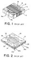
- the conventional magnetic sensor comprises an insulator case 11, a toroidal inductor 12 accommodated in the case 11, at least one detection coil 13 wound around the case 11.
- Two coils are usually provided in perpendicular to each other to detect X and Y components of the stray magnetic field.
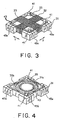
- the bobbin 11 further has a plurality of conductive pins 41 standing on the top surface thereof. Specifically, three pins 41 are placed in the vicinity of three corners of the top surface of the bobbin 31, respectively. These pins 41 serve to fasten end portions of the first and the second detection coils 32 and 33 wrapped thereto. In addition, the three pins 41 serve to position a frame member 43 illustrated in Fig. 4 to a predetermined location on the top surface of the bobbin 31.
- a low-melting-point solder 71 is previously adhered onto the surfaces of the conductive patterns 35 and the mating conductive patterns 61, and the printed circuit board 60 is then put onto the top surface of the bobbin 31. Thereafter, the bobbin 31 and the printed circuit board 60 with the solder between the conductive pattern 35 and the mating conductive pattern 61 are introduced into a reflow furnace kept at a temperature between 180 and 260 °C to electrically connect the conductive pattern 35 and the mating conductive pattern 61 to thereby form the toroidal excitation coil.
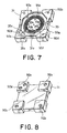
- the printed board 60 having the toroidal core 81 and the excitation coil is mounted on an insulator bobbin 83 having a ring-shaped groove 83a which receives therein the core 81 and the conductive wires 82.
- the first and the second detection coils (not shown) are wound around the bobbin 83 and the printed circuit board 60 mounted on the bobbin 83, in the similar manner shown at 32 and 33 in Fig. 3.
- the magnetic sensor is completed.
Landscapes
- Physics & Mathematics (AREA)
- Condensed Matter Physics & Semiconductors (AREA)
- General Physics & Mathematics (AREA)
- Measuring Magnetic Variables (AREA)
- Coils Or Transformers For Communication (AREA)
Claims (10)
- Magnetsensor mit:einem Spulenkörper (31, 83);einem in dem Spulenkörper (31, 83) angebrachten toroidalen Induktor, wobei der toroidale Induktor einen toroidalen Kern (36, 81) und eine um den toroidalen Kern (36, 81) gewickelte toroidale Erregerspule aufweist;mindestens einer um den Spulenkern (31, 83) gewickelten Detektorspule (32, 33), worin der Spulenkörper (31, 83) ein Spulenkörpergehäuse mit einer toroidalen Rille (31a), die den toroidalen Induktor aufnimmt, und eine Spulengehäuseabdeckung (55, 60), die mit dem Spulenkörpergehäuse verbunden ist, zum Abdecken der toroidalen Rille (31a) aufweist, wobei eines von dem Spulenkörpergehäuse und der Spulenkörperabdeckung ein Leitermuster (35, 61) aufweist;wobei das Leitermuster (35, 61) eine Mehrzahl von linearen Dünnfilmleitern aufweist, die sich radial so erstrecken, daß sie radiale innere Enden und äußere Enden haben und winkelmäßig voneinander beabstandet sind, wobei der toroidale Kern (36, 81) auf dem Leitungsmuster (35, 61) vorgesehen ist;einer Mehrzahl von Verbindungsleitern (51, 82), die sich radial über den toroidalen Kern (36) von einer Innenseite zu einer Außenseite des toroidalen Kernes (36, 81) erstrecken;wobei jeder der Verbindungsleiter (51, 82) ein inneres Ende aufweist, das mit dem radialen inneren Ende eines entsprechenden der linearen Dünnfilmleiter verbunden ist, und ein äußeres Ende aufweist, das mit dem radialen äußeren Ende eines benachbarten der linearen Dünnfilmleiter verbunden ist, so daß die Erregerspule mit dem Leitermuster (35, 61) und den Verbindungsleitern (51, 82) gebildet ist.
- Magnetsensor nach Anspruch 1, bei dem der Spulenkörper (31) mit zwei Detektorspulen (32, 33) versehen ist, die darauf in Richtungen senkrecht zueinander gewickelt sind.
- Magnetsensor nach Anspruch 1 oder 2, bei dem der Spulenkörper (31, 83) eine rechteckige Prismenform aufweist und/oder die toroidale Rille (31a) eine Kreisform oder eine polygonale Form aufweist.
- Magnetsensor nach einem der Ansprüche 1 bis 3, bei dem das Leitermuster (35) auf dem Spulenkörpergehäuse so gebildet ist, daß es sich radial von einer Innenseite zu einer Außenseite der toroidalen Rille erstreckt, die Verbindungsleiter (51) Drähte sind und die Spulenkörperabdeckung (55) ein Kunststoffharz ist, das auf dem Spulenkörpergehäuse zum Abdecken der Verbindungsleiter (51) des toroidalen Kernes (36) und des Leitungsmusters (35) zusammen vorgesehen ist.
- Magnetsensor nach einem der Ansprüche 1 bis 4, weiter mit einem Rahmenteil (43), das an dem Umfang der einen Oberfläche und außerhalb der Rille (31a) gebildet ist, so daß es nach oben von der einen Oberfläche vorsteht.
- Magnetsensor nach einem der Ansprüche 1 bis 3, bei dem das Leitungsmuster (35) auf dem Spulenkörpergehäuse so gebildet ist, daß es sich radial von einer Innenseite zu einer Außenseite der toroidalen Rille (31a) erstreckt, wobei die Spulenkörperabdekkung eine gedruckte Leiterplatte (60) mit den Verbindungsleitern als ein anderes Leitungsmuster (61), das darauf gebildet ist, ist.
- Magnetsensor nach einem der Ansprüche 1 bis 6, bei dem mindestens Innenseiten- und Bodenoberfläche der Rille (31a) mit einem Isolierteil bedeckt sind und/oder ein Material hoher Permeabilität auf dem Boden der Rille (35a) auf toroidale Weise zum Bilden des toroidalen Magnetkernes (36) abgeschieden ist und/oder der Magnetkern (36) mit einem Isolierfilm beschichtet ist, das ein organisches Material als eine Basiskomponente enthält und durch chemisches Dampfabscheiden abgeschieden ist zum Verhindern des elektrischen Kurzschlusses zwischen dem Leitungsmuster (35) und des Magnetkernes (36).
- Magnetsensor nach einem der Ansprüche 1 bis 7, bei dem das Leitungsmuster (35) mit einer Mehrzahl von Markierungen (93) versehen ist, die an gewünschten Positionen gebildet sind, zum Korrigieren einer Versetzung der Leitungsmuster (35).
- Magnetsensor nach einem der Ansprüche 1 bis 3, bei dem die Spulenkörperabdeckung eine gedruckte Leiterplatte (60) mit dem Leitungsmuster ist, wobei die Verbindungsleiter Verbindungsdrähte (61) sind, wodurch der toroidale Induktor fest auf der Spulenkörperabdeckung angebracht ist und in der toroidalen Rille (35a) des Spulenkörpergehäuses aufgenommen ist.
- Magnetsensor nach einem der Ansprüche 1 bis 9, bei dem der toroidale Magnetkern (36) aus einer dünnen Platte eines Materiales hoher Permeabilität gebildet ist und mit einem Isolierfilm beschichtet ist, der durch chemische Dampfabscheidung abgeschieden ist.
Applications Claiming Priority (9)
| Application Number | Priority Date | Filing Date | Title |
|---|---|---|---|
| JP215682/97 | 1997-07-25 | ||
| JP21568297 | 1997-07-25 | ||
| JP215680/97 | 1997-07-25 | ||
| JP21568297 | 1997-07-25 | ||
| JP21568097 | 1997-07-25 | ||
| JP21568097 | 1997-07-25 | ||
| JP8884898 | 1998-04-01 | ||
| JP88848/98 | 1998-04-01 | ||
| JP8884898 | 1998-04-01 |
Publications (2)
| Publication Number | Publication Date |
|---|---|
| EP0893699A1 EP0893699A1 (de) | 1999-01-27 |
| EP0893699B1 true EP0893699B1 (de) | 2001-12-19 |
Family
ID=27305924
Family Applications (1)
| Application Number | Title | Priority Date | Filing Date |
|---|---|---|---|
| EP98113905A Expired - Lifetime EP0893699B1 (de) | 1997-07-25 | 1998-07-24 | Magnetischer Fühler mit einer auf den Spulenkörper aufgebrachten lineare Dünnschichtleiterabschnitte aufweisenden Erregerspule mit darauf gewickelter Detektorspule |
Country Status (4)
| Country | Link |
|---|---|
| US (1) | US6181130B1 (de) |
| EP (1) | EP0893699B1 (de) |
| KR (1) | KR100421305B1 (de) |
| DE (1) | DE69803014T2 (de) |
Families Citing this family (43)
| Publication number | Priority date | Publication date | Assignee | Title |
|---|---|---|---|---|
| GB9821164D0 (en) * | 1998-09-30 | 1998-11-25 | Ward David | Measuring device |
| FR2805930B1 (fr) * | 2000-02-18 | 2005-12-30 | Aisin Seiki | Dispositif d'antenne en boucle |
| EP1260825A1 (de) * | 2001-05-25 | 2002-11-27 | Sentron Ag | Magnetfeldsensor |
| KR100432661B1 (ko) * | 2002-03-09 | 2004-05-22 | 삼성전기주식회사 | 인쇄회로기판 기술을 이용한 미약자계 감지용 센서 및 그제조방법 |
| KR100432662B1 (ko) * | 2002-03-09 | 2004-05-22 | 삼성전기주식회사 | 인쇄회로기판 기술을 이용한 미약자계 감지용 센서 및 그제조방법 |
| US6771066B2 (en) * | 2002-08-12 | 2004-08-03 | John B. Rippingale | Printed circuit fluxgate sensor for magnetic gradient detection device |
| US6734668B2 (en) * | 2002-10-02 | 2004-05-11 | Zetec, Inc. | Eddy current probe having diagonal magnetic fields alternating between posts at corners of orthogonal solenoid coils |
| US20050116801A1 (en) * | 2003-03-07 | 2005-06-02 | Proehl Gregory L. | Sensor coil and method of manufacturing same |
| DE10351119A1 (de) * | 2003-11-03 | 2005-06-02 | Neosid Pemetzrieder Gmbh & Co Kg | Induktives Miniatur-Bauelement, insbesondere Antenne |
| US20050093667A1 (en) * | 2003-11-03 | 2005-05-05 | Arnd Kilian | Three-dimensional inductive micro components |
| US7170382B1 (en) * | 2004-07-16 | 2007-01-30 | Altera Corporation | Design and fabrication of inductors on a semiconductor substrate |
| DE202004016751U1 (de) * | 2004-10-28 | 2005-03-03 | Pro-Micron Gmbh & Co. Kg Modular Systems | Transpondersystem |
| US7477128B2 (en) | 2005-09-22 | 2009-01-13 | Radial Electronics, Inc. | Magnetic components |
| US9754712B2 (en) | 2005-09-22 | 2017-09-05 | Radial Electronics, Inc. | Embedded magnetic components and methods |
| US10431367B2 (en) | 2005-09-22 | 2019-10-01 | Radial Electronics, Inc. | Method for gapping an embedded magnetic device |
| US10522279B2 (en) | 2005-09-22 | 2019-12-31 | Radial Electronics, Inc. | Embedded high voltage transformer components and methods |
| US10049803B2 (en) | 2005-09-22 | 2018-08-14 | Radial Electronics, Inc. | Arrayed embedded magnetic components and methods |
| JP3121577U (ja) * | 2006-03-02 | 2006-05-18 | 株式会社スマート | 偏心磁性体コイルシステム |
| DE102006025194A1 (de) * | 2006-05-29 | 2007-12-06 | Endress + Hauser Conducta Gesellschaft für Mess- und Regeltechnik mbH + Co. KG | Induktiver Leitfähigkeitssensor |
| JP4282734B1 (ja) * | 2007-12-20 | 2009-06-24 | 株式会社東芝 | 巻線部品、および電子機器 |
| US9754714B2 (en) | 2009-07-31 | 2017-09-05 | Radial Electronics, Inc. | Embedded magnetic components and methods |
| US8567046B2 (en) * | 2009-12-07 | 2013-10-29 | General Electric Company | Methods for making magnetic components |
| US9440378B2 (en) * | 2010-05-05 | 2016-09-13 | Tyco Electronics Corporation | Planar electronic device and method for manufacturing |
| CN102478646A (zh) * | 2010-11-29 | 2012-05-30 | 中国科学院合肥物质科学研究院 | 基于非晶磁芯线圈的磁敏传感器及其工作方法 |
| DE102012220022B4 (de) * | 2012-11-02 | 2014-09-25 | Festo Ag & Co. Kg | Verfahren zur Herstellung einer Spule und elektronisches Gerät |
| DE102012224101A1 (de) * | 2012-12-20 | 2014-06-26 | Continental Teves Ag & Co. Ohg | Verfahren zum Herstellen eines Messaufnehmers |
| KR20150025859A (ko) | 2013-08-30 | 2015-03-11 | 삼성전기주식회사 | 코일 부품 및 이를 이용하는 전자 모듈 |
| ES2548652B1 (es) * | 2014-04-16 | 2016-06-02 | Premo S.L. | Dispositivo para la formación de una bobina toroidal y método para la formación de una bobina toroidal |
| JP6278128B2 (ja) * | 2014-10-22 | 2018-02-14 | 株式会社村田製作所 | コイル部品 |
| EP3364429B1 (de) | 2017-02-16 | 2019-08-14 | Mitsubishi Electric R&D Centre Europe B.V. | Induktive anordnung |
| GB2567227A (en) | 2017-10-06 | 2019-04-10 | Heyday Integrated Circuits | Galvanically isolated gate drive circuit with power transfer |
| KR102010150B1 (ko) * | 2017-11-15 | 2019-08-12 | 충북대학교 산학협력단 | 자력 센서용 리본 자성체 보빈 구조체 |
| JP6872203B2 (ja) * | 2019-04-12 | 2021-05-19 | 士郎 嶋原 | レゾルバ |
| DE102020110898A1 (de) * | 2020-04-22 | 2021-10-28 | Neosid Pemetzrieder Gmbh & Co. Kg | Einteiliger Antennenkern |
| GB2595680B (en) * | 2020-06-02 | 2023-05-31 | Heyday Integrated Circuits Sas | Galvanically isolated package for switch drive circuit with power transfer |
| CN114188130B (zh) * | 2021-12-03 | 2024-06-18 | 苏州博思得电气有限公司 | 一种磁芯骨架、倍压组件、变压器及x射线高压发生器 |
| US12543574B2 (en) | 2023-04-14 | 2026-02-03 | Allegro Microsystems, Llc | Voltage-isolated integrated circuit packages |
| US12557668B2 (en) | 2023-04-27 | 2026-02-17 | Allegro Microsystems, Llc | High voltage integrated circuit packages with diagonalized lead configuration and method of making the same |
| US12672551B2 (en) | 2023-05-23 | 2026-06-30 | Allegro Microsystems, Llc | Transformer-based isolator with sense coil |
| US12267071B2 (en) | 2023-06-01 | 2025-04-01 | Allegro Microsystems, Llc | Desaturation circuit having temperature compensation |
| US12651691B2 (en) | 2023-07-11 | 2026-06-09 | Allegro Microsystems, Llc | Voltage-isolated integrated circuit packages with planar transformers |
| US12526012B1 (en) | 2024-09-26 | 2026-01-13 | Allegro Microsystems, Llc | Wireless power transmission with channel redundancy |
| US12640733B2 (en) | 2024-10-28 | 2026-05-26 | Allegro Microsystems, Llc | High-side gate drivers for fixed voltage rails |
Family Cites Families (14)
| Publication number | Priority date | Publication date | Assignee | Title |
|---|---|---|---|---|
| FR96237E (de) * | 1968-01-15 | 1972-05-19 | ||
| US4103267A (en) * | 1977-06-13 | 1978-07-25 | Burr-Brown Research Corporation | Hybrid transformer device |
| DE3434497A1 (de) | 1984-09-20 | 1986-03-20 | Vacuumschmelze Gmbh, 6450 Hanau | Induktives bauelement mit einem bewickelten ringbandkern |
| DE3519609A1 (de) * | 1985-05-31 | 1986-12-04 | Siemens AG, 1000 Berlin und 8000 München | Elektrische ringkernspule |
| DE3738455A1 (de) * | 1986-11-25 | 1988-06-01 | Landis & Gyr Ag | Anordnung zum messen eines flussarmen magnetfeldes |
| US4825166A (en) * | 1987-01-27 | 1989-04-25 | Sundstrand Data Control, Inc. | Bobbin for a magnetic sensor |
| JPS63142775U (de) * | 1987-03-10 | 1988-09-20 | ||
| DE4027994A1 (de) * | 1990-09-04 | 1992-03-05 | Gw Elektronik Gmbh | Hf-magnetspulenanordnung und verfahren zu ihrer herstellung |
| NL9002753A (nl) | 1990-12-14 | 1992-07-01 | Philips Nv | Inductieve inrichting met een ringvormige kern. |
| JPH04337610A (ja) | 1991-05-15 | 1992-11-25 | Fujitsu Ltd | インダクタンス部品 |
| US5199178A (en) * | 1991-10-23 | 1993-04-06 | Apac, Inc. | Thin film compass and method for manufacturing the same |
| JPH0661055A (ja) | 1992-08-04 | 1994-03-04 | Toyota Autom Loom Works Ltd | インダクタ |
| US5430613A (en) * | 1993-06-01 | 1995-07-04 | Eaton Corporation | Current transformer using a laminated toroidal core structure and a lead frame |
| JPH095083A (ja) * | 1995-06-16 | 1997-01-10 | Tokin Corp | 地磁気センサ及びその製造方法 |
-
1998
- 1998-07-24 DE DE69803014T patent/DE69803014T2/de not_active Expired - Fee Related
- 1998-07-24 EP EP98113905A patent/EP0893699B1/de not_active Expired - Lifetime
- 1998-07-24 US US09/122,524 patent/US6181130B1/en not_active Expired - Fee Related
- 1998-07-25 KR KR10-1998-0029997A patent/KR100421305B1/ko not_active Expired - Fee Related
Also Published As
| Publication number | Publication date |
|---|---|
| DE69803014D1 (de) | 2002-01-31 |
| KR19990014181A (ko) | 1999-02-25 |
| KR100421305B1 (ko) | 2004-04-17 |
| DE69803014T2 (de) | 2002-07-04 |
| US6181130B1 (en) | 2001-01-30 |
| EP0893699A1 (de) | 1999-01-27 |
Similar Documents
| Publication | Publication Date | Title |
|---|---|---|
| EP0893699A1 (de) | Magnetischer Fühler mit einer auf den Spulenkörper aufgebrachte lineare Dünnschichtleiterabschnitte aufweisenden Erregerspule mit darauf gewickelter Detektorspule | |
| AU666817B2 (en) | Current transformer using a laminated toroidal core structure and a lead frame | |
| US6160526A (en) | IC module and IC card | |
| EP1595158B1 (de) | Magnetfeldsensor und strommesser | |
| US3691497A (en) | Leadless microminiature inductance element with a closed magnetic circuit | |
| CN103026250B (zh) | 带扁平导电迹线的电磁线圈结构、磁芯和磁电角度传感器 | |
| US7084730B2 (en) | Chip coil and printed circuit board for the same | |
| US20080309443A1 (en) | Inductor and method for producing it | |
| WO2008008538A2 (en) | Self-leaded surface mount inductors and methods | |
| EP2960661B1 (de) | Modulares strommesssystem und verfahren zur herstellung eines modularen strommesssystems | |
| US20020094596A1 (en) | IC tag and method for production thereof | |
| US20220189679A1 (en) | Coil component | |
| US7639109B2 (en) | Sensor coil and method of manufacturing same | |
| EP1763044B1 (de) | Induktivität | |
| JP3574409B2 (ja) | 電流センサ及び電流測定回路 | |
| CN110619987B (zh) | 可调式贴片电感器及其制备方法 | |
| JP2985079B2 (ja) | 磁気センサ | |
| WO2003056347A1 (en) | Current sensor | |
| JP2729817B2 (ja) | インダクタンス素子 | |
| WO2010004491A1 (en) | Toroidal coil arrangement | |
| JP2000292295A (ja) | 密閉容器の内部圧力検出用センサ | |
| JP2003017347A (ja) | 電流センサ | |
| EP1185140B1 (de) | Elektroakustischer Wandler | |
| US11320464B2 (en) | Chip package | |
| JPH02150004A (ja) | インダクタンス素子 |
Legal Events
| Date | Code | Title | Description |
|---|---|---|---|
| PUAI | Public reference made under article 153(3) epc to a published international application that has entered the european phase |
Free format text: ORIGINAL CODE: 0009012 |
|
| AK | Designated contracting states |
Kind code of ref document: A1 Designated state(s): DE FR IT |
|
| AX | Request for extension of the european patent |
Free format text: AL;LT;LV;MK;RO;SI |
|
| 17P | Request for examination filed |
Effective date: 19990719 |
|
| AKX | Designation fees paid |
Free format text: DE FR IT |
|
| 17Q | First examination report despatched |
Effective date: 19991117 |
|
| GRAG | Despatch of communication of intention to grant |
Free format text: ORIGINAL CODE: EPIDOS AGRA |
|
| GRAG | Despatch of communication of intention to grant |
Free format text: ORIGINAL CODE: EPIDOS AGRA |
|
| GRAH | Despatch of communication of intention to grant a patent |
Free format text: ORIGINAL CODE: EPIDOS IGRA |
|
| GRAH | Despatch of communication of intention to grant a patent |
Free format text: ORIGINAL CODE: EPIDOS IGRA |
|
| GRAA | (expected) grant |
Free format text: ORIGINAL CODE: 0009210 |
|
| AK | Designated contracting states |
Kind code of ref document: B1 Designated state(s): DE FR IT |
|
| REF | Corresponds to: |
Ref document number: 69803014 Country of ref document: DE Date of ref document: 20020131 |
|
| PGFP | Annual fee paid to national office [announced via postgrant information from national office to epo] |
Ref country code: DE Payment date: 20020729 Year of fee payment: 5 |
|
| PGFP | Annual fee paid to national office [announced via postgrant information from national office to epo] |
Ref country code: FR Payment date: 20020730 Year of fee payment: 5 |
|
| RAP2 | Party data changed (patent owner data changed or rights of a patent transferred) |
Owner name: NEC TOKIN CORPORATION |
|
| PLBE | No opposition filed within time limit |
Free format text: ORIGINAL CODE: 0009261 |
|
| STAA | Information on the status of an ep patent application or granted ep patent |
Free format text: STATUS: NO OPPOSITION FILED WITHIN TIME LIMIT |
|
| 26N | No opposition filed | ||
| REG | Reference to a national code |
Ref country code: FR Ref legal event code: CD |
|
| PG25 | Lapsed in a contracting state [announced via postgrant information from national office to epo] |
Ref country code: DE Free format text: LAPSE BECAUSE OF NON-PAYMENT OF DUE FEES Effective date: 20040203 |
|
| PG25 | Lapsed in a contracting state [announced via postgrant information from national office to epo] |
Ref country code: FR Free format text: LAPSE BECAUSE OF NON-PAYMENT OF DUE FEES Effective date: 20040331 |
|
| REG | Reference to a national code |
Ref country code: FR Ref legal event code: ST |
|
| PG25 | Lapsed in a contracting state [announced via postgrant information from national office to epo] |
Ref country code: IT Free format text: LAPSE BECAUSE OF NON-PAYMENT OF DUE FEES Effective date: 20050724 |