EP0894518A2 - Antrieb für Reinigungs- und Verschiebevorrichtungen an Filterpressen - Google Patents
Antrieb für Reinigungs- und Verschiebevorrichtungen an Filterpressen Download PDFInfo
- Publication number
- EP0894518A2 EP0894518A2 EP98113291A EP98113291A EP0894518A2 EP 0894518 A2 EP0894518 A2 EP 0894518A2 EP 98113291 A EP98113291 A EP 98113291A EP 98113291 A EP98113291 A EP 98113291A EP 0894518 A2 EP0894518 A2 EP 0894518A2
- Authority
- EP
- European Patent Office
- Prior art keywords
- belt
- toothed
- drive
- drive according
- filter
- Prior art date
- Legal status (The legal status is an assumption and is not a legal conclusion. Google has not performed a legal analysis and makes no representation as to the accuracy of the status listed.)
- Granted
Links
Images


Classifications
-
- B—PERFORMING OPERATIONS; TRANSPORTING
- B01—PHYSICAL OR CHEMICAL PROCESSES OR APPARATUS IN GENERAL
- B01D—SEPARATION
- B01D25/00—Filters formed by clamping together several filtering elements or parts of such elements
- B01D25/12—Filter presses, i.e. of the plate or plate and frame type
- B01D25/172—Plate spreading means
-
- B—PERFORMING OPERATIONS; TRANSPORTING
- B01—PHYSICAL OR CHEMICAL PROCESSES OR APPARATUS IN GENERAL
- B01D—SEPARATION
- B01D25/00—Filters formed by clamping together several filtering elements or parts of such elements
- B01D25/32—Removal of the filter cakes
- B01D25/38—Removal of the filter cakes by moving parts, e.g. scrapers, contacting stationary filter elements sprayers
- B01D25/386—Nozzles
Definitions
- the invention relates to a drive for the cleaning and / or filter plate displacement device on filter presses according to the preamble of claim 1.
- DE 30 43 821 C2 shows a filter press with a cleaning trolley.
- the only figure shows the filter press with a head support on which the filter plates hang.
- the filter plate suspensions used for this are with the filter plate screwed and hung on the horizontal support by means of rollers.
- the cleaning trolley which can be moved back and forth on the head carrier carries both Washing device as well as a unit for moving the filter plates.
- DE 18 10 112 C2 shows a filter press with resting on side rails Filter plates.
- the shifting device provided with rollers, on the other hand, opens Guide rods above the filter plate package. Can be used to transport the filter plates different designs of the transport elements, the filter plates each grab on their top side. The carriage of the displacement device sits based on it Roll up directly on guide rods.
- DE 28 23 501 C1 shows in Figure 4 the transport device for the washing device.
- the car shown runs on a support located above the filter plates Roll.
- a chain or, for example, can also be carried on the carrier a rack or similar be arranged in which a directly driven by a motor Engages drive element.
- a filter press with two different drive systems for moving the Sliding device on horizontal beams and for the independent separation of the Filter plates show Figures 1 and 6 of DE 39 24 938 C1.
- the longitudinal movement of the The slide device is slid via a drive on drive rollers acts.
- the rollers themselves rest on horizontal rails.
- To postpone the A plate with a pawl and a star wheel are used for filter plates.
- the The chain runs over two gears, and the pawls on the chain each engage in the filter plate released by a star wheel, while the next through the star wheel is held back.
- the object of the present invention is to provide a drive for cleaning and / or Filter plate shifting devices so that an improved transmission of the Drive power is achieved with smooth running and low pollution.
- the measures according to the invention increase the area for transmitting the Traction through which the drive power can be transferred from the drive to the guides.
- Timing belts - are subject to a much gentler mode of operation than with State of the art.
- toothed pulleys come in Connection with a toothed belt to be used, the teeth of which mesh. Because of the use of an infinite toothed belt reduces the degree of contamination because the Toothed lock washers are almost completely covered.
- the drive according to the invention can also be used Use filter plate transport devices or combinations of both.
- the toothed disks have a guide for the Timing belt.
- the guide consists of a groove in the peripheral surface of the toothed lock washer in which the web of the toothed belt engages.
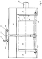
- FIG. 1 shows a filter press in a longitudinal side view with a support structure 10, which sits on side stands 12, 14. That depends on the stands 12, 14 several filter plates and between the top plate 16 and the end plate 18th tightened filter plate package 20.
- the filter plates of the piston-cylinder unit 26 are an exemplary embodiment tied together. The cleaning of the filter cloths takes place in certain cycles or at Need instead.
- a cleaning device 28 which cleans dry or wet can be used, which rests on the upper flange of one of the supports 30, 32 and which the lower tie rod 22 is guided and supported.
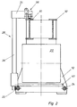
- the washing device shown for example in Figure 2 has an upper cross member 34 on which the drive 36 sits on the right and the vertical guide 38 for the left Wash bar 40 is attached.
- the wash bar rises and falls in each open one Filter chamber, where water remains under high pressure from the nozzles of the wash bar of the filter cake from the filter cloths.
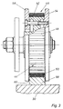
- the one intended for transporting the cleaning device along the carrier 30 Drive 36 transmits its drive power via a gear to the sprocket or Toothed washer 42.
- This toothed washer 42 which is directly coupled to the drive, in turn drives another toothed pulley 44, a toothed belt 46 being used as the drive means is coming.
- the infinite toothed belt wraps around the two toothed pulleys 42, 44, the Engage teeth 48 of toothed pulleys 42, 44 between teeth 50 of toothed belt 46.
- the stability of the toothed belt 46 is increased by embedded reinforcing wires 52.
- the entire drive unit which in this case moves the cleaning device 28, is held at the end of the cross member 34 in a carriage 53.
- the tooth lock washers are on attached to this sled by bolts and nuts.
- the toothed disc 44 is on on both long sides with discs 54, 56, which are also referred to as flanged wheels become. These disks 54, 56 protrude beyond the diameter of the toothed disks 42, 44 addition, so that there is a guide bar 58 between them in its lower region take up.
- the guide bar itself centers the toothed washer by contact of the disc flanks 60 on the long sides of the guide bar 58.
- toothed belt itself and the entire drive unit have its own side guide.
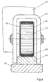
- tooth lock washers 42, 44 laterally with the disks 54, 56, also called flanged disks, and additionally spanned by a U-shaped bracket 62. Since the entire drive from Centering and guiding the bracket can be done separately Design the timing belt design more precisely or the guidance of the entire slide run more robust.
- the carrier (s) can also have U-shaped profiles open at the top carry. These profiles can, if they are made of metal, with a be elastic pad to avoid increased noise.
- FIG. 5 shows a further variant of the invention, in which the drive on one first sled sits.
- the gear connected to the drive wraps around you Timing belt in contact with the pulleys of a second slide. Due to the Belt length is a tension pulley 66 between the two pulleys of the second Arranged sled. The number of elements wrapped in the toothed belt increases the area for transmission of drive power (traction).
- FIG. 6 shows an embodiment of the toothed disks 42, 44 which consists of a Flange wheel with guidance on both sides.
- a larger dimensioned guide pulley 70 is provided, with its Is guided on the inside of the carrier 30 or on a support 72 on the carrier.
- a plastic is used for the support.
- the plastic is connected with the metallic carrier through an adhesive.
- the plastic pad is in the present case is rectangular. It surrounds the wearer on its top and lateral contact surface.
- FIG. 7 shows a special guidance of the toothed belt 46 on the toothed wheels 42, 44
- gear wheels have a groove 74 in their peripheral surface.
- the Web 76 of the toothed belt 46 guided.
- the toothed belt 46 engages.
- the toothed belt 46 has a profile on its tread 78 80.
Landscapes
- Chemical & Material Sciences (AREA)
- Chemical Kinetics & Catalysis (AREA)
- Devices For Conveying Motion By Means Of Endless Flexible Members (AREA)
- Filtration Of Liquid (AREA)
- Feeding Of Articles By Means Other Than Belts Or Rollers (AREA)
- Vehicle Body Suspensions (AREA)
- Filtering Of Dispersed Particles In Gases (AREA)
- Supporting Of Heads In Record-Carrier Devices (AREA)
Abstract
Description
- Figur 1
- Eine schematische Darstellung einer Filterpresse mit Waschvorrichtung in der Seitenansicht
- Figur 2
- Vertikaler Schnitt der Filterpresse mit Waschvorrichtung
- Figur 3
- Zahnriemenführung mit Aufbruch
- Figur 4
- Zahnriemenführung mit Bügel
- Figur 5
- Seitenansicht des Antriebs
- Figur 6
- Zahnriemenführung auf Kunststoffprofil
- Figur 7
- Zahnscheibe mit Führungsnut
Claims (9)
- Antrieb für eine auf einem horizontalen Träger (30, 32) aufgesetzte Reinigungs- und/oder Filterplattenverschiebevorrichtung an Filterpressen mit an horizontal angeordneten Trägern (30, 32) aufgehängten Filterplatten, die beim Filtriervorgang als Filterplattenpaket (20) dicht aneinander anliegen und nach dem Filtriervorgang vereinzelt werden,
dadurch gekennzeichnet, daß der Antrieb (36) mit einer ersten Scheibe (42) und über einen unendlichen Riemen (46) mit mindestens einer weiteren Scheibe (44) so verbunden ist, daß der Riemen (46) direkt auf einem Träger (30, 32) oder einer mit dem Träger verbundenen Auflage (58, 72) abrollt. - Antrieb nach Anspruch 1,
dadurch gekennzeichnet, daß der unendliche Riemen (46) ein Zahnriemen ist. - Antrieb nach Anspruch 1,
dadurch gekennzeichnet, daß die Scheiben (42, 44) mit einer Außenverzahnung (48) versehen sind, in die die Zähne (50) des Zahnriemens (46) eingreifen und der Zahnriemen (46) von ein- oder beidseitig über diese Zahnscheiben (42,44) überstehenden Scheiben (54, 56) begrenzt ist. - Antrieb nach Anspruch 1 oder 2,
dadurch gekennzeichnet, daß der Zahnriemen (46) auf einer auf den Träger (30, 32) aufgesetzten Führungsleiste (58) aufliegt, der mindestens einseitig eine als Anschlag dienende Scheibe (54) zugeordnet ist. - Antrieb nach einem der Ansprüche 1-3,
dadurch gekennzeichnet, daß die Zahnscheiben (42, 44) ein U-förmiger Bügel (62) umgreift, dessen Schenkelenden beidseitig an den Längsseiten der Führungsleiste (58) geführt sind. - Antrieb nach Anspruch 4,
dadurch gekennzeichnet, daß die Führungsleiste (58) aus einem nichtmetallischen Material besteht. - Antrieb nach einem der Ansprüche 1-6,
dadurch gekennzeichnet, daß die Scheiben (42, 44) auf ihrer Umfangsfläche eine Führung für den Riemen (46) aufweisen. - Antrieb nach Anspruch 7,
dadurch gekennzeichnet, daß die Scheiben (42, 44) eine zentrische Nut (74) aufweisen, in der der Steg (76) des Zahnriemens (46) geführt ist. - Antrieb nach Anspruch 8,
dadurch gekennzeichnet, daß die Scheiben (42, 44) beidseitig von der Nut eine Verzahnung aufweisen.
Applications Claiming Priority (2)
| Application Number | Priority Date | Filing Date | Title |
|---|---|---|---|
| DE19733486A DE19733486C1 (de) | 1997-08-01 | 1997-08-01 | Antrieb für Reinigungs- und Verschiebevorrichtungen an Filterpressen |
| DE19733486 | 1997-08-01 |
Publications (3)
| Publication Number | Publication Date |
|---|---|
| EP0894518A2 true EP0894518A2 (de) | 1999-02-03 |
| EP0894518A3 EP0894518A3 (de) | 1999-12-15 |
| EP0894518B1 EP0894518B1 (de) | 2004-03-24 |
Family
ID=7837814
Family Applications (1)
| Application Number | Title | Priority Date | Filing Date |
|---|---|---|---|
| EP98113291A Expired - Lifetime EP0894518B1 (de) | 1997-08-01 | 1998-07-16 | Antrieb für Reinigungs- und Verschiebevorrichtungen an Filterpressen |
Country Status (6)
| Country | Link |
|---|---|
| EP (1) | EP0894518B1 (de) |
| AT (1) | ATE262367T1 (de) |
| CZ (1) | CZ287819B6 (de) |
| DE (2) | DE19733486C1 (de) |
| ES (1) | ES2213858T3 (de) |
| SK (1) | SK282941B6 (de) |
Family Cites Families (6)
| Publication number | Priority date | Publication date | Assignee | Title |
|---|---|---|---|---|
| CH574752A5 (de) * | 1974-10-08 | 1976-04-30 | Von Roll Ag | |
| DE2823501C2 (de) * | 1978-05-30 | 1985-04-18 | Eberhard Hoesch & Söhne GmbH & Co, 5160 Düren | Plattenfilterpresse mit Steuereinrichtung für die Bewegung der Plattenverschiebevorrichtung und eines etwaigen Filtertuchwaschwagens |
| DE3043821C2 (de) * | 1980-11-20 | 1983-10-20 | Passavant-Werke AG & Co KG, 6209 Aarbergen | Plattenfilterpresse mit einem Reinigungswagen |
| DE8614127U1 (de) * | 1986-05-24 | 1987-09-24 | Häcker, Karl, 95659 Arzberg | Waschvorrichtung für Filtertücher |
| US4806239A (en) * | 1986-11-28 | 1989-02-21 | Envirotech Corporation | Apparatus for shifting filter plates in a filter press |
| DE3924938C1 (en) * | 1989-07-27 | 1991-01-03 | Erich Netzsch Gmbh & Co Holding Kg, 8672 Selb, De | Filter paper-removing device in filter press - comprises conveyance in which supports travel longitudinally, drive mechanism, restraining means, positioning means and stopping means |
-
1997
- 1997-08-01 DE DE19733486A patent/DE19733486C1/de not_active Expired - Fee Related
-
1998
- 1998-07-15 CZ CZ19982230A patent/CZ287819B6/cs not_active IP Right Cessation
- 1998-07-16 EP EP98113291A patent/EP0894518B1/de not_active Expired - Lifetime
- 1998-07-16 AT AT98113291T patent/ATE262367T1/de not_active IP Right Cessation
- 1998-07-16 DE DE59811040T patent/DE59811040D1/de not_active Expired - Fee Related
- 1998-07-16 ES ES98113291T patent/ES2213858T3/es not_active Expired - Lifetime
- 1998-07-17 SK SK982-98A patent/SK282941B6/sk unknown
Also Published As
| Publication number | Publication date |
|---|---|
| SK282941B6 (sk) | 2003-01-09 |
| ES2213858T3 (es) | 2004-09-01 |
| ATE262367T1 (de) | 2004-04-15 |
| CZ287819B6 (en) | 2001-02-14 |
| DE59811040D1 (de) | 2004-04-29 |
| SK98298A3 (en) | 1999-02-11 |
| EP0894518B1 (de) | 2004-03-24 |
| EP0894518A3 (de) | 1999-12-15 |
| CZ223098A3 (cs) | 1999-03-17 |
| DE19733486C1 (de) | 1998-09-24 |
Similar Documents
| Publication | Publication Date | Title |
|---|---|---|
| DE1925284C3 (de) | Kluppenkette für Spannkluppen in Spannrahmen | |
| EP0718020A1 (de) | Filterpresse zur Filtration von Suspensionen | |
| DE69010515T2 (de) | Transportband mit selbstfahrenden Lastträgern. | |
| CH630267A5 (de) | Verfahrvorrichtung fuer die auf zwei horizontalen fuehrungstraegern ruhenden filterplatten einer filterpresse. | |
| EP0541850A1 (de) | Kurvengängiges Plattenband | |
| DE2050503C3 (de) | Bandfilter für Flüssigkeiten | |
| DE2613149B2 (de) | Vorrichtung zum Reinigen von Förderbändern | |
| DE4243038A1 (de) | Horizontalbandfilter | |
| EP0894518B1 (de) | Antrieb für Reinigungs- und Verschiebevorrichtungen an Filterpressen | |
| DE3439647C2 (de) | Antriebsfahrwerk einer Elektro-Hängebahn mit automatischem Schaltgetriebe | |
| DE102008055482B4 (de) | Verfahren und Vorrichtung zum kontinuierlichen Aufbringen von Randprofilleisten auf einen Fördergurt einer Förderanlage | |
| DE2853952A1 (de) | Plattenfilterpresse mit vertikal ausgerichteten filterelementen und filtertuchtransport | |
| DE4121516A1 (de) | Foerderanlage mit einer tragschiene mit laufflaechen fuer angetriebene tragraeder von fahrzeugen | |
| DE3643662C1 (de) | Hub- und Senkstation fuer ein Schienenstueck | |
| DE3222989A1 (de) | Plattenfilter | |
| DE1965312B2 (de) | Antrieb fuer foerderketten mit lasttraegern | |
| DE3307488C2 (de) | Antriebsvorrichtung für eine Einschienen-Hängebahn bei Förderanlagen | |
| DE3502227C2 (de) | ||
| DE4235396C2 (de) | Seil-Fensterheber, insbesondere für Kraftfahrzeuge | |
| DE2021258A1 (de) | Vorrichtung zum Trocknen von Kleidern | |
| DE3924938C1 (en) | Filter paper-removing device in filter press - comprises conveyance in which supports travel longitudinally, drive mechanism, restraining means, positioning means and stopping means | |
| EP0848075A1 (de) | Vorrichtung zum Verfahren von Traversen für den Transport von zu verzinkenden Werkstücken an Tragschienen | |
| DE1217857B (de) | Steilfoerderer | |
| DE91653C (de) | ||
| DE3131594C2 (de) | Kluppenkettenbahn |
Legal Events
| Date | Code | Title | Description |
|---|---|---|---|
| PUAI | Public reference made under article 153(3) epc to a published international application that has entered the european phase |
Free format text: ORIGINAL CODE: 0009012 |
|
| AK | Designated contracting states |
Kind code of ref document: A2 Designated state(s): AT DE ES FR GB IT |
|
| AX | Request for extension of the european patent |
Free format text: AL;LT;LV;MK;RO;SI |
|
| PUAL | Search report despatched |
Free format text: ORIGINAL CODE: 0009013 |
|
| AK | Designated contracting states |
Kind code of ref document: A3 Designated state(s): AT BE CH CY DE DK ES FI FR GB GR IE IT LI LU MC NL PT SE |
|
| AX | Request for extension of the european patent |
Free format text: AL;LT;LV;MK;RO;SI |
|
| 17P | Request for examination filed |
Effective date: 19991208 |
|
| AKX | Designation fees paid |
Free format text: AT DE ES FR GB IT |
|
| 17Q | First examination report despatched |
Effective date: 20020927 |
|
| GRAP | Despatch of communication of intention to grant a patent |
Free format text: ORIGINAL CODE: EPIDOSNIGR1 |
|
| GRAS | Grant fee paid |
Free format text: ORIGINAL CODE: EPIDOSNIGR3 |
|
| GRAA | (expected) grant |
Free format text: ORIGINAL CODE: 0009210 |
|
| AK | Designated contracting states |
Kind code of ref document: B1 Designated state(s): AT DE ES FR GB IT |
|
| REG | Reference to a national code |
Ref country code: GB Ref legal event code: FG4D Free format text: NOT ENGLISH |
|
| REF | Corresponds to: |
Ref document number: 59811040 Country of ref document: DE Date of ref document: 20040429 Kind code of ref document: P |
|
| GBT | Gb: translation of ep patent filed (gb section 77(6)(a)/1977) |
Effective date: 20040423 |
|
| PGFP | Annual fee paid to national office [announced via postgrant information from national office to epo] |
Ref country code: GB Payment date: 20040621 Year of fee payment: 7 |
|
| PGFP | Annual fee paid to national office [announced via postgrant information from national office to epo] |
Ref country code: ES Payment date: 20040707 Year of fee payment: 7 |
|
| PGFP | Annual fee paid to national office [announced via postgrant information from national office to epo] |
Ref country code: FR Payment date: 20040721 Year of fee payment: 7 Ref country code: AT Payment date: 20040721 Year of fee payment: 7 |
|
| PGFP | Annual fee paid to national office [announced via postgrant information from national office to epo] |
Ref country code: DE Payment date: 20040809 Year of fee payment: 7 |
|
| REG | Reference to a national code |
Ref country code: ES Ref legal event code: FG2A Ref document number: 2213858 Country of ref document: ES Kind code of ref document: T3 |
|
| ET | Fr: translation filed | ||
| PLBE | No opposition filed within time limit |
Free format text: ORIGINAL CODE: 0009261 |
|
| STAA | Information on the status of an ep patent application or granted ep patent |
Free format text: STATUS: NO OPPOSITION FILED WITHIN TIME LIMIT |
|
| 26N | No opposition filed |
Effective date: 20041228 |
|
| PG25 | Lapsed in a contracting state [announced via postgrant information from national office to epo] |
Ref country code: IT Free format text: LAPSE BECAUSE OF NON-PAYMENT OF DUE FEES;WARNING: LAPSES OF ITALIAN PATENTS WITH EFFECTIVE DATE BEFORE 2007 MAY HAVE OCCURRED AT ANY TIME BEFORE 2007. THE CORRECT EFFECTIVE DATE MAY BE DIFFERENT FROM THE ONE RECORDED. Effective date: 20050716 Ref country code: GB Free format text: LAPSE BECAUSE OF NON-PAYMENT OF DUE FEES Effective date: 20050716 Ref country code: AT Free format text: LAPSE BECAUSE OF NON-PAYMENT OF DUE FEES Effective date: 20050716 |
|
| PG25 | Lapsed in a contracting state [announced via postgrant information from national office to epo] |
Ref country code: ES Free format text: LAPSE BECAUSE OF NON-PAYMENT OF DUE FEES Effective date: 20050718 |
|
| PG25 | Lapsed in a contracting state [announced via postgrant information from national office to epo] |
Ref country code: DE Free format text: LAPSE BECAUSE OF NON-PAYMENT OF DUE FEES Effective date: 20060201 |
|
| GBPC | Gb: european patent ceased through non-payment of renewal fee |
Effective date: 20050716 |
|
| PG25 | Lapsed in a contracting state [announced via postgrant information from national office to epo] |
Ref country code: FR Free format text: LAPSE BECAUSE OF NON-PAYMENT OF DUE FEES Effective date: 20060331 |
|
| REG | Reference to a national code |
Ref country code: FR Ref legal event code: ST Effective date: 20060331 |
|
| REG | Reference to a national code |
Ref country code: ES Ref legal event code: FD2A Effective date: 20050718 |