EP0894543A1 - Procédé et machine pour rincer et stériliser des bouteilles avec des buses mobiles entrant dans les bouteilles - Google Patents
Procédé et machine pour rincer et stériliser des bouteilles avec des buses mobiles entrant dans les bouteilles Download PDFInfo
- Publication number
- EP0894543A1 EP0894543A1 EP98830454A EP98830454A EP0894543A1 EP 0894543 A1 EP0894543 A1 EP 0894543A1 EP 98830454 A EP98830454 A EP 98830454A EP 98830454 A EP98830454 A EP 98830454A EP 0894543 A1 EP0894543 A1 EP 0894543A1
- Authority
- EP
- European Patent Office
- Prior art keywords
- nozzle
- bottle
- rinsing
- bottles
- sterilizing
- Prior art date
- Legal status (The legal status is an assumption and is not a legal conclusion. Google has not performed a legal analysis and makes no representation as to the accuracy of the status listed.)
- Granted
Links
- 230000001954 sterilising effect Effects 0.000 title claims abstract description 24
- 238000000034 method Methods 0.000 title claims abstract description 21
- 230000000149 penetrating effect Effects 0.000 title claims abstract description 15
- 239000007788 liquid Substances 0.000 claims abstract description 19
- 230000035515 penetration Effects 0.000 claims abstract description 9
- 238000002347 injection Methods 0.000 claims description 7
- 239000007924 injection Substances 0.000 claims description 7
- 230000010355 oscillation Effects 0.000 claims description 5
- 239000012530 fluid Substances 0.000 claims description 3
- 238000007664 blowing Methods 0.000 abstract description 2
- 238000004659 sterilization and disinfection Methods 0.000 abstract description 2
- 238000005406 washing Methods 0.000 description 15
- 239000000243 solution Substances 0.000 description 8
- 238000011109 contamination Methods 0.000 description 3
- 230000008878 coupling Effects 0.000 description 3
- 238000010168 coupling process Methods 0.000 description 3
- 238000005859 coupling reaction Methods 0.000 description 3
- 238000006073 displacement reaction Methods 0.000 description 2
- 230000007257 malfunction Effects 0.000 description 1
- XLYOFNOQVPJJNP-UHFFFAOYSA-N water Substances O XLYOFNOQVPJJNP-UHFFFAOYSA-N 0.000 description 1
Images


Classifications
-
- B—PERFORMING OPERATIONS; TRANSPORTING
- B08—CLEANING
- B08B—CLEANING IN GENERAL; PREVENTION OF FOULING IN GENERAL
- B08B9/00—Cleaning hollow articles by methods or apparatus specially adapted thereto
- B08B9/08—Cleaning containers, e.g. tanks
- B08B9/20—Cleaning containers, e.g. tanks by using apparatus into or on to which containers, e.g. bottles, jars, cans are brought
- B08B9/28—Cleaning containers, e.g. tanks by using apparatus into or on to which containers, e.g. bottles, jars, cans are brought the apparatus cleaning by splash, spray, or jet application, with or without soaking
- B08B9/30—Cleaning containers, e.g. tanks by using apparatus into or on to which containers, e.g. bottles, jars, cans are brought the apparatus cleaning by splash, spray, or jet application, with or without soaking and having conveyors
- B08B9/32—Rotating conveyors
-
- B—PERFORMING OPERATIONS; TRANSPORTING
- B08—CLEANING
- B08B—CLEANING IN GENERAL; PREVENTION OF FOULING IN GENERAL
- B08B9/00—Cleaning hollow articles by methods or apparatus specially adapted thereto
- B08B9/08—Cleaning containers, e.g. tanks
- B08B9/20—Cleaning containers, e.g. tanks by using apparatus into or on to which containers, e.g. bottles, jars, cans are brought
- B08B9/28—Cleaning containers, e.g. tanks by using apparatus into or on to which containers, e.g. bottles, jars, cans are brought the apparatus cleaning by splash, spray, or jet application, with or without soaking
- B08B9/34—Arrangements of conduits or nozzles
Definitions
- the present invention relates both to a method for rinsing or sterilizing bottles, and to a rinsing or sterilizing machine of the rotary type with movable nozzles penetrating inside the bottles.
- rotary rinsing machines essentially two types are known: a first type with a fixed nozzle, where the bottle is arranged so that its mouth is above the nozzle which remains substantially at the height of the opening in the neck, and a second type with a movable nozzle, where the nozzle penetrates inside the bottle by a given amount.
- the invention relates in particular to this latter type of rinsing machine.
- the machine in question consists of a machine with manual positioning of the bottles, where there is still contact between the external surface of the nozzle and the internal surface of the bottles with the drawbacks mentioned above.
- the machine in question consists of a rotary machine which requires a special and complex configuration of the nozzle in order to be able to strike a portion of the side walls of the bottle.
- Rotary rinsing machines with nozzles penetrating inside the bottle are known with reference to the patent WO 95 09699 A, in which penetration of the nozzle is performed by means of relative translation of the bottle or of the means retaining it, also during a step prior to complete tilting of bottle and nozzle.
- This solution also has the drawback of fairly long idle times since the treatment can in any case start only once tilting has occurred, when the connection to the liquid supply means is established. This connection is performed by means of contact, without the intervening arrangement of seals and therefore is unable to provide any guarantee as regards either reliability or absence of any risk of contamination.
- One object of the present invention is to eliminate the abovementioned drawbacks and provide a method and a machine for rinsing or sterilizing bottles of the rotary type with movable nozzles penetrating inside the bottles, in which the jet emerging from the nozzle strikes both the bottom and the side walls of the bottle, as a result of a relative movement of the nozzle and the bottle which does not cause contact between the two elements, guaranteeing hygienic conditions.
- the purpose of the machine according to the present invention is that of being able to orient the nozzle in one or more directions inclined with respect to the axis of the bottle.
- an object of the present invention is that of providing a method and a machine which eliminates the idle time, with treatment being started prior to the total tilting of the bottle.
- a further object of the present invention is that of dividing the step involving rotation of the bottle into a step independent of the nozzle, the latter remaining at a standstill in a substantially horizontal position, and a step integral with the nozzle with simultaneous penetration of the nozzle into the bottle. In this way the danger of dripping encountered in the other known solutions is avoided, since, along the section where the bottle is located underneath the nozzle, the axis of the nozzle itself remains in a horizontal position while the bottle returns into the vertical position.
- the present invention has a further advantage relating to the complete lack of possible contamination of the bottle, both because the nozzle does not touch the internal walls and because the supply duct is closed and sealed, along the section between the storage tank and the nozzle.
- the method for rinsing or sterilizing bottles according to the present invention which is characterized in that it envisages striking directly with a jet of rinsing or sterilizing liquid both the bottom and the side walls of the bottle.
- the side walls are struck by the jet by means of inclination of the nozzle itself or by means of inclination of the bottles with respect to the jet.
- a machine for rinsing or sterilizing bottles of the rotary type with movable nozzles penetrating inside the bottles which is characterized in that it comprises: means designed to cause rotation of the bottle independently of the nozzle until the coaxial condition of the bottle and nozzle is reached, means for relative fixing of the bottle and nozzle, which act when the coaxial condition of the two elements is reached, and means for causing rotation of the bottle integral with the nozzle, which generate at the same time the penetrating movement of the nozzle into the bottle.
- the configuration of the machine in question is characterized also by the presence of a plurality of nozzles which are positioned with their axes substantially horizontal radially with respect to the carousel.
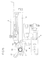
- 1 denotes a fixed frame of the machine, which supports a rotating platform or carousel 2 which is made to rotate in accordance with known techniques not illustrated.
- the carousel 2 supports a plurality of grippers 3 and a corresponding plurality of nozzles 4 which are connected to a washing liquid storage tank.
- the bottles reach the rinsing machine in the erect position by means of a conveyor of the screw or star type.
- Each gripper 3 is designed to grip a bottle 5 by the neck and tilt it through 180° so that the neck is directed downwards. To perform this tilting operation, the gripper 3 is supported by an arm 6 which is pivotably hinged at 7 with a fork member 8 integral with the carousel 2. For the rotation about the pivot 7, during the step where the gripper 3 and hence the bottle 5 move independently of the nozzle 4, each gripper has, integral with it, a fork member 9 which engages with a first actuating bar 10 of the known type which is circular and supported by the fixed frame 1. Closing and opening of the grippers is performed in accordance with a known technique by a cam 11 which is supported by the fixed frame 1 and with which a sliding piece 11a of the gripper of a known type interferes.
- Each nozzle 4 consists of an external cylinder 12 which is pivotably hinged at 7 via means which allow the gripper 3 to rotate independently of the nozzle 4, until the coaxial condition of the two elements is reached, and then render the gripper 3 and the nozzle 4 integral with each other during tilting and penetration of the nozzle into the bottle.
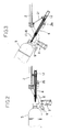
- the cylinder 12 forming the nozzle 4 has a longitudinal eyelet 13 through which one or more ducts 14 are able to pass (in the example illustrated two ducts 14 and 14a), said ducts connecting an external distribution block 15 to a sliding piece 16 inside the cylinder.
- the sliding block 16 has, fixed to it, two concentric pipes 17 and 18 which are spaced so as to form a first cannula, for injection of the washing fluid, inside the pipe 17 and a second injection cannula, in the interstice 19 between the two concentric pipes.
- the duct 14 is connected to the pipe 17, while the duct 14a is connected to the interstice 19.
- the distribution block 15 has, connected to it, by means of articulated headers 20, two rigid pipes 21 which engage, again by means of articulated headers 22, with a distribution block 23 which is integral with the carousel 2.
- Rigid pipes 24 supply the distributor 23 with suitable washing or sterilization liquids.
- the external cylinder 12 has, integral with it, a fork member 25 which embraces a second actuating bar 26 which is designed to cause integral rotation of the nozzle 4 and the gripper 3 about the same pivot 7.
- the external cylinder 12, the rotating pivot 7 and the actuating bar 26 form means for causing penetration of the nozzle into the bottle during the simultaneous rotation of bottle and nozzle, when the bottle has reached the position where it is coaxial with the nozzle itself.
- Figure 1 illustrates the step where the bottle in the erect position is gripped around the neck by the grippers 3 and the nozzle 4 is located in the rest position with its axis in a substantially horizontal position.
- the mouth of the bottle is located at a small distance from the nozzle and in this position it is possible to start injection of the washing liquid into the bottle.
- the second actuating bar 26 causes rotation of the external cylinder 12 of the nozzle about the pivot 7 together with rotation of the gripper.
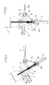
- the respective actuating bars 10 and 26 may be shaped so that the bottle and nozzle are not perfectly coaxial during their rotation, as shown in Figures 6, 7 and 8. In this way the jet of washing liquid may be advantageously directed into particular zones of the bottom of the bottle or onto the side walls thereof.
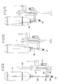
- nozzle 30 is able to perform a translatory movement vertically since it is integral with a slide 31 sliding along vertical pins 32.
- the slide is made to perform its translatory movement by means of a cam 33 of the known type.
- the nozzle 30 is supported by the slide 31 via a bracket 34 through which one or more ducts 35 supplying the washing fluid pass.
- connection of said ducts to the nozzle is effected by means of an articulated header 36 so as to allow the nozzle 30 to rotate and incline to the right or to the left with respect to the vertical axis.
- the nozzle may oscillate with respect to the axis of the bottle through a certain angle, said oscillation being imparted by the second actuating bar which is suitably shaped and having the purpose of reaching, with the jet of water, shaped zones of the bottom of the bottle (bottles with a petal-shaped bottom) or also the side walls of the bottle.
- the nozzle in the rest position, is situated so that it is substantially horizontal and, when the bottle also reaches this position, it is possible to start washing and to continue this washing operation during simultaneous rotation of bottle and nozzle, consequently increasing the hourly productivity of the machine for the same number of nozzles mounted on the carousel.
- a further advantage consists in the fact that the embodiment according to Figures 1 to 8 allows considerable penetration of the nozzle into the bottle with limited vertical dimensions of the gripper/nozzle assembly.
- a method for rinsing or sterilizing a bottle whereby both the bottom and the side walls of the bottle are struck directly with a jet of liquid.
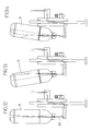
- This rinsing method is achieved by means of inclination of the jet with respect to the axis of the bottle, as illustrated in Figures 6, 7, 8, 9, 10 and 11 or by inclining the bottle with respect to the axis of the nozzle or the jet of liquid, as illustrated in Figures 12, 13 and 14.
- the machine will be provided with an actuating bar which is suitably shaped and allows inclination of the gripper and hence the bottle.
- a fork member 40 is fixed on the arm 6 and has, inserted between its prongs, a magnetic plate 41 arranged opposite a permanent magnet 42 integral with the cylinder 12.
- the function of the magnetic plate 41 and the permanent magnet 42 is that of coupling gripper and nozzle-carrying cylinder, as illustrated in Figure 16, so as to displace the nozzle from the vertical position into the horizontal position during the return movement of the gripper once washing has been performed. Displacement continues for a rotating movement of 90° until the nozzle-carrying cylinder comes into contact with the end-of-travel stopper 44.
Landscapes
- Engineering & Computer Science (AREA)
- Mechanical Engineering (AREA)
- Filling Of Jars Or Cans And Processes For Cleaning And Sealing Jars (AREA)
- Cleaning In General (AREA)
Applications Claiming Priority (2)
| Application Number | Priority Date | Filing Date | Title |
|---|---|---|---|
| ITPR970045 | 1997-08-01 | ||
| IT97PR000045A IT1294104B1 (it) | 1997-08-01 | 1997-08-01 | Procedimento per sciacquare o sterilizzare bottiglie e macchina sciacquatrice o sterilizzatrice del tipo rotativa ad ugelli mobili |
Publications (2)
| Publication Number | Publication Date |
|---|---|
| EP0894543A1 true EP0894543A1 (fr) | 1999-02-03 |
| EP0894543B1 EP0894543B1 (fr) | 2003-10-01 |
Family
ID=11396114
Family Applications (1)
| Application Number | Title | Priority Date | Filing Date |
|---|---|---|---|
| EP98830454A Expired - Lifetime EP0894543B1 (fr) | 1997-08-01 | 1998-07-27 | Procédé et machine pour rincer et stériliser des bouteilles avec des buses mobiles entrant dans les bouteilles |
Country Status (4)
| Country | Link |
|---|---|
| EP (1) | EP0894543B1 (fr) |
| DE (1) | DE69818578T2 (fr) |
| ES (1) | ES2205430T3 (fr) |
| IT (1) | IT1294104B1 (fr) |
Cited By (8)
| Publication number | Priority date | Publication date | Assignee | Title |
|---|---|---|---|---|
| FR2814095A1 (fr) * | 2000-09-18 | 2002-03-22 | Jean Paul Stentz | Procede de sterilisation de bouteilles et machine mettant en oeuvre ledit procede |
| WO2006136498A1 (fr) * | 2005-06-24 | 2006-12-28 | Sidel Participations | Installation produisant des bouteilles steriles par soufflage a partir de preformes sterilisees |
| ITTO20090837A1 (it) * | 2009-10-30 | 2011-04-30 | Sidel Spa Con Socio Unico | Macchina sciacquatrice per il trattamento di contenitori, in particolare bottiglie |
| EP2307184B1 (fr) | 2008-07-08 | 2016-06-29 | Krones AG | Installation pour la production de conteneurs avec un dispositif pour traiter une paroi extérieure des conteneurs avec un dispositif d'alimentation mobile et procédé associé |
| CN109158395A (zh) * | 2018-10-08 | 2019-01-08 | 广州达意隆包装机械股份有限公司 | 一种洗瓶机构及洗瓶机 |
| CN112386729A (zh) * | 2020-08-06 | 2021-02-23 | 曹宇 | 一种消毒机器人 |
| EP4403272A1 (fr) * | 2023-01-19 | 2024-07-24 | Krones Ag | Dispositif et procédé de rinçage de l'intérieur d'un récipient |
| EP4450177A1 (fr) | 2023-04-19 | 2024-10-23 | RIPRUP Company S.A. | Performance améliorée d'un distributeur de boissons |
Citations (5)
| Publication number | Priority date | Publication date | Assignee | Title |
|---|---|---|---|---|
| DE175369C (fr) * | ||||
| DE524004C (de) * | 1930-03-22 | 1931-05-01 | Schaeffler Maschinenfabrik Geb | Spritzrohr fuer Flaschenreinigungsmaschinen |
| EP0634230A1 (fr) * | 1993-07-12 | 1995-01-18 | PepsiCo, Inc. | Machine pour le lavage des bouteilles à haute vitesse et dispositif de pulvérisation |
| DE4330335A1 (de) * | 1993-09-08 | 1995-03-09 | Kronseder Maschf Krones | Spritzvorrichtung für Flaschenreinigungsmaschinen |
| WO1995009699A1 (fr) * | 1993-10-01 | 1995-04-13 | Etablissements Perrier | Dispositif pour deplacer un organe de traitement par rapport a un recipient, aux machines de nettoyage des bouteilles |
-
1997
- 1997-08-01 IT IT97PR000045A patent/IT1294104B1/it active IP Right Grant
-
1998
- 1998-07-27 EP EP98830454A patent/EP0894543B1/fr not_active Expired - Lifetime
- 1998-07-27 DE DE69818578T patent/DE69818578T2/de not_active Expired - Fee Related
- 1998-07-27 ES ES98830454T patent/ES2205430T3/es not_active Expired - Lifetime
Patent Citations (5)
| Publication number | Priority date | Publication date | Assignee | Title |
|---|---|---|---|---|
| DE175369C (fr) * | ||||
| DE524004C (de) * | 1930-03-22 | 1931-05-01 | Schaeffler Maschinenfabrik Geb | Spritzrohr fuer Flaschenreinigungsmaschinen |
| EP0634230A1 (fr) * | 1993-07-12 | 1995-01-18 | PepsiCo, Inc. | Machine pour le lavage des bouteilles à haute vitesse et dispositif de pulvérisation |
| DE4330335A1 (de) * | 1993-09-08 | 1995-03-09 | Kronseder Maschf Krones | Spritzvorrichtung für Flaschenreinigungsmaschinen |
| WO1995009699A1 (fr) * | 1993-10-01 | 1995-04-13 | Etablissements Perrier | Dispositif pour deplacer un organe de traitement par rapport a un recipient, aux machines de nettoyage des bouteilles |
Cited By (13)
| Publication number | Priority date | Publication date | Assignee | Title |
|---|---|---|---|---|
| FR2814095A1 (fr) * | 2000-09-18 | 2002-03-22 | Jean Paul Stentz | Procede de sterilisation de bouteilles et machine mettant en oeuvre ledit procede |
| JP4806018B2 (ja) * | 2005-06-24 | 2011-11-02 | スィデル・パルティスィパスィヨン | 殺菌消毒されたプリフォームをブロー成形することにより殺菌消毒されたボトルを製造するための設備 |
| FR2887525A1 (fr) * | 2005-06-24 | 2006-12-29 | Sidel Sas | Installation produisant des bouteilles steriles par soufflage a partir de preformes sterilisees |
| JP2008543619A (ja) * | 2005-06-24 | 2008-12-04 | スィデル・パルティスィパスィヨン | 殺菌消毒されたプリフォームをブロー成形することにより殺菌消毒されたボトルを製造するための設備 |
| US7806680B2 (en) | 2005-06-24 | 2010-10-05 | Sidel Participations | Installation for producing sterile bottles by blow molding sterilized preforms |
| WO2006136498A1 (fr) * | 2005-06-24 | 2006-12-28 | Sidel Participations | Installation produisant des bouteilles steriles par soufflage a partir de preformes sterilisees |
| EP2307184B1 (fr) | 2008-07-08 | 2016-06-29 | Krones AG | Installation pour la production de conteneurs avec un dispositif pour traiter une paroi extérieure des conteneurs avec un dispositif d'alimentation mobile et procédé associé |
| ITTO20090837A1 (it) * | 2009-10-30 | 2011-04-30 | Sidel Spa Con Socio Unico | Macchina sciacquatrice per il trattamento di contenitori, in particolare bottiglie |
| CN109158395A (zh) * | 2018-10-08 | 2019-01-08 | 广州达意隆包装机械股份有限公司 | 一种洗瓶机构及洗瓶机 |
| CN109158395B (zh) * | 2018-10-08 | 2024-03-19 | 广州达意隆包装机械股份有限公司 | 一种洗瓶机构及洗瓶机 |
| CN112386729A (zh) * | 2020-08-06 | 2021-02-23 | 曹宇 | 一种消毒机器人 |
| EP4403272A1 (fr) * | 2023-01-19 | 2024-07-24 | Krones Ag | Dispositif et procédé de rinçage de l'intérieur d'un récipient |
| EP4450177A1 (fr) | 2023-04-19 | 2024-10-23 | RIPRUP Company S.A. | Performance améliorée d'un distributeur de boissons |
Also Published As
| Publication number | Publication date |
|---|---|
| IT1294104B1 (it) | 1999-03-22 |
| DE69818578D1 (de) | 2003-11-06 |
| DE69818578T2 (de) | 2004-07-29 |
| ITPR970045A0 (it) | 1997-08-01 |
| EP0894543B1 (fr) | 2003-10-01 |
| ES2205430T3 (es) | 2004-05-01 |
| ITPR970045A1 (it) | 1999-02-01 |
Similar Documents
| Publication | Publication Date | Title |
|---|---|---|
| JP4733892B2 (ja) | 包装容器の滅菌方法および装置 | |
| EP2980007B1 (fr) | Procédé et dispositif de nettoyage d'un dispositif de remplissage | |
| EP0894543B1 (fr) | Procédé et machine pour rincer et stériliser des bouteilles avec des buses mobiles entrant dans les bouteilles | |
| RU2001123497A (ru) | Способ и устройство для стерилизации упаковочных контейнеров | |
| CN101505805B (zh) | 用于处理容器的方法和装置 | |
| JP5254134B2 (ja) | オープンジェット充填システム、方法および充填機 | |
| EP0758624B1 (fr) | Installation de remplissage stérile de bouteilles suivant un cycle continu | |
| KR20020073488A (ko) | 중공체의 전도장치 | |
| US5092356A (en) | Nozzle system to spray the insides of bottles | |
| JPH0752997A (ja) | 流体製品の計量フィードおよび包装用自動カルーセル機械 | |
| US7735297B2 (en) | Apparatus for capping bottles and a method for realising the cap | |
| JP2014055026A (ja) | 無菌充填用チャンバ内の滅菌方法及び装置 | |
| JP2014050479A (ja) | 無菌充填用チャンバ内の滅菌方法及び装置 | |
| US6564529B2 (en) | Bottle-capping system | |
| US10640350B2 (en) | Method for cleaning and/or disinfecting sealing elements, sealing machine, and sealing element | |
| JP2020128224A (ja) | 容器処理システム | |
| EP2748103B1 (fr) | Machine de remplissage permettant de désinfecter une ligne d'alimentation en boisson | |
| WO2020161759A1 (fr) | Machine et procédé de capsulage automatique de récipients, et ligne d'emballage comprenant ladite machine | |
| EP1497047B1 (fr) | Procédé permettant de laver l'interieur de contenants en plastique | |
| JPH10314691A (ja) | 内洗ノズルの洗浄装置 | |
| KR200216422Y1 (ko) | 물통 세척장치 | |
| PT1431436E (pt) | Máquina para tingir materiais têxteis | |
| CN120618994B (zh) | 一种配药罐用清洗装置 | |
| JP4554470B2 (ja) | 洗浄装置 | |
| CN121927875A (zh) | 一种用于瓶罐的连续传送式清洁机 |
Legal Events
| Date | Code | Title | Description |
|---|---|---|---|
| PUAI | Public reference made under article 153(3) epc to a published international application that has entered the european phase |
Free format text: ORIGINAL CODE: 0009012 |
|
| AK | Designated contracting states |
Kind code of ref document: A1 Designated state(s): DE ES FR IT |
|
| AX | Request for extension of the european patent |
Free format text: AL;LT;LV;MK;RO;SI |
|
| 17P | Request for examination filed |
Effective date: 19990505 |
|
| AKX | Designation fees paid |
Free format text: DE ES FR IT |
|
| 17Q | First examination report despatched |
Effective date: 20020411 |
|
| GRAH | Despatch of communication of intention to grant a patent |
Free format text: ORIGINAL CODE: EPIDOS IGRA |
|
| GRAH | Despatch of communication of intention to grant a patent |
Free format text: ORIGINAL CODE: EPIDOS IGRA |
|
| GRAA | (expected) grant |
Free format text: ORIGINAL CODE: 0009210 |
|
| AK | Designated contracting states |
Kind code of ref document: B1 Designated state(s): DE ES FR IT |
|
| REF | Corresponds to: |
Ref document number: 69818578 Country of ref document: DE Date of ref document: 20031106 Kind code of ref document: P |
|
| REG | Reference to a national code |
Ref country code: ES Ref legal event code: FG2A Ref document number: 2205430 Country of ref document: ES Kind code of ref document: T3 |
|
| ET | Fr: translation filed | ||
| PLBE | No opposition filed within time limit |
Free format text: ORIGINAL CODE: 0009261 |
|
| STAA | Information on the status of an ep patent application or granted ep patent |
Free format text: STATUS: NO OPPOSITION FILED WITHIN TIME LIMIT |
|
| 26N | No opposition filed |
Effective date: 20040702 |
|
| PGFP | Annual fee paid to national office [announced via postgrant information from national office to epo] |
Ref country code: ES Payment date: 20090805 Year of fee payment: 12 |
|
| PGFP | Annual fee paid to national office [announced via postgrant information from national office to epo] |
Ref country code: DE Payment date: 20090723 Year of fee payment: 12 |
|
| PG25 | Lapsed in a contracting state [announced via postgrant information from national office to epo] |
Ref country code: DE Free format text: LAPSE BECAUSE OF NON-PAYMENT OF DUE FEES Effective date: 20110201 |
|
| REG | Reference to a national code |
Ref country code: DE Ref legal event code: R119 Ref document number: 69818578 Country of ref document: DE Effective date: 20110201 |
|
| REG | Reference to a national code |
Ref country code: ES Ref legal event code: FD2A Effective date: 20110818 |
|
| PG25 | Lapsed in a contracting state [announced via postgrant information from national office to epo] |
Ref country code: ES Free format text: LAPSE BECAUSE OF NON-PAYMENT OF DUE FEES Effective date: 20100728 |
|
| PGFP | Annual fee paid to national office [announced via postgrant information from national office to epo] |
Ref country code: FR Payment date: 20110810 Year of fee payment: 14 |
|
| PGFP | Annual fee paid to national office [announced via postgrant information from national office to epo] |
Ref country code: IT Payment date: 20120628 Year of fee payment: 16 |
|
| REG | Reference to a national code |
Ref country code: FR Ref legal event code: ST Effective date: 20130329 |
|
| PG25 | Lapsed in a contracting state [announced via postgrant information from national office to epo] |
Ref country code: FR Free format text: LAPSE BECAUSE OF NON-PAYMENT OF DUE FEES Effective date: 20120731 |
|
| PG25 | Lapsed in a contracting state [announced via postgrant information from national office to epo] |
Ref country code: IT Free format text: LAPSE BECAUSE OF NON-PAYMENT OF DUE FEES Effective date: 20140727 |