EP0894680A1 - Procédé et dispositif d'assemblage de modules à coussin gonflable - Google Patents
Procédé et dispositif d'assemblage de modules à coussin gonflable Download PDFInfo
- Publication number
- EP0894680A1 EP0894680A1 EP98115250A EP98115250A EP0894680A1 EP 0894680 A1 EP0894680 A1 EP 0894680A1 EP 98115250 A EP98115250 A EP 98115250A EP 98115250 A EP98115250 A EP 98115250A EP 0894680 A1 EP0894680 A1 EP 0894680A1
- Authority
- EP
- European Patent Office
- Prior art keywords
- air bag
- base plate
- caulking
- portions
- pad cover
- Prior art date
- Legal status (The legal status is an assumption and is not a legal conclusion. Google has not performed a legal analysis and makes no representation as to the accuracy of the status listed.)
- Withdrawn
Links
- 238000000034 method Methods 0.000 title claims description 20
- 238000005452 bending Methods 0.000 claims abstract description 11
- 238000003825 pressing Methods 0.000 claims description 29
- 230000003405 preventing effect Effects 0.000 claims description 22
- 230000006872 improvement Effects 0.000 claims description 7
- 230000009467 reduction Effects 0.000 description 15
- 238000010276 construction Methods 0.000 description 8
- 238000003780 insertion Methods 0.000 description 6
- 230000037431 insertion Effects 0.000 description 6
- 230000002093 peripheral effect Effects 0.000 description 6
- 238000005304 joining Methods 0.000 description 5
- 230000006835 compression Effects 0.000 description 4
- 238000007906 compression Methods 0.000 description 4
- 230000009471 action Effects 0.000 description 3
- 238000002474 experimental method Methods 0.000 description 3
- 238000004519 manufacturing process Methods 0.000 description 3
- 230000001154 acute effect Effects 0.000 description 2
- 238000005520 cutting process Methods 0.000 description 2
- 230000004048 modification Effects 0.000 description 2
- 238000012986 modification Methods 0.000 description 2
- 230000004308 accommodation Effects 0.000 description 1
- 230000009977 dual effect Effects 0.000 description 1
- 230000000694 effects Effects 0.000 description 1
- 230000003287 optical effect Effects 0.000 description 1
- 230000008569 process Effects 0.000 description 1
- 238000012545 processing Methods 0.000 description 1
- 238000000275 quality assurance Methods 0.000 description 1
- 230000004044 response Effects 0.000 description 1
- 230000000717 retained effect Effects 0.000 description 1
- 230000000007 visual effect Effects 0.000 description 1
Images









Classifications
-
- B—PERFORMING OPERATIONS; TRANSPORTING
- B60—VEHICLES IN GENERAL
- B60R—VEHICLES, VEHICLE FITTINGS, OR VEHICLE PARTS, NOT OTHERWISE PROVIDED FOR
- B60R21/00—Arrangements or fittings on vehicles for protecting or preventing injuries to occupants or pedestrians in case of accidents or other traffic risks
- B60R21/02—Occupant safety arrangements or fittings, e.g. crash pads
- B60R21/16—Inflatable occupant restraints or confinements designed to inflate upon impact or impending impact, e.g. air bags
- B60R21/20—Arrangements for storing inflatable members in their non-use or deflated condition; Arrangement or mounting of air bag modules or components
- B60R21/217—Inflation fluid source retainers, e.g. reaction canisters; Connection of bags, covers, diffusers or inflation fluid sources therewith or together
-
- B—PERFORMING OPERATIONS; TRANSPORTING
- B23—MACHINE TOOLS; METAL-WORKING NOT OTHERWISE PROVIDED FOR
- B23P—METAL-WORKING NOT OTHERWISE PROVIDED FOR; COMBINED OPERATIONS; UNIVERSAL MACHINE TOOLS
- B23P11/00—Connecting or disconnecting metal parts or objects by metal-working techniques not otherwise provided for
Definitions
- This disclosure relates to an air bag apparatus mounted on a steering wheel, front instrument panel, front door trim or the like of an automobile, and more particularly to an apparatus for mounting and securing a pad cover onto and to a base plate mounted on a steering wheel, front instrument panel, front door trim or the like by way of a mounting plate or a like element.
- the present disclosure relates also to an assembling process for an air bag apparatus for an automobile, and more particularly to an assembling method and an assembling apparatus for fastening a pad cover and a base plate of an air bag apparatus to each other.
- the pad cover is generally referred to "module cover”, “receiving cover”, “lid”, “cover door” or “deployment door”, and is used as a case or housing for receiving an air bag or acted as cushioning.
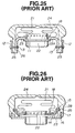
- FIG. 25 shows the mounting apparatus disclosed in Japanese Patent Laid-Open Application No. Heisei 4-27639.
- the mounting apparatus is applied to an air bag apparatus which includes an air bag 21 mounted on a mounting plate 23 and an air bag cover 24 which covers over the air bag 21.
- An upright portion 26 extends uprightly from a peripheral edge of a flat portion 23A of the mounting plate 23 on which the air bag 21, an inflator 22 and a retainer 18 (a ring-like element for securing the air bag 21 to the mounting plate 23) are mounted.
- a side circumferential wall 25 of the air bag cover 24 is contacted with an held against the upright portion 26 by a stiffening plate 12, and the elements are secured to each other by means of rivets 13 which extends through them.
- the mounting apparatus is called "rivet type" mounting apparatus.
- FIG. 26 shows the mounting apparatus disclosed in Japanese Patent Laid-Open Application No. Showa 55-110643.
- the mounting apparatus shown includes a mounting plate 23 to which a circumferential edge of a side circumferential wall 25 of an air bag cover 24, which covers over the circumference of an air bag 21, is snapped by means of a pawl plate 14 and a regulation wall 16 of the mounting plate 23.
- the pawl plate 14 has an arresting pawl 15 which is inserted in and engaged with an arresting groove 28 formed on an inner circumferential face of the side circumferential wall 25 of the air bag cover 24.
- the regulation wall 16 of the mounting plate 23 is inserted in an insertion groove 17 formed on a lower end face of the side circumferential wall 25 of the air bag cover 24.
- the mounting apparatus is called "snap-in type" mounting apparatus.
- One preferred aim is to provide an air bag apparatus of low weight which while able to avoid problems of the conventional air bag apparatus described above, is simple in structure and easy to mount a pad cover easily onto a base plate using a simple mounting apparatus for mounting a pad cover onto a base plate while assuring a sufficient strength.
- Another preferred aim is to provide an assembling method and an assembling apparatus by which an air bag apparatus can be assembled in accordance with a simple fastening method of fastening a pad cover onto a base plate and a base plate can be fastened to a pad cover readily with certainty in a short time to achieve improvement in assembling feasibility and productivity.
- pad cover terminal letting off preventing means may be provided on the side outer face portion or the side inner face portion of the base plate, or an arresting groove or an arresting hole for engaging with the letting off preventing means may be provided at the terminal portion of the pad cover.
- the pad cover terminal letting off preventing means is provided on the side outer face portion or the side inner face portion of the base plate or the arresting groove or the arresting hole for engaging with the letting off preventing means is provided at the terminal portion of the pad cover, it can be prevented fully that the pad cover, e.g. broken at a planned break line upon operation of the air bag, is blown off.
- an assembling method for an air bag apparatus wherein caulking portions formed by bending part of a base plate on which an air bag for protecting a driver of a vehicle upon collision of the vehicle and a gas generator for expanding the air bag are mounted hold leg portions of a pad cover in which the air bag and the gas generator are accommodated to secure the pad cover, constructed such that one or a plurality of ones of the caulking portions of the base plate to be caulked to the leg portions of the pad cover are deformed at a time to secure the base plate to the pad cover by means of a cam slide apparatus which is disposed around the air bag apparatus as a work for converting a pressing force in a vertical direction into a caulking force acting in a horizontal direction or acting in a circumferential direction around a fulcrum.
- an assembling apparatus for use with the assembling method is constructed such that, in order to deform one or a plurality of ones of the caulking portions of the base plate to be caulked to the leg portions of the pad cover at a time to secure the base plate to the pad cover, a cam slide apparatus for converting a pressing force in a vertical direction into a caulking force acting in a horizontal direction is disposed around the air bag apparatus as a work, and a pressing portion of a press apparatus is disposed above the cam slide apparatus.
- the assembling method for an air bag apparatus wherein caulking portions formed by bending part of a base plate on which an air bag for protecting a driver of a vehicle upon collision of the vehicle and a gas generator for expanding the air bag are mounted hold between leg portions of a pad cover in which the air bag and the gas generator are accommodated to secure the pad cover, is constructed such that one or a plurality of ones of the caulking portions of the base plate to be caulked to the leg portions of the pad cover are deformed at a time to secure the base plate to the pad cover by means of a cam slide apparatus which is disposed around the air bag apparatus as a work for converting a pressing force in a vertical direction into a caulking force acting in a horizontal direction or acting in a circumferential direction around a fulcrum and the assembling apparatus for use with the assembling method is constructed such that, in order to deform one or a plurality of ones of the caulking portions of the base plate to be caulked to the leg portions of the pad cover at a time to
- FIGS. 1 and 2 there is shown an air bag apparatus according to a first embodiment of the present invention.
- the air bag apparatus shown includes an air bag 1, a gas generator 2 for expanding or inflating the air bag 1, and a retainer 18 for mounting the air bag 1 on a base plate 3.
- the air bag 1, the gas generator 2, the retainer 18 and so forth are mounted on a flat plate portion 3A of the base plate 3.
- the gas generator 2 is inserted in and attached to a mounting hole 11 at the center of the flat plate portion 3A of the base plate 3.
- the air bag 1, the gas generator 2 and so forth are accommodated in a pad cover 4, and a plurality of terminal portion flanges 5A are provided at lower ends of a plurality of terminal portions 5 of the pad cover 4 such that they extend in parallel to the flat plate portion 3A of the base plate 3.
- the base plate 3 has a plurality of side inner face portions 6 formed by bending part of the same in a downward direction, that is, in the direction away from a passenger of a vehicle in which the air bag apparatus is incorporated, and a bottom portion 6A formed contiguously to each of the side inner face portions 6 by bending the same outwardly such that it extends in parallel to the flat plate portion 3A.
- a lower end of the terminal portion 5 of the pad cover 4 having the terminal portion flange 5A thereon is disposed along a side inner face portion 6 and a corresponding bottom portion 6A.
- the bottom portion 6A is further folded back in such a manner as to surround the terminal portion flange 5A to form a side outer face portion 7 so that the terminal portion 5 of the pad cover 4 is held between and secured to the side outer face portion 7 and the side inner face portion 6 thereby to form a caulking portion.
- Each of the side outer face portions 7 is further folded back to form a terminal holding portion 7A serving as letting off preventing means for preventing letting off of the terminal portion 5 of the pad cover 4 from the base plate 3.
- the terminal holding portion 7A may alternatively be formed as a riser element or elements 9A of FIG. 11 which will be hereinafter described.
- the pad cover and the base plate As mounting parts, it is only required to prepare the pad cover and the base plate. This can contribute very much to improvement in operability, reduction in part cost and reduction in weight. Further, since the terminal holding portions 7A as means for preventing letting off of the terminal portions 5 of the pad cover 4 are provided on the side outer face portions 7 to control upper portions of the terminal portion flanges 5A of the terminal portions 5 of the pad cover 4, such a situation that the pad cover 4 broken upon operation of the air bag 1 is blown off can be prevented effectively.
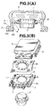
- FIGS. 3(A) and 3(B) show an air bag apparatus according to a second embodiment of the present invention.
- the air bag apparatus of the present embodiment is similar to the air bag apparatus of the first embodiment shown in FIG. 1 but is different in that the terminal holding portions 7A serving as means provided on the side outer face portions 7 for preventing letting off of the terminal portions 5 of the pad cover 4 are formed not by folding back the side outer face portions 7 as in the first embodiment but by bending the side outer face portions 7 in parallel to the bottom portions 6A of the base plate 3 in such a manner as to surround the terminal portion flanges 5A of the terminal portions 5 of the pad cover 4.
- the terminal holding portions 7A can be formed by simply bending the side outer face portions 7 in parallel to the bottom portions 6A of the base plate 3, and processing of the end portions of the side outer face portions 7 is comparatively easy.
- FIG. 3(B) is an exploded perspective view of the air bag apparatus according to the second embodiment of the present invention.
- FIG. 4 shows an air bag apparatus according to a third embodiment of the present invention. While the air bag apparatus of the present embodiment is similar in constructing the side outer face portion 7 and the terminal holding portion 7A of the base plate 3 to the air bag apparatus of the second embodiment of FIG. 3 described above, in the present embodiment, the terminal portion 5 of the pad cover 4 does not have the terminal portion flanges 5A provided in parallel to the flat plate portion 3A but is formed straight, and has arresting grooves 8 formed therein for engaging with the terminal holding portions 7A of the base plate 3.
- the terminal portions 5 of the pad cover 4 can be formed in a straight shape, which simplifies the structure.
- FIG. 5 shows an air bag apparatus according to a fourth preferred embodiment of the present invention.
- the air bag apparatus of the present embodiment is similar in shape of the base plate 3 and the terminal portions 5 of the pad cover 4 to the air bag apparatus of the second embodiment of FIG. 3 described above.
- the terminal holding portions 7A of the base plate 3 in the second embodiment are further bent upwardly to form accompanying portions 7B parallel to the side inner face portions 6.
- a divergent escape portion 7C may be formed at an upper end of an accompanying portion or portions 7B in order to prevent side wall faces of the terminal portions 5 of the pad cover 4 from being damaged by edges at the upper ends of the accompanying portions 7B upon caulking.
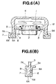
- FIGS. 6(A) and 6(B) show air bag apparatus according to a fifth embodiment of the present invention.
- the air bag apparatus of the present embodiment are similar to the air bag apparatus of the second embodiment of FIG. 3 described above, but is different in that arresting pawls 9 or riser pieces 9A serving as stopper means for preventing letting off of the terminal portions 5 of the pad cover 4 are provided on the side inner face portions 6 of the base plate 3.
- FIG. 6(A) shows the air bag apparatus wherein arresting pawls 9 or riser pieces 9A serving as letting off preventing means for the terminal portions 5 of the pad cover 4 are provided only on the inner sides of the terminal portion flanges 5A while FIG. 6(B) shows the air bag apparatus wherein arresting pawls 9 or riser pieces 9A serving as stopper means for the terminal portions 5 of the pad cover 4 are provided on the both sides of the terminal portion flanges 5A.
- the arresting pawls 9 or riser pieces 9A bite into side wall faces of the terminal portions 5 of the pad cover 4 to press the terminal portions 5 of the pad cover 4 strongly between the side outer face portions 7 and the terminal holding portions 7A of the base plate 3 and prevent letting off of the terminal portions 5 of the pad cover 4 with certainty.
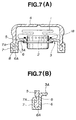
- FIGS. 7(A) and 7(B) show air bag apparatus according to a sixth embodiment of the present invention.
- the air bag apparatus of the present embodiment are similar to the air bag apparatus of the third embodiment of FIG. 4, and the terminal portions 5 of the pad cover 4 are formed straight in the present embodiment, i.e. without transverse projections from the envelope of the wall shape.
- the terminal holding portions 7A of the base plate 3 and the arresting grooves 8 formed in the terminal portions 5 of the pad cover 4 for receiving the terminal holding portions 7A are directed obliquely downwardly at an arcuate angle.
- FIG. 8(B) shows the arresting portion of the arresting hole 10 described above.
- a plurality of arresting holes 10 are perforated in each of the terminal portions 5 of the pad cover 4, and a plurality of side outer face portions 7 on which terminal holding portions 7A for engaging with the arresting holes 10 are provided are formed by folding back the base plate 3 by a plurality of times.
- the number, the width, the length, the shape and so forth of the terminal holding portions 7A can be set suitably in accordance with the shapes and the dimensions of different portions of the air bag.
- the arresting holes 10 perforated in the terminal portions 5 of the pad cover 4 are formed in parallel to the bottom portions 6A of the base plate 3. Accordingly, also the terminal holding portions 7A of the side outer face portions 7 are inserted in parallel to and engaged with the bottom portions 6A.
- FIGS. 9(A) to 9(E) show air bag apparatus according to an eighth embodiment of the present invention.
- the air bag apparatus of the present embodiment are modifications to the air bag apparatus of FIG. 8(C) in that the arresting hole 10 perforated in each of the terminal portions 5 of the pad cover 4 is formed in parallel to the bottom portions 6A of the base plate 3, and accordingly, a plurality of terminal holding portions 7A of the side outer face portions 7 formed by cutting and raising the side outer face portions 7 are inserted in parallel to and engaged with the bottom portions 6A.
- each of the terminal holding portions 7A is sufficiently inserted in the inside of an arresting hole 10 although such an arresting recessed portion 6B as is formed on the side inner face portion 6 of the base plate 3 of the air bag apparatus of FIG. 8(C) is not provided as shown in FIG. 9(B).
- FIG. 9(C) shows the air bag apparatus wherein a terminal holding portion pawl 7D is formed at an inner end portion of each of the terminal holding portions 7A by bending.
- the terminal holding portion pawl 7D is arrested with certainty at a stepped portion of an enlarged arresting hole 10A formed in the arresting hole 10 of the corresponding terminal portion 5 of the pad cover 4.
- FIG. 9(D) shows the air bag apparatus which is a modification to the air bag apparatus of FIG. 9(C) described above in that a plurality of arresting holes 10 are perforated in a zigzag pattern at upper and lower locations on each of the terminal portions 5 of the pad cover 4.
- a plurality of riser pieces formed on the side outer face portion 7 of the base plate 3 by cutting and raising the side outer face portion 7 in a zigzag pattern in the opposite directions to each other are adopted as the terminal holding portions 7A to be arrested by the arresting holes 10.
- dual letting off preventing means is formed.
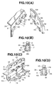
- FIGS. 10 (A) to 10(D) show air bag apparatus according to a ninth embodiment of the present invention. While the air bag apparatus of the present embodiment are similar to the air bag apparatus of FIGS. 8(A) to 8(C) and 9(A) to 9(D), the air bag apparatus of the present embodiment are different from them in that, similarly as in the air bag apparatus shown in FIGS. 3(A) and 3(B), 5, and 6(A) and 6(B), a terminal portion flange 5A is formed at a terminal portion 5 of the pad cover 4, and a plurality of such terminal portion flanges 5A are provided intermittently such that they extend inwardly.
- elongated portions constituting the side outer face portions 7 and the terminal holding portions 7A which serve as caulking portions and tongue pieces 6C are formed alternately, and tongue piece insertion holes 5B for receiving the tongue pieces 6C are perforated in the vertical direction through the terminal portion flanges 5A.
- the entire pad cover 4 can be secured firmly to the base plate 3 by, in addition to the letting off preventing action provided by engagement of the terminal holding portions 7A with the arresting holes 10, another letting off preventing action provided by engagement between the tongue pieces 6C and the tongue piece insertion holes 5B.
- a plurality of terminal portion flange insertion holes 7E are perforated in the side outer face portions 7 serving as caulking portions of the base plate 3, and the terminal holding portions 7A are formed intermittently at upper ends of the side outer face portions 7. Further, a plurality of terminal portion flanges 5A are formed intermittently toward the outer side on each of the terminal portions 5 of the pad cover 4, and a plurality of arresting hole 10 are perforated in each of the terminal portions 5.
- the terminal portion flanges 5A are inserted in and arrested by the terminal portion flange insertion holes 7E, and the terminal holding portions 7A are inserted in and arrested by the arresting holes 10.
- FIG. 11 shows an air bag apparatus according to a tenth embodiment of the present invention.
- the pad cover 4 has the terminal portions 5 which are each formed straight or in a little tapered profile such that it has a greater thickness at a lower portion thereof, and side outer face portions 7 of the base plate 3 are caulked such that they extend along the side wall faces of the terminal portions 5 of the pad cover 4.
- the air bag apparatus has a simplified structure.
- a riser piece 9A may be provided on each of flattened side outer face portions 7 as shown on the right side in FIG. 11 in order to enhance the letting off preventing action.
- FIG. 12 shows an air bag apparatus according to an eleventh embodiment of the present invention.
- the pad cover 4 has the terminal portions 5 similar to those in the eighth embodiment of FIG. 11.
- terminal holding portions 7A parallel to the flat plate portion 3A are opposed to the terminal portions 5 of the pad cover 4, and the terminal portions 5 of the pad cover 4 are held strongly by an edge action of corner portions of the terminal holding portions 7A.
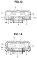
- FIG. 13 shows an air bag apparatus according to a twelfth embodiment of the present invention.
- the side inner face portions 6 of the base plate 3 are bent upwardly, that is, toward the drive and then folded back downwardly, whereafter they are bent outwardly in parallel to the flat plate portion 3A of the base plate 3 to form the bottom portions 6A, and then bent upwardly to form the side outer face portions 7.
- the side outer face portions 7 of the base plate 3 are caulked such that they are provided along and pressed against the terminal portions 5 of the pad cover 4 which are formed substantially straight or in a little tapered profile such that each of them has a greater thickness at a lower portion thereof.
- the pad cover 4 can be formed with a maximum volume.
- a riser piece 9A serving as letting off preventing means may be provided on each of the side outer face portions 7 as shown on the right side of FIG. 13.
- FIG. 14 shows an air bag apparatus according to a thirteenth embodiment of the present invention.
- the position of the flat plate portion 3A of the base plate 3 can be relatively displaced downwardly to the position of the lower ends of the terminal portions 5 of the pad cover 4 to assure a maximum volume for the pad cover 4, the air bag apparatus has a simplified structure.
- the side inner face portions 6 of the pad cover 4 are first bent upwardly, that is, toward the driver and then bent outwardly in parallel to the flat plate portion 3A of the base plate 3 so that they are inserted into the arresting holes 10 perforated in the terminal portions 5 of the pad cover 4, and are further bent downwardly to form the side outer face portions 7.
- the portions of the base plate to which the pad cover is secured are open first, and the pad cover is secured only by deforming, after the base plate is combined with the pad cover, the base plate side into a predetermined shape to caulk the base plate to the pad cover, or in other words, only by deforming the base plate.
- the base plate may be secured to the pad cover by means of riveting or the like in addition to caulking or by means of a structure wherein the base plate is fitted in a groove formed in the pad cover without employing caulking.
- the air bag apparatus which at least includes an air bag for protecting a driver of a vehicle upon collision of the vehicle, a base plate for mounting thereon a gas generator for inflating the air bag, and a pad cover secured to the base plate for accommodating the air bag and the gas inflator therein, is constructed such that part of the base plate is deformed into a predetermined shape to secure the pad cover to the base plate, and preferably, part of the base plate is bent to form a side inner face portion and is further folded back to form a side outer face portion and a terminal portion of the pad cover is held between and secured by the side outer face portion and the side inner face portion of the base plate, by deforming part of the base plate into the predetermined shape, the caulking portion is formed. Consequently, the terminal portion of the pad cover can be mounted on the base plate with a sufficient strength with a simple structure.
- the position of the base plate can be relatively displaced downwardly, and the pad cover can have a maximum volume.
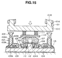
- FIGS. 15 and 16 illustrate a method of assembling the air bag apparatus as described above and also show an embodiment of an assembling apparatus for the air bag apparatus.
- FIG. 16 is a plan view showing a press apparatus 101 with a pressing portion thereof removed.
- FIG. 15 which shows a sectional view taken along line A-A of FIG. 16, an air bag apparatus as a work wherein leg portions 107A of a pad cover 107 for accommodating an air bag 114 and so forth therein are temporarily placed on caulking portions 106 of a base plate 108 on which the air bag 114 and so forth are mounted is placed onto a work receiving table 104A provided substantially at a central portion of a press base 104.
- the air bag apparatus urges a plurality of protruding pins 112 downwardly.
- the protruding pins 112 are embedded in the work receiving table 104A and have biasing springs 113 for resiliently projecting the air bag apparatus as a work to take out the same after assembly.
- pairs of press blocks 103 of cam slide apparatus 102 each of which is constituted from press blocks 103 disposed on the press base 104 and slidably movable in a vertical direction and a caulking block 105 which is located, at a cam face 105A thereof, adjacent cam faces 103A of the press blocks 103 and slidably movable in a horizontal direction, downwardly as indicated by an arrow mark. Consequently, the cam faces 103A which are inclined at lower ends thereof act upon the cam faces 105A of the caulking blocks 105 to slidably move the caulking blocks 105 in horizontal directions as indicated by arrow marks to deform the caulking portions 106 of the base plate 108. Consequently, the caulking portions 106 of the base plate 108 are fastened and secured firmly to the leg portions 107A of the pad cover 107.
- the pressing portion 101C is retracted upwardly, whereupon the caulking blocks 105 and the press blocks 103 are returned to their original positions by return springs 109 built in the caulking blocks 105.
- the air bag apparatus as a unit is resiliently projected upwardly by the protruding pins 112 having the biasing springs 113 embedded in the work receiving table 104A, and consequently, the air bag apparatus can be taken out readily.
- Each of the cam slide apparatus 102 for converting the pressing forces in vertical directions into caulking forces in horizontal directions includes, as shown in a plan view in FIG. 16, an outer frame 102A and an inner frame 102B disposed around the air bag apparatus as a work and each having a substantially square shape.
- the outer frame 102A and the inner frame 102B are secured at corner portions thereof for adjustment in fixed positions thereof by fixing angles 116.
- the outer frame 102A and the inner frame 102B have dimensions which can be adjusted in accordance with the magnitude of the work.
- holding angles 115 for holding the outer frames 102A from the outside have an elongated hole 115A formed therein so that the amount of the adjustment can be absorbed.
- a number of blocks each including a pair of press blocks 103 and a caulking block 105 for converting the pressing force in a vertical direction into a caulking force in a horizontal direction are disposed in accordance with the number and the positions of the caulking portions 106 of the base plate 108 to be caulked around the work on the square cam slide apparatus 102 such that one or a plurality of ones of the caulking portions 106 are deformed at a time to secure the work.
- FIG. 17 shows an air bag assembly apparatus according to a fifteenth embodiment of the present invention.
- the air bag assembly apparatus is characterized in that a holding piece 105B for suppressing inadvertent upward movement of a caulking portion 106 of the base plate 108 upon caulking is provided at an end of each of the caulking blocks 105 of the cam slide apparatus 102, and a holding face 105C of a shape which extends along a locus of deformation of an upper end of the caulking portion 106 is formed on a front face of the holding piece 105B.
- an arresting pin 117 which is moved, when the base plate 108 of the air bag apparatus as a work is placed properly on protruding pins 112 embedded in the work receiving table 104A, by downward movement of the protruding pins 112 by a cam face or the like and arrested by pin holes 108A (mounting holes used to mount the air bag apparatus onto a steering wheel or the like of an automobile) or the like of the base plate 108 is embedded, then inadvertent upward movement of the base plate 108 upon caulking at the caulking blocks 105 can be suppressed with certainty only by placing the work properly onto the work receiving table 104A.
- Removal of the arresting pin 117 from the pin hole 108A is allowed by accommodation of the arresting pin 117 into a cam groove 112B of the corresponding protruding pin 112 as a result of upward movement of an armature 112A attracted by a solenoid 119 which is provided at a lower portion of the work receiving table 104A and energized in response to movement of the pressing portion 101C which is retraced upwardly upon completion of the caulking step.
- FIG. 18 shows an air bag assembly apparatus according to a sixteenth embodiment of the present invention.
- the air bag apparatus is characterized in that a stiffening plate 120 having a fulcrum 104B on the press base 104 is disposed between an end of each of the caulking blocks 105 of the cam slide apparatus 102 and a corresponding caulking portion 106 of the base plate 108 as a work, and the end of the caulking block 105 is formed as an arcuate face so that it may not damage the stiffening plate 120.
- the stiffening plate 120 is held in a little inclined relationship at an original position by a holding spring 121 and is tilted by protrusion of the caulking block 105 pulling the holding spring 121 to perform a caulking operation along the caulking portion 106 of the base plate 108.
- An upper end of the stiffening plate 120 may be bent a little in order to suppress upward inadvertent movement of the caulking portion 106.
- the stiffening plate 120 is returned to the original position by the holding spring 121.
- the inclined stiffening plates 120 at their original position effect, if they are disposed around the air bag apparatus as a work, a positioning action upon proper placement of the air bag apparatus onto the work receiving table 104A.
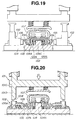
- FIG. 19 shows an air bag assembly apparatus according to a seventeenth embodiment of the present invention.
- the air bag assembly apparatus is characterized in that the work receiving table 104A is disposed for movement in a horizontal direction on the press base 104 with a balancing spring 122 interposed therebetween.
- the work receiving table 104A is formed so as to have a tray-shaped cross section and is disposed in such a manner as to cover over a pressing portion 104C provided on the press base 104 so that it may be moved leftwardly and rightwardly in horizontal directions (when necessary, also in forward and backward directions).
- a pair of balancing springs 122A and 122B are disposed between the opposite sides of the pressing portion 104C and the inner side of the work receiving table 104A.
- the work receiving table 104A is moved either leftwardly or rightwardly by an action of the balancing spring 122 to absorb the difference in dimension caused by the error in deformation so that the left and right caulking portions 106 can be caulked equally.
- FIG. 20 shows an air bag assembly apparatus according to an eighteenth embodiment of the present invention.
- each of the cam slide apparatus 102 for converting the pressing force in a vertical direction into a caulking force in a horizontal direction is constituted from a pair of press blocks 103 mounted for sliding movement in a vertical direction and a caulking block 105 which is provided adjacent the press blocks 103 by way of a cam face thereof and is slidably moved in a horizontal direction while the press blocks 103 are components of the cam slide apparatus 102
- the air bag assembly apparatus is characterized in that the press blocks 103 are formed integrally as press blocks 101D at lower portions of the pressing portion 101C of the press apparatus 101.
- a cam face 101E is formed at a lower end portion of each of the press block 101D, and the press blocks 101D are disposed in such a positional relationship that the cam faces 101E conform to cam faces 105A of the caulking blocks 105 of the corresponding cam slide apparatus 102 which are slidably moved in a horizontal direction.
- the press blocks 101D are secured to the pressing portion 101C of the press apparatus 101 such that the positions thereof can be adjusted so that they may correspond to the positions of the cam slide apparatus 102 which are adjusted in accordance with the size of the work.
- FIG. 21 shows an air bag assembly apparatus according to a nineteenth embodiment of the present invention.
- the air bag apparatus is constructed such that, similarly as in the fifteenth embodiment shown in FIG. 17, when a caulking portion 106 of the base plate 108 is pushed to be deformed in a horizontal direction by a corresponding caulking block 105, it is prevented that the caulking portion 106 is inadvertently moved upwardly. While it is similar as in the fifteenth embodiment described above that the holding pieces 105B are provided at the ends of the caulking blocks 105 of the cam slide apparatus 102, in the present embodiment, the caulking blocks 105 are disposed in an inclined relationship in the cam slide apparatus 102 such that each of them may be slidably moved in a little obliquely downward direction.
- the pressing force in a vertical direction of each of the press blocks 103 pressed by the press apparatus is converted into a little obliquely downwardly acting caulking force of a caulking block 105 by way of the cam faces 103A and the cam face 105A, and consequently, the holding piece 105B at the end of each of the caulking blocks 105 prevents inadvertent upward movement of the corresponding caulking portion 106 effectively.
- FIG. 22 shows an air bag assembly apparatus according to a twentieth embodiment of the present invention.
- a pair of pressure gauges 123A and 123B which indicate, when the base plate 108 of the air bag apparatus as a work is placed properly such that it is urged upwardly by the protruding pins 112 embedded in the work receiving table 104A and having the urging springs 113, predetermined numerical values depending upon the balance with the biasing springs 113 are provided at lower portions of the caulking portions 106 on the press base 104.
- Reference characters 124A and 124B denote pressure gauges which indicate pressure signals from the pressure gauges 123A and 123B, respectively.
- pressure gauges 123A and 123B may be replaced by suitable sensors such as optical sensors or the like for detecting that the base plate 108 as a work has been set properly onto the work receiving table 104A.
- FIG. 23 shows an air bag assembly apparatus according to a twenty-first embodiment of the present invention.
- the base plate 108 of the air bag apparatus as a work is detected whether or not the base plate 108 of the air bag apparatus as a work has been set properly to the work receiving table 104A.
- a pair of conductive electrodes 125A and 125B provided at lower portions of the caulking portions 106 on the press base 104 are both put into a conducting state with the conductive base plate 108 so that a power source circuit for an indicator lamp is closed to light an indicator lamp 127.
- Reference numeral 126 denotes a power source.
- the electrodes 125A and 125B may be replaced by pressure switches which are put into a conducting state to close the circuit for an indicator lamp to light the indicator lamp 127 when the base plate 108 is placed properly onto the press base 104.
- FIG. 24 shows an air bag assembly apparatus according to a twenty-second embodiment of the present invention.
- the present embodiment is applied to an air bag apparatus for the assistant driver's seat.
- the air bag apparatus as a work wherein the leg portions 107A of the pad cover 107 for accommodating the air bag 114 for the assistant driver's seat and so forth therein and the terminal portions 114A of the air bag 114 are temporarily placed on the caulking portions 106 of the base plate 108 for the assistant driver's seat on which the air bag 114, an inflator 128 and so forth are mounted is placed onto the work receiving table 104D provided substantially at the central portion of the press base 104.
- the air bag apparatus urges the protruding pins 112, which are embedded in the work receiving table 104D and have the biasing springs 113 for projecting the air bag apparatus so as to allow removal of the same after assembly, downwardly.
- Description of a caulking step after that is omitted herein since it is similar to that in the embodiments described.
- the caulking portions 106 of the base plate 108 are caulked together with the terminal portions 114A of the air bag 114 dragged in at least to a location below the leg portions 107A of the pad cover 107 to fasten the air bag, further save in power of the assembling step can be realized.
- the present method of caulking the caulking portions 106 of the base plate 108 together with the terminal portions 114A of the air bag 114 dragged in at least to the location below the leg portions 107A of the pad cover 107 to secure the caulking portions 106 of the base plate 108 to the leg portions 107A of the pad cover 107 can naturally be adopted to the air bag apparatus of any of the embodiments described hereinabove.
- terminal portions 114A of the air bag 114 dragged in at least to the location below the leg portions 107A of the pad cover 107 may be further dragged back to a location outwardly of the leg portions 107A of the pad cover 107.
- the strokes of the press apparatus and the cam slide parts were able to be monitored in units of 0.1 mm to 0.5 mm, and it was also possible to conform a degree of finish by visual observation and easy to discriminate an article to be rejected.
- the assembling method for an air bag apparatus wherein caulking portions formed by bending part of a base plate on which an air bag for protecting a driver of a vehicle upon collision of the vehicle and a gas generator for expanding the air bag are mounted hold between leg portions of a pad cover in which the air bag and the gas generator are accommodated to secure the pad cover, is constructed such that one or a plurality of ones of the caulking portions of the base plate to be caulked to the leg portions of the pad cover are deformed at a time of securing the base plate to the pad cover by means of a cam slid apparatus which is disposed around the air bag apparatus as a work for converting a pressing force in a vertical direction into a caulking force acting in a horizontal direction or acting in a circumferential direction around a fulcrum, if only the pad cover and the base plate are prepared as mounting parts, the caulking portions of the base plate can be fastened and secured firmly to the leg portions of the pad cover.
- the press blocks and the caulking blocks of the cam slide apparatus are disposed by a suitable plural number around the work corresponding to the number of the caulking portions, a number of caulking portions may be caulked at a time by the corresponding caulking blocks by the downwardly moving compression operation of the pressing portion of the press apparatus. This remarkably contributes to improvement in the assembling performance and the productivity.
- a third proposal is that the peripheral joining portion trap the cover periphery, by means of interlock, so that the cover periphery cannot be lifted off the base plate.
- a further proposal is that such an interlock be created by deforming the peripheral joining portion of the base plate during assembly of the air bag assembly.
Landscapes
- Engineering & Computer Science (AREA)
- Mechanical Engineering (AREA)
- Air Bags (AREA)
Applications Claiming Priority (5)
| Application Number | Priority Date | Filing Date | Title |
|---|---|---|---|
| JP5292177A JPH07144596A (ja) | 1993-11-22 | 1993-11-22 | エアバッグ装置 |
| JP292177/93 | 1993-11-22 | ||
| JP6033328A JPH07237517A (ja) | 1994-03-03 | 1994-03-03 | エアバッグ装置組立方法およびその組立装置 |
| JP33328/94 | 1994-03-03 | ||
| EP94308615A EP0655368B1 (fr) | 1993-11-22 | 1994-11-22 | Module de sac gonflable et procédé et dispositif d'assemblage d'un tel module |
Related Parent Applications (1)
| Application Number | Title | Priority Date | Filing Date |
|---|---|---|---|
| EP94308615A Division EP0655368B1 (fr) | 1993-11-22 | 1994-11-22 | Module de sac gonflable et procédé et dispositif d'assemblage d'un tel module |
Publications (1)
| Publication Number | Publication Date |
|---|---|
| EP0894680A1 true EP0894680A1 (fr) | 1999-02-03 |
Family
ID=26372004
Family Applications (2)
| Application Number | Title | Priority Date | Filing Date |
|---|---|---|---|
| EP98115250A Withdrawn EP0894680A1 (fr) | 1993-11-22 | 1994-11-22 | Procédé et dispositif d'assemblage de modules à coussin gonflable |
| EP94308615A Expired - Lifetime EP0655368B1 (fr) | 1993-11-22 | 1994-11-22 | Module de sac gonflable et procédé et dispositif d'assemblage d'un tel module |
Family Applications After (1)
| Application Number | Title | Priority Date | Filing Date |
|---|---|---|---|
| EP94308615A Expired - Lifetime EP0655368B1 (fr) | 1993-11-22 | 1994-11-22 | Module de sac gonflable et procédé et dispositif d'assemblage d'un tel module |
Country Status (3)
| Country | Link |
|---|---|
| US (1) | US6173987B1 (fr) |
| EP (2) | EP0894680A1 (fr) |
| DE (1) | DE69420932T2 (fr) |
Cited By (1)
| Publication number | Priority date | Publication date | Assignee | Title |
|---|---|---|---|---|
| CN119870935A (zh) * | 2025-03-12 | 2025-04-25 | 苏州新威浩机电科技有限公司 | 一种汽车气囊装配设备 |
Families Citing this family (23)
| Publication number | Priority date | Publication date | Assignee | Title |
|---|---|---|---|---|
| DE4434685A1 (de) * | 1994-07-19 | 1996-04-04 | Takata Europ Gmbh | Airbag-Anordnung |
| US5520411A (en) * | 1995-03-23 | 1996-05-28 | Morton International, Inc. | Cover mounting for an airbag assembly |
| JP2001146142A (ja) * | 1999-11-19 | 2001-05-29 | Tokai Rika Co Ltd | エアバッグ装置 |
| US6568702B1 (en) * | 2000-02-04 | 2003-05-27 | Breed Automotive Technology, Inc. | No housing driver's air bag module |
| DE20106695U1 (de) | 2001-04-18 | 2001-08-23 | TRW Automotive Safety Systems GmbH & Co. KG, 63743 Aschaffenburg | Gassack-Modul |
| US6752415B2 (en) * | 2001-10-05 | 2004-06-22 | Autoliv Asp, Inc. | Airbag module Z-height control tab |
| US7121577B2 (en) * | 2002-06-24 | 2006-10-17 | Delphi Technologies, Inc. | Cover for airbag module and method of making |
| US20040041370A1 (en) * | 2002-08-30 | 2004-03-04 | Lear Corporation | Slide attachment for air bag canister to instrument panel |
| WO2004062757A2 (fr) * | 2003-01-06 | 2004-07-29 | Hui Yan | Jouet du type trottinette et procedes associes |
| WO2007004354A1 (fr) * | 2005-07-06 | 2007-01-11 | Autoliv Development Ab | Dispositif de coussin de sécurité gonflable pour passager du siège avant |
| US20080100040A1 (en) * | 2006-10-27 | 2008-05-01 | Autoliv Asp, Inc. | Airbag cover retention method |
| US20100230939A1 (en) * | 2009-03-16 | 2010-09-16 | Automotive Components Holdings, Llc | Air Bag Chute Seal |
| DE102012109350A1 (de) * | 2012-10-02 | 2014-08-14 | Autoliv Development Ab | Airbagmodul mit an einem verstärkten Randbereich des Containers befestigter Abdeckkappe |
| KR102146661B1 (ko) * | 2013-11-29 | 2020-08-21 | 현대모비스 주식회사 | 차량의 에어백 모듈 |
| DE102016005020B4 (de) * | 2016-04-26 | 2019-08-14 | Dalphi Metal Espana, S.A. | Gassackeinheit und Fahrzeuginsassensicherheitssystem mit einer solchen Gassackeinheit sowie Herstellungsverfahren |
| CN108127600B (zh) * | 2017-12-29 | 2020-05-12 | 永康市永铭五金配件厂 | 用于锁舌装配的夹具 |
| CN108852344B (zh) * | 2018-08-07 | 2024-04-05 | 海口市人民医院(中南大学湘雅医学院附属海口医院) | 一种磁共振机一体化心电监护报警装置 |
| CN111941355B (zh) * | 2020-08-11 | 2022-03-01 | 广东溢康通空气弹簧有限公司 | 一种复合减震器产品气囊与气囊保护套组装装置 |
| CN112993889B (zh) * | 2021-02-19 | 2022-12-13 | 安徽铁信光电科技有限公司 | 一种电缆桥架 |
| CN113770978B (zh) * | 2021-10-12 | 2022-11-22 | 株洲时代瑞唯减振装备有限公司 | 空气弹簧拆分方法 |
| CN115383439B (zh) * | 2022-08-30 | 2024-03-12 | 株洲时代新材料科技股份有限公司 | 小曲囊式空气弹簧的气囊、盖板压装方法及装置 |
| CN116690161B (zh) * | 2023-06-12 | 2024-03-01 | 上海胤勤自动化科技有限公司 | 安全气囊压装装置及其压装方法 |
| CN117798638B (zh) * | 2024-02-19 | 2026-02-13 | 南京艾龙自动化装备有限公司 | 一种烟火式气体发生器高效自动压装装置及自动压装方法 |
Citations (8)
| Publication number | Priority date | Publication date | Assignee | Title |
|---|---|---|---|---|
| FR2443602A1 (fr) * | 1978-12-04 | 1980-07-04 | Sueddeutsche Kuehler Behr | Assemblage par serrage de deux pieces presentant l'une un rebord et l'autre une partie marginale deformable |
| JPS55110643A (en) | 1979-02-14 | 1980-08-26 | Daimler Benz Ag | Capplike cover that can be mounted onto substrate |
| DE3528819C1 (en) * | 1985-08-10 | 1987-01-08 | Reinhold Heckel | Device for setting gems |
| JPS63184549A (ja) | 1987-01-23 | 1988-07-30 | Toyoda Gosei Co Ltd | ガスバツグ用パツド |
| JPH0427639A (ja) | 1990-05-24 | 1992-01-30 | Takata Kk | エアバッグ装置 |
| US5201541A (en) * | 1991-06-19 | 1993-04-13 | General Motors Corporation | Occupant restraint module |
| JPH05292177A (ja) | 1992-04-14 | 1993-11-05 | Sony Corp | 携帯電話器 |
| JPH0633328A (ja) | 1992-07-14 | 1994-02-08 | Murata Mach Ltd | ベルト式仮撚装置 |
Family Cites Families (5)
| Publication number | Priority date | Publication date | Assignee | Title |
|---|---|---|---|---|
| JPH01160756A (ja) * | 1987-12-16 | 1989-06-23 | Takata Kk | エアーバッグカバーとリテーナとの連結構造 |
| US5284359A (en) | 1990-05-24 | 1994-02-08 | Takata Corporation | Air bag device |
| US5577768A (en) * | 1993-04-28 | 1996-11-26 | Nippondenso Co., Ltd. | Air bag device having a minimized cone depth |
| US5470101A (en) * | 1993-12-20 | 1995-11-28 | Alliedsignal Inc. | Driver side air bag module |
| FR2715902B1 (fr) * | 1994-02-04 | 1996-04-26 | Ecia Equip Composants Ind Auto | Dispositif de fixation d'un couvercle de module à sac gonflable sur un organe de support de celui-ci. |
-
1994
- 1994-11-22 EP EP98115250A patent/EP0894680A1/fr not_active Withdrawn
- 1994-11-22 EP EP94308615A patent/EP0655368B1/fr not_active Expired - Lifetime
- 1994-11-22 DE DE69420932T patent/DE69420932T2/de not_active Expired - Fee Related
-
1997
- 1997-06-19 US US08/878,769 patent/US6173987B1/en not_active Expired - Fee Related
Patent Citations (8)
| Publication number | Priority date | Publication date | Assignee | Title |
|---|---|---|---|---|
| FR2443602A1 (fr) * | 1978-12-04 | 1980-07-04 | Sueddeutsche Kuehler Behr | Assemblage par serrage de deux pieces presentant l'une un rebord et l'autre une partie marginale deformable |
| JPS55110643A (en) | 1979-02-14 | 1980-08-26 | Daimler Benz Ag | Capplike cover that can be mounted onto substrate |
| DE3528819C1 (en) * | 1985-08-10 | 1987-01-08 | Reinhold Heckel | Device for setting gems |
| JPS63184549A (ja) | 1987-01-23 | 1988-07-30 | Toyoda Gosei Co Ltd | ガスバツグ用パツド |
| JPH0427639A (ja) | 1990-05-24 | 1992-01-30 | Takata Kk | エアバッグ装置 |
| US5201541A (en) * | 1991-06-19 | 1993-04-13 | General Motors Corporation | Occupant restraint module |
| JPH05292177A (ja) | 1992-04-14 | 1993-11-05 | Sony Corp | 携帯電話器 |
| JPH0633328A (ja) | 1992-07-14 | 1994-02-08 | Murata Mach Ltd | ベルト式仮撚装置 |
Cited By (1)
| Publication number | Priority date | Publication date | Assignee | Title |
|---|---|---|---|---|
| CN119870935A (zh) * | 2025-03-12 | 2025-04-25 | 苏州新威浩机电科技有限公司 | 一种汽车气囊装配设备 |
Also Published As
| Publication number | Publication date |
|---|---|
| DE69420932D1 (de) | 1999-11-04 |
| US6173987B1 (en) | 2001-01-16 |
| DE69420932T2 (de) | 2000-02-03 |
| EP0655368B1 (fr) | 1999-09-29 |
| EP0655368A3 (fr) | 1995-10-25 |
| EP0655368A2 (fr) | 1995-05-31 |
Similar Documents
| Publication | Publication Date | Title |
|---|---|---|
| EP0894680A1 (fr) | Procédé et dispositif d'assemblage de modules à coussin gonflable | |
| US4944527A (en) | Integral retainer, heat shield and assembly | |
| EP1058634B1 (fr) | Mecanisme de module de coussin gonflable de securite et procede de montage d'un coussin gonflable | |
| US6568704B2 (en) | Air bag cover with ornament | |
| EP1658203B1 (fr) | Module d'airbag passager comprenant un mecanisme de couplage de couvercle | |
| EP2896536A1 (fr) | Structure de montage pour module de coussin gonflable | |
| US5692773A (en) | Air bag module with bendable base for mounting cover | |
| JP2606466Y2 (ja) | エアバッグ装置 | |
| EP2687411B1 (fr) | Dispositif de coussin de sécurité gonflable et volant | |
| JP3074270B1 (ja) | エアバッグのパッドへのエンブレムのかしめ付け機 | |
| JP4581798B2 (ja) | エアバッグモジュールキャニスタ | |
| JP2761174B2 (ja) | ベースプレート及びエアバッグカバーの連結構造とその連結方法 | |
| JP2763052B2 (ja) | ベースプレートとエアバッグカバーの連結構造 | |
| JP3400922B2 (ja) | エアバッグ装置 | |
| JP3671490B2 (ja) | 運転席用エアバッグ装置 | |
| JPH07237517A (ja) | エアバッグ装置組立方法およびその組立装置 | |
| JP2576673Y2 (ja) | ベースプレートとエアバッグカバーとの連結構造 | |
| JPH07144596A (ja) | エアバッグ装置 | |
| KR101920301B1 (ko) | 운전자 에어백 장치 | |
| JP3391279B2 (ja) | オーナメントの取付構造 | |
| JPH0711458U (ja) | ベースプレートとエアバッグカバーとの連結構造 | |
| JP3602645B2 (ja) | エアバッグ装置 | |
| JPH08119048A (ja) | ステアリングホイールパッドの取付構造 | |
| JPH07144595A (ja) | エアバッグ装置 | |
| JP2001347913A (ja) | エアバッグ装置 |
Legal Events
| Date | Code | Title | Description |
|---|---|---|---|
| PUAI | Public reference made under article 153(3) epc to a published international application that has entered the european phase |
Free format text: ORIGINAL CODE: 0009012 |
|
| AC | Divisional application: reference to earlier application |
Ref document number: 655368 Country of ref document: EP |
|
| AK | Designated contracting states |
Kind code of ref document: A1 Designated state(s): DE GB |
|
| RIN1 | Information on inventor provided before grant (corrected) |
Inventor name: NISHIMURA,HIROHITO,YOKOHAMA PLANT BRIDGESTONE COR Inventor name: MATSUSHIMA, YOSUKE,YOKOHAMA PLANT BRIDGESTONE COR Inventor name: IINO, YASUHIRO, YOKOHAMA PLANT BRIDGESTONE CORP Inventor name: TERASAWA, TOMOZANE |
|
| 17P | Request for examination filed |
Effective date: 19990326 |
|
| 17Q | First examination report despatched |
Effective date: 19991229 |
|
| STAA | Information on the status of an ep patent application or granted ep patent |
Free format text: STATUS: THE APPLICATION IS DEEMED TO BE WITHDRAWN |
|
| 18D | Application deemed to be withdrawn |
Effective date: 20000630 |