EP0894710B1 - Einrichtung zur lösbaren Befestigung von Abdeckplatten od-dgl. - Google Patents
Einrichtung zur lösbaren Befestigung von Abdeckplatten od-dgl. Download PDFInfo
- Publication number
- EP0894710B1 EP0894710B1 EP98890196A EP98890196A EP0894710B1 EP 0894710 B1 EP0894710 B1 EP 0894710B1 EP 98890196 A EP98890196 A EP 98890196A EP 98890196 A EP98890196 A EP 98890196A EP 0894710 B1 EP0894710 B1 EP 0894710B1
- Authority
- EP
- European Patent Office
- Prior art keywords
- covering panel
- bearing
- bolt
- designed
- arrangement according
- Prior art date
- Legal status (The legal status is an assumption and is not a legal conclusion. Google has not performed a legal analysis and makes no representation as to the accuracy of the status listed.)
- Expired - Lifetime
Links
- 238000013016 damping Methods 0.000 claims description 8
- 238000004026 adhesive bonding Methods 0.000 claims description 4
- 239000013013 elastic material Substances 0.000 claims description 4
- 239000000470 constituent Substances 0.000 claims 1
- 238000010276 construction Methods 0.000 abstract description 4
- 230000004308 accommodation Effects 0.000 abstract 2
- 238000012423 maintenance Methods 0.000 description 12
- 230000006378 damage Effects 0.000 description 6
- 230000003287 optical effect Effects 0.000 description 4
- 238000013024 troubleshooting Methods 0.000 description 3
- 230000015572 biosynthetic process Effects 0.000 description 1
- 238000005253 cladding Methods 0.000 description 1
- 230000000295 complement effect Effects 0.000 description 1
- 230000007547 defect Effects 0.000 description 1
- 230000001934 delay Effects 0.000 description 1
- 230000000694 effects Effects 0.000 description 1
- 238000005755 formation reaction Methods 0.000 description 1
- 230000005484 gravity Effects 0.000 description 1
- 238000003780 insertion Methods 0.000 description 1
- 230000037431 insertion Effects 0.000 description 1
- 238000007689 inspection Methods 0.000 description 1
Images




Classifications
-
- B—PERFORMING OPERATIONS; TRANSPORTING
- B64—AIRCRAFT; AVIATION; COSMONAUTICS
- B64D—EQUIPMENT FOR FITTING IN OR TO AIRCRAFT; FLIGHT SUITS; PARACHUTES; ARRANGEMENT OR MOUNTING OF POWER PLANTS OR PROPULSION TRANSMISSIONS IN AIRCRAFT
- B64D29/00—Power-plant nacelles, fairings or cowlings
- B64D29/06—Attaching of nacelles, fairings or cowlings
-
- B—PERFORMING OPERATIONS; TRANSPORTING
- B64—AIRCRAFT; AVIATION; COSMONAUTICS
- B64C—AEROPLANES; HELICOPTERS
- B64C1/00—Fuselages; Constructional features common to fuselages, wings, stabilising surfaces or the like
- B64C1/14—Windows; Doors; Hatch covers or access panels; Surrounding frame structures; Canopies; Windscreens accessories therefor, e.g. pressure sensors, water deflectors, hinges, seals, handles, latches, windscreen wipers
Definitions
- the invention relates to an arrangement comprising a cover plate, a supporting structure and a device with at least two fasteners, with all components of the fasteners for connection to the cover plate and the supporting structure are set up, the to connect to the Cover plate fitted fasteners exclusively with the support structure facing side of the cover plate are connectable.
- the invention relates to a cover plate for such Arrangement with at least two fastening elements for Connection of the cover plate with a supporting structure, wherein the fasteners exclusively on the support structure facing side of the cover plate are arranged.
- cover plates all fall to the design of walls, for example, the aircraft interior serving Elements with which behind it covered facilities covered to be, in particular ceiling panels in aircraft.
- the cover plates can be different sizes and shapes exhibit. It is necessary to be behind the cover plates Make facilities or systems easily accessible, to wait for these or repair in case of a defect or to be able to exchange.
- Conventional cover plates are usually only with tool insert with relatively high cost removable. As a result, troubleshooting in particular becomes costly and time-consuming endeavor. Often located at the Visible side of the cover plate holes, over which the fasteners e.g. be solved by means of a screwdriver can.
- the holes become natural kept as small as possible, which in turn means that on the one hand the exact positioning of the screwdriver greater skill and requires more time and, on the other hand, through Mispositioning of the tool, damage to the cover plate in the area of the opening results.
- the fasteners and thus removing the Cover plates are not prevented by unauthorized persons.
- DE 38 14 183 C1 describes a fastening device for plate-shaped components, in particular wall cladding panels in the field of aeronautical engineering, in which the Plates mounted on the supporting structure via plug connections can be. For final fixing the plates attached to the structure by bolts or rivets.
- US 4 050 208 A describes a device for releasable Attachment of cover plates in the aircraft interior, wherein the Cover plates at a distance from each other via fasteners be connected to the support structure and the space with a corresponding bar is covered.
- the object of the invention is the creation of measures by which the cover plates quickly and easily without the aid of Tools are removable and attachable while avoiding the above-mentioned disadvantages. Loose components, which in the Assembly and disassembly could be lost should be avoided become.
- each is a floating bearing trained fastener by one with the cover plate firmly connectable pin od. Like. Formed, which Bolt od. Like. In one firmly connected to the support structure Bearing od. Like. Can be hung, and each as a fixed bearing formed fastener designed as a snap closure, which snap closure can be opened without tools.
- a spring, the like is shaped to hold the bolt with his head.
- this is designed as a snap closure Fixed bearing accessible through a side of the cover plate
- Rotary lever can be opened without tools. For example, by simple Rotation of the rotary lever with your fingers an unlocking the attachment of the cover plate done. For this purpose must the maintenance staff only by hand along the edge side slide the cover plate and the rotary lever in the appropriate Bring unlocking position. This allows maintenance be done very quickly and easily.
- the rotary lever with a striking Color, such as red be marked.
- a on the rotary lever acting return spring od is a on the rotary lever acting return spring od.
- the rotary lever in the open state of the snap closure in one unlocking position can be brought.
- the maintenance staff by the position of the rotary lever, whether the Snap lock of the fixed bearing is open or locked. Only with properly closed snap closure, so at proper fastening of the cover plate to the supporting structure the rotary lever is in the locked position. Otherwise, the rotary lever by the return spring od.
- the return spring od Like. Forced in the unlocked position.
- the rotary lever for protection against unwanted Actuation in the, locking the snap lock Position holding means wherein the rotary lever in overcoming This holding means in one, the snap-lock unlocking Position can be brought.
- the Holding means can by a variety of constructions, for example by a spring-mounted ball, which in locked Position partially in a corresponding hole or a depression protrudes, be realized.
- a bearing with the cover plate od.
- Bolt is formed, which bolt at the free end pointed and provided with lateral notches, and that one is provided with the support structure connected clip whose engage two resilient ends in the notches of the bolt, the clamp being about the axis of the bolt opposite the support structure is rotatably arranged.
- a cover plate for an above arrangement with at least two Fasteners for connecting the cover plate with a Support structure, with the fasteners exclusively on the support structure facing side of the cover plate are arranged, and at least one fastening element as a floating bearing for receiving the substantially perpendicular to the cover plate acting forces and at least one fastener as a fixed camp to accommodate also the substantially in the direction the cover plate acting forces is formed, and wherein the or any fixing element designed as a fixed bearing means for tool-free locking and unlocking.
- each with one end to the cover plate or a so connected component and each with the the other end is attached to the support structure or an associated component, and that the attachments of the or each tether od.
- the cover plate is supported by the or each tether when the bearing is open, whereby maintenance personnel gain a free hand for other activities. Should the Cover plate can be removed, the or each tether quickly and easily be solved without the aid of tools.
- fasteners means for releasably connecting the Cover plate with adjoining cover plates od.
- cover plates can Arrangements consisting of several cover plates, or connections of the Cover plates to existing or subsequent constructions, optimally realized.
- side panels can thus be connected to the ceiling panels.
- these devices can be used for releasable Connection of the cover plate with adjoining cover plates od.
- the spring element e.g. a flat spring on the Ceiling panel are pressed and thus fixed in their desired position.
- this flat spring are pushed laterally out of its position, so that a gap between the lamp cover and ceiling panel is released, so that e.g. the rotary lever for unlocking the fixed bearing is actuated.
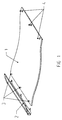
- Fig. 1 is a ceiling panel 1 for the design of the aircraft interior in shown in perspective view.
- the illustrated ceiling panel 1 serves as cover the ceiling area of the aircraft interior above the passage between the rows of seats.
- a side panel 2 which, for example can be designed so that it serves as a cover for the lamps to illuminate the Airplane interior serves.
- On the side panel 2 usually closes the bottom Luggage compartment (not shown).
- On the right side of the ceiling panel 1 can also connect a side panel in the form of a lamp cover (not shown).
- the invention are on one edge side of the ceiling panel 1 fasteners arranged, which a loose storage of the ceiling panel 1 at one, usually on Allow aircraft fuselage mounted support structure.
- the Fasteners the shape of bolts 3, which in accordance complementary designed elements are attached to the support structure, so over the bolt 3 in the essentially only forces are absorbed in vertical action, so that the Ceiling panel 1 is suspended via the bolt 3 quasi on the fuselage.
- the fasteners of this fixed bearing have the shape of bolt 4, which are fastened on correspondingly complementarily designed elements in the manner so that the bolts 4 also absorb forces in the direction of the ceiling panel 1.
- devices are provided on the fixed bearing side, which a allow tool-free opening of fasteners of bolts 4.
- the bolts 3 of the floating bearing advantageously from the Longitudinal center of the passenger compartment are turned away, so that the maintenance of the behind the Ceiling panel 1 located facilities easier is possible.
- the bolts 3, 4 are firmly connected to the ceiling panel 1, for example glued or screwed.
- the From the interior of the aircraft visible side of the ceiling panel 1 has no Openings od.
- panel is to be understood in its broadest meaning and can be used as any Cover be formed whose purpose is to devices, devices od. Like. In one Basic or supporting structure to dress and possibly flush with a Covering wall od. Like. Complete.
- FIGS. 2a to 2c A preferred embodiment of a fixed bearing is shown in FIGS. 2a to 2c.
- Fig. 2a is fixed in the ceiling panel 1 at the edge a bolt 4, e.g. glued.
- Bolt 4 is a damping ring 5 made of elastic material, for example made of rubber arranged, which dampens the vibrations and noises.
- the fuselage is one Support structure, for example, a rail 6 with C-shaped cross section in Connected longitudinally of the aircraft. At the rail 6 are at the corresponding bodies, the means for fastening the bolt 4 in a known manner attached.
- a bearing block 7 by means of a screw 8, e.g. a countersunk screw and a threaded bar 9 at the Profile rail 6 attached.
- the thread of the bolt 9 is preferably carried out self-locking.
- the bearing blocks 7 are fixed along the rail 6 arranged.
- the other end of the bearing block 7 has a bore in which a socket 10th is arranged, via which a rotary lever 11 and a bracket 12 with the bearing block get connected.
- the bush 10 can od by means not shown.
- the bearing block 7 be secured against twisting.
- the bolt 4 is through the hole in the socket 10th plugged, wherein a locking of the bolt 4 with the bearing block 7 by a barb-shaped design of the free end of the bolt 4 and a corresponding shape the clip 12 is enabled.
- Fig. 2a shows yet another to the ceiling panel 1 subsequent side panel 2, which by a corresponding Form is held by the ceiling panel 1.
- a fixed to the bearing block 7 spring 13 the side panel 2 to the Top of the ceiling panel 1.
- To access the rotary lever 11 for disassembly of the Ceiling panels 1 to allow the side panel 2 is pushed to the outside, so that a Gap between the ceiling panel 1 and the side panel 2 is released by which the access to the rotary lever 11 is made possible.
- the rotary levers 11 with a conspicuous color, e.g. highlighted in red.
- the rotary lever 11 is in the locked position.
- the shutter be unlocked.
- the free end of the bolt 4 is formed so that at Rotation of the rotary lever 11 and the associated bracket 12 this automatically is widened, so that the bolt 4 are pulled out of the socket 10 in the bearing block 7 can.
- this would automatically when twisting the Rotary lever 11 of each closure to the unlocking position due to gravity after fold down. This facilitates disassembly.
- tethers 15 can have one end attached to the bearing block 7 of the fixed bearing and with its other end to the ceiling panel 1 become.
- the ceiling panel 1 is open at fixed bearings in one of the length of the or held each tether 15 corresponding position. Nevertheless, a complete Disassembly of the ceiling panel 1, the or each tether 15 without Use of tools quickly and easily solvable. This may be, for example, as shown by Loops at the ends of the tether 15, which via corresponding formations on Bearing 7 or slipped on the ceiling panel 1 can be achieved.
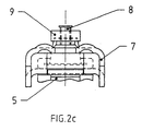
- Fig. 2c shows the sake of completeness nor a side view of the fixed bearing of FIG. 2a from the left, wherein the rail 6 is not shown.
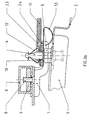
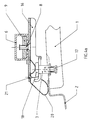
- FIGS. 3a and 3b another embodiment of a fixed bearing is shown.
- These Variant in contrast to the embodiment according to FIGS. 2a to 2c none Return spring on.
- this variant has holding means for protecting the rotary lever 11 against accidental operation.
- the rotary lever 11 is in unlocked position.
- the lock is locked.
- the shutter is unlocked again. Due to the fact that the rotary lever 11 can be unlocked from the locked position in both directions is the Disassembly of the ceiling panel 1 facilitates because the direction of rotation of the rotary lever 11 is not must be taken into account.
- a ball fixation which consists of a hole 23 in the rotary lever 11 and a ball 24, whose diameter is larger than that of the hole 23, consists.
- the embodiment of the movable bearing according to FIGS. 4a to 4c again consists of a Bearing 16, in the same manner as the bearing block 7 at the fixed bearing with the help of a Screw 8, in this case e.g. a lens screw, and a latch 9 on the profile strip. 6 is fixed at locations corresponding to the arrangement of the bolt 3 on the ceiling panel 1.
- a Screw 8 in this case e.g. a lens screw
- a latch 9 on the profile strip. 6 is fixed at locations corresponding to the arrangement of the bolt 3 on the ceiling panel 1.
- the Bolt 3 of the floating bearing is in an insert 17, which is firmly connected to the ceiling panel 1, for example, glued, screwed.
- the bolt 3 is at his, the ceiling panel. 1 facing away from the free end with a head 18 which is greater than the diameter of the Bolzens 3. This allows the bolt 3 in a corresponding slot 19 in the bearing block 16th are inserted (see Fig. 4c).
- the spring 20 has two functions. On the one hand, the head 18 of the Bolzens 3 pressed against the bearing block, and on the other hand is at best to the Ceiling panel 1 subsequent side panel 2 pressed to the top of the ceiling panel, to avoid vibrations in both cases. As can be seen from FIG. 4b, the slot 19 is in the bearing block 16 by mutual rounding 22 expands outward to an insertion to facilitate the bolt 3 in the slot. From the view of FIG. 4c of the slot 19 in Bearing 16 recognizable, in which the bolt 3 is inserted, which due to the Head 18 is held in the bearing block 16.
Landscapes
- Engineering & Computer Science (AREA)
- Aviation & Aerospace Engineering (AREA)
- Mechanical Engineering (AREA)
- Connection Of Plates (AREA)
- Combined Means For Separation Of Solids (AREA)
- Storage Of Web-Like Or Filamentary Materials (AREA)
- Battery Mounting, Suspending (AREA)
- Helmets And Other Head Coverings (AREA)
- Casings For Electric Apparatus (AREA)
Description
- Fig. 1
- eine perspektivische Ansicht eines mit der erfindungsgemäßen Einrichtung versehenen Deckenpaneels sowie einer daran anschließenden Lampenabdeckung,
- Fig. 2a
- eine Ausführungsform eines Festlagers in lotrechtem Querschnitt,
- Fig. 2b
- das Festlager gemäß Fig. 2a in der Ansicht von oben,
- Fig. 2c
- eine Seitenansicht der Anordnung gemäß Fig. 2a von links,
- Fig. 3a
- eine andere Ausführungsform eines Festlagers in lotrechtem Querschnitt,
- Fig. 3b
- das Festlager gemäß Fig. 3a in der Ansicht von oben,
- Fig. 4a
- eine Ausführungsform eines Loslagers in lotrechtem Querschnitt,
- Fig. 4b
- das Loslager gemäß Fig. 4a in der Ansicht von oben, und
- Fig. 4c
- eine Seitenansicht der Anordnung gemäß Fig. 4a von rechts.
Claims (27)
- Anordnung umfassend eine Abdeckplatte (1), eine Tragkonstruktion (6), und eine Einrichtung mit mindestens zwei Befestigungselementen (3, 4), wobei alle Bestandteile der Befestigungselemente (3, 4) zur Verbindung mit der Abdeckplatte (1) und der Tragkonstruktion (6) eingerichtet sind, wobei die zur Verbindung mit der Abdeckplatte (1) eingerichteten Befestigungselemente (3, 4) ausschließlich mit der, der Tragkonstruktion (6) zugewandten Seite der Abdeckplatte (1) verbindbar sind, dadurch gekennzeichnet, dass zumindest ein Befestigungselement (3) als Loslager zur Aufnahme der im Wesentlichen senkrecht zur Abdeckplatte (1) wirkenden Kräfte und zumindest ein Befestigungselement (4) als Festlager zur Aufnahme auch der im Wesentlichen in Richtung der Abdeckplatte (1) wirkenden Kräfte ausgebildet ist, und dass das oder jedes als Festlager ausgebildete Befestigungselement (4) Mittel zur werkzeuglosen Verund Entriegelung aufweist.
- Anordnung nach Anspruch 1, dadurch gekennzeichnet, dass alle Befestigungselemente zur randseitigen Verbindung mit der Abdeckplatte (1) eingerichtet sind.
- Anordnung nach Anspruch 2, dadurch gekennzeichnet, dass jedes als Loslager ausgebildete Befestigungselement zur Verbindung an einer Randseite der Abdeckplatte (1) und dass jedes als Festlager ausgebildete Befestigungselement zur Verbindung an der gegenüberliegenden Randseite der Abdeckplatte (1) eingerichtet ist.
- Anordnung nach mindestens einem der Ansprüche 1 bis 3, dadurch gekennzeichnet, dass jedes als Loslager ausgebildete Befestigungselement durch einen mit der Abdeckplatte (1) fest verbindbaren Bolzen (3) gebildet ist, welcher Bolzen (3) in einen mit der Tragkonstruktion (6) fest verbindbaren Lagerbock (16) einhängbar ist, und dass jedes als Festlager ausgebildete Befestigungselement als Schnappverschluss (4, 12) ausgebildet ist, welcher Schnappverschluss (4, 12) werkzeuglos öffenbar ist.
- Anordnung nach Anspruch 4, dadurch gekennzeichnet, dass der Bolzen (3) mit der Abdeckplatte (1) durch Verklebung verbindbar ist, und dass der Bolzen (3) mit einem Kopf (18) ausgebildet ist.
- Anordnung nach Anspruch 4 oder 5, dadurch gekennzeichnet, dass der Lagerbock (16) kastenförmige, einseitig offene, unten geschlitzte Gestalt besitzt.
- Anordnung nach einem der Ansprüche 4 bis 6, dadurch gekennzeichnet, dass am Lagerbock (16) eine Feder (20) befestigt ist, die derart geformt ist, dass sie den Bolzen (3) mit dem Kopf (18) festhält.
- Anordnung nach einem der Ansprüche 4 bis 7, dadurch gekennzeichnet, dass jedes als Schnappverschluss (4, 12) ausgebildete Festlager durch einen seitlich der Abdeckplatte (1) zugänglichen Drehhebel (11) werkzeuglos öffenbar ist.
- Anordnung nach Anspruch 8, gekennzeichnet durch eine auf den Drehhebel (11) wirkende Rückstellfeder (14), durch welche der Drehhebel (11) im offenem Zustand des Schnappverschlusses (4, 12) in eine entriegelnde Stellung bringbar ist.
- Anordnung nach Anspruch 8, dadurch gekennzeichnet, dass der Drehhebel (11) zum Schutz vor ungewollter Betätigung in der, den Schnappverschluss (4, 12) verriegelnden Stellung Haltemittel (13, 23, 24) aufweist, wobei der Drehhebel (11) in Überwindung dieser Haltemittel (13, 23, 24) in eine, den Schnappverschluss (4, 12) entriegelnde Stellung bringbar ist.
- Anordnung nach einem der Ansprüche 4 bis 10, dadurch gekennzeichnet, dass jedes als Schnappverschluss ausgebildete Festlager durch einen mit der Abdeckplatte (1) vorzugsweise durch Verklebung fest verbindbaren Bolzen (4) gebildet ist, welcher Bolzen (4) am freien Ende zugespitzt und mit seitlichen Kerben versehen ist, und dass eine mit der Tragkonstruktion (6) verbindbare Klammer (12) vorgesehen ist, deren zwei federnde Enden in die Kerben des Bolzens (4) eingreifen, wobei die Klammer (12) um die Achse des Bolzens (4) gegenüber der Tragkonstruktion (6) drehbar angeordnet ist.
- Anordnung nach Anspruch 11, dadurch gekennzeichnet, dass die Klammer (12) durch eine dreieckförmig gebogene Blattfeder mit einer Bohrung im mittleren Basisteil für den Durchtritt des Bolzens (4) gebildet ist, und dass die Klammer (12) mit einem Drehhebel (11) verbunden und mit diesem in einem Lagerbock (7) oder einem damit verbundenen Bauteil um ihre Symmetrieachse drehbar gelagert ist.
- Anordnung nach Anspruch 11 oder 12, dadurch gekennzeichnet, dass die Klammer (12) und der Drehhebel (11) über eine Buchse (10) miteinander verbunden und die Buchse (10) in einer Bohrung des Lagerbocks (7) oder einem damit verbundenen Bauteil drehbar gelagert ist.
- Anordnung nach einem der Ansprüche 11 bis 13, dadurch gekennzeichnet, dass zwischen dem Drehhebel (11) und dem Lagerbock (7) oder einem damit verbundenen Bauteil eine Rückstellfeder (14) vorgesehen ist, die die Klammer (12) in die Offenstellung zwingt und dass Klammer (12) und Kerben im Bolzen (4) derart ausgebildet sind, dass die Klammer (12) im eingerasteten Zustand durch die Kerben im Bolzen (4) in Schließstellung gehalten wird.
- Anordnung nach einem der Ansprüche 11 bis 14, dadurch gekennzeichnet, dass der die Klammer (12) tragende Lagerbock (7) oder ein damit verbundener Bauteil mit der Tragkonstruktion (6) über eine Schraube (8) und einen Riegel (9) verbunden ist.
- Anordnung nach einem der Ansprüche 1 bis 15, dadurch gekennzeichnet, dass zumindest ein Halteseil (15) jeweils mit dem einen Ende an der Abdeckplatte (1) bzw. einem damit verbundenen Bauteil und jeweils mit dem anderen Ende an der Tragkonstruktion (6) bzw. einem damit verbundenen Bauteil befestigbar ist, und dass die Befestigungen des oder jedes Halteseils (15) werkzeuglos öffenbar sind.
- Anordnung nach einem der Ansprüche 1 bis 16, dadurch gekennzeichnet, dass die Befestigungselemente Mittel zur Dämpfung von Vibrationen, beispielsweise Dämpfungsringe (5) aus elastischem Material oder Federn (13, 20) aufweisen.
- Anordnung nach einem der Ansprüche 1 bis 17, dadurch gekennzeichnet, dass an den Befestigungselementen Einrichtungen zur lösbaren Verbindung der Abdeckplatte (1) mit daran anschließenden Abdeckplatten (2) vorgesehen sind.
- Anordnung nach Anspruch 18, dadurch gekennzeichnet, dass die Einrichtungen zur lösbaren Verbindung der Abdeckplatte (1) mit daran anschließenden Abdeckplatten (2) durch Federelemente (13, 20) gebildet sind.
- Abdeckplatte (1) für eine Anordnung gemäß einem der Ansprüche 1 bis 19, mit zumindest zwei Befestigungselementen (3, 4) zur Verbindung der Abdeckplatte (1) mit einer Tragkonstruktion (6), wobei die Befestigungselemente (3, 4) ausschließlich an der, der Tragkonstruktion (6) zugewandten Seite der Abdeckplatte (1) angeordnet sind, dadurch gekennzeichnet, dass zumindest ein Befestigungselement (3) als Loslager zur Aufnahme der im Wesentlichen senkrecht zur Abdeckplatte (1) wirkenden Kräfte und zumindest ein Befestigungselement (4) als Festlager zur Aufnahme auch der im Wesentlichen in Richtung der Abdeckplatte (1) wirkenden Kräfte ausgebildet ist, und dass das oder jedes als Festlager ausgebildete Befestigungselement (4) Mittel zur werkzeuglosen Ver- und Entriegelung aufweist.
- Abdeckplatte nach Anspruch 20, dadurch gekennzeichnet, dass alle Befestigungselemente (3, 4) randseitig der Abdeckplatte (1) angeordnet sind.
- Abdeckplatte nach Anspruch 21, dadurch gekennzeichnet, dass jedes als Loslager ausgebildete Befestigungselement (3) an einer Randseite der Abdeckplatte (1) und dass jedes als Festlager ausgebildete Befestigungselement (4) an der gegenüberliegenden Randseite der Abdeckplatte (1) angeordnet ist.
- Abdeckplatte nach mindestens einem der Ansprüche 20 bis 22, dadurch gekennzeichnet, dass jedes als Loslager ausgebildete Befestigungselement (3) durch einen mit der Abdeckplatte (1) fest verbundenen Bolzen (3) gebildet ist, welcher Bolzen (3) in einen mit der Tragkonstruktion (6) fest verbindbaren Lagerbock (16) einhängbar ist, und dass jedes als Festlager ausgebildete Befestigungselement (4) als Schnappverschluss (4, 12) ausgebildet ist, welcher Schnappverschluss (4, 12) werkzeuglos öffenbar ist.
- Abdeckplatte nach Anspruch 23, dadurch gekennzeichnet, dass der Bolzen (3) mit der Abdeckplatte (1) verklebt ist, und dass der Bolzen (3) mit einem Kopf (18) ausgebildet ist.
- Abdeckplatte nach Anspruch 23 oder 24, dadurch gekennzeichnet, dass jedes als Schnappverschluss ausgebildete Festlager durch einen mit der Abdeckplatte (1) verklebten Bolzen (4) gebildet ist, welcher Bolzen (4) am freien Ende zugespitzt und mit seitlichen Kerben versehen ist, und dass eine mit der Tragkonstruktion (6) verbindbare Klammer (12) vorgesehen ist, deren zwei federnde Enden in die Kerben des Bolzens (4) eingreifen, wobei die Klammer (12) um die Achse des Bolzens (4) gegenüber der Tragkonstruktion (6) drehbar angeordnet ist.
- Abdeckplatte nach einem der Ansprüche 20 bis 25, dadurch gekennzeichnet, dass zumindest ein Halteseil (15) jeweils mit dem einen Ende an der Abdeckplatte (1) bzw. einem damit verbundenen Bauteil verbunden ist und jeweils mit dem anderen Ende an der Tragkonstruktion (6) bzw. einem damit verbundenen Bauteil befestigbar ist, und dass die Befestigungen des oder jedes Halteseils (15) werkzeuglos öffenbar sind.
- Abdeckplatte nach einem der Ansprüche 20 bis 26, dadurch gekennzeichnet, dass die Befestigungselemente Mittel zur Dämpfung von Vibrationen, beispielsweise Dämpfungsringe (5) aus elastischem Material oder Federn (13, 20) aufweisen.
Priority Applications (1)
| Application Number | Priority Date | Filing Date | Title |
|---|---|---|---|
| AT98890196T ATE289940T1 (de) | 1997-07-07 | 1998-07-07 | Einrichtung zur lösbaren befestigung von abdeckplatten od-dgl. |
Applications Claiming Priority (3)
| Application Number | Priority Date | Filing Date | Title |
|---|---|---|---|
| AT0116297A AT404926B (de) | 1997-07-07 | 1997-07-07 | Einrichtung zur lösbaren befestigung von abdeckplatten od. dgl. |
| AT116297 | 1997-07-07 | ||
| AT1162/97 | 1997-07-07 |
Publications (3)
| Publication Number | Publication Date |
|---|---|
| EP0894710A2 EP0894710A2 (de) | 1999-02-03 |
| EP0894710A3 EP0894710A3 (de) | 2001-02-21 |
| EP0894710B1 true EP0894710B1 (de) | 2005-03-02 |
Family
ID=3507952
Family Applications (1)
| Application Number | Title | Priority Date | Filing Date |
|---|---|---|---|
| EP98890196A Expired - Lifetime EP0894710B1 (de) | 1997-07-07 | 1998-07-07 | Einrichtung zur lösbaren Befestigung von Abdeckplatten od-dgl. |
Country Status (6)
| Country | Link |
|---|---|
| US (1) | US6199798B1 (de) |
| EP (1) | EP0894710B1 (de) |
| AT (2) | AT404926B (de) |
| CA (1) | CA2242129A1 (de) |
| DE (1) | DE59812605D1 (de) |
| ES (1) | ES2236886T3 (de) |
Families Citing this family (26)
| Publication number | Priority date | Publication date | Assignee | Title |
|---|---|---|---|---|
| DE10017410B4 (de) * | 2000-04-07 | 2005-06-23 | Airbus Deutschland Gmbh | Vorrichtung zum Halten von Ausstattungskomponenten in einer Passagierkabine |
| US6874730B2 (en) * | 2001-09-03 | 2005-04-05 | Goodrich Hella Aerospace Lighting Systems Gmbh | Covering element for the interior of a vehicle, particularly an aircraft |
| AT410657B (de) * | 2001-10-09 | 2003-06-25 | Fischer Adv Components Gmbh | Überkopf-gepäckablagebehälter, insbesondere für flugzeuge |
| US6814331B2 (en) * | 2002-05-10 | 2004-11-09 | Goodrich Hella Aerospace Lighting Systems Gmbh | Device for removably fastening a first part to a second part mountable in an aircraft |
| US6712316B2 (en) * | 2002-08-01 | 2004-03-30 | The Boeing Company | Snap-on sidewall assembly |
| US6721993B1 (en) * | 2002-10-23 | 2004-04-20 | Carrier Corporation | Hinge assembly for air handling system |
| US6951321B2 (en) * | 2003-03-27 | 2005-10-04 | The Boeing Company | Efficient cargo liner installation |
| US20060032155A1 (en) * | 2004-07-23 | 2006-02-16 | Goodrich Hella Aerospace Lighting Systems Gmbh | Device for holding a partition wall on a wall in the interior of a vehicle |
| US7562846B2 (en) * | 2005-11-10 | 2009-07-21 | The Boeing Company | Window retaining system |
| DE102006042337B3 (de) * | 2006-09-08 | 2008-04-03 | Airbus Deutschland Gmbh | Halteelement zur Befestigung eines Ausstattungselements an einer Tragschiene |
| AT505901B1 (de) * | 2008-04-02 | 2009-05-15 | Facc Ag | Deckenpaneel für die verkleidung des innenraums von fahrzeugen |
| FR2946008B1 (fr) * | 2009-05-28 | 2012-12-28 | Airbus France | Aeronef comprenant des traverses de support de plancher |
| DE102009038644B4 (de) * | 2009-08-24 | 2015-01-08 | Airbus Operations Gmbh | Dekompressionselementbefestigungssystem für ein Flugzeug |
| DE102010017822A1 (de) * | 2010-04-20 | 2011-10-20 | Airbus Operations Gmbh | Flugzeuginnenausstattungsbauteil und Flugzeuginnenausstattungsbauteilsystem |
| AT510670B1 (de) * | 2010-10-19 | 2012-09-15 | Weingaertner Werner | Einbauvorrichtung für einbauelemente |
| EP2923950B1 (de) * | 2014-03-27 | 2019-02-20 | Airbus Operations GmbH | Modul zum Abdichten einer Schnittstelle in einem Flugzeug |
| US9567774B1 (en) | 2015-05-15 | 2017-02-14 | Northrop Grumman Systems Corporation | Temporally staged rapid panel access fastener for highly curved panels |
| US9458648B1 (en) | 2015-05-15 | 2016-10-04 | Northrop Grumman Systems Corporation | Rapid panel access fastener for highly curved panels |
| US9845143B2 (en) | 2015-07-20 | 2017-12-19 | Northrop Grumman Systems Corporation | Advanced lock design for ball-lock devices |
| US10179638B2 (en) | 2015-08-31 | 2019-01-15 | The Boeing Company | Crown raceway support (CRS) for crown integration panel (CIP) |
| US10011343B2 (en) | 2015-08-31 | 2018-07-03 | The Boeing Company | Self-aligning structural attachment for crown integration panel (CIP) |
| US10259559B2 (en) | 2015-08-31 | 2019-04-16 | The Boeing Company | Remotely-activated self-centering cable latch |
| US10053204B2 (en) | 2015-08-31 | 2018-08-21 | The Boeing Company | Adjustable support structure for aircraft cabin ceiling |
| US9758233B2 (en) | 2015-08-31 | 2017-09-12 | The Boeing Company | Support system having a crown integration panel (CIP) |
| CN108045546A (zh) * | 2017-09-20 | 2018-05-18 | 中国水利水电科学研究院 | 一种轻小型固定翼无人机载荷快速连接与更换装置 |
| CN116498108A (zh) * | 2023-04-20 | 2023-07-28 | 东南大学 | 一种提高空间钢结构抗倒塌性能的索撑节点 |
Family Cites Families (13)
| Publication number | Priority date | Publication date | Assignee | Title |
|---|---|---|---|---|
| DE1938428B2 (de) * | 1969-07-29 | 1971-07-01 | Vxxxxxxx verbindungsanordnung zur loesbaren verbindung zweier bauteile | |
| US3685235A (en) * | 1970-09-21 | 1972-08-22 | Bajer Ind Inc | Suspended ceiling system including a grid network |
| US3765465A (en) | 1972-01-05 | 1973-10-16 | Deutsch Fastener Corp | Retractable captive fastener |
| US4050208A (en) * | 1976-10-04 | 1977-09-27 | The Boeing Company | Aircraft interior ceiling panel assembly and attachment apparatus |
| DE3626514A1 (de) | 1986-08-05 | 1988-02-11 | Camloc Gmbh | Verschluss zum verbinden plattenfoermiger bauteile |
| US4739955A (en) * | 1986-09-30 | 1988-04-26 | The Boeing Company | Aircraft cabin panel and insulation retainer with integrated use as a spacer-isolator |
| DE3814183C1 (en) * | 1988-04-27 | 1989-09-14 | Messerschmitt-Boelkow-Blohm Gmbh, 8012 Ottobrunn, De | Fastening device for components in the form of panels |
| DE3900468A1 (de) | 1989-01-10 | 1990-07-12 | Camloc Gmbh | Vorrichtung zum loesbaren befestigen zweier bauteile |
| US5014934A (en) | 1989-06-30 | 1991-05-14 | The Boeing Company | Removable seal for discontinuities in aircraft skin |
| DE4032565C2 (de) | 1990-10-13 | 1994-08-18 | Camloc Gmbh | Vorrichtung zum lösbaren Verbinden zweier Bauteile |
| DE9016393U1 (de) * | 1990-12-03 | 1991-02-21 | Schwarz Verbindungs-Systeme, 71263 Weil der Stadt | Vorrichtung zum Verbinden mehrerer Teile |
| US5822935A (en) * | 1996-12-19 | 1998-10-20 | Steelcase Inc. | Solid-core wall system |
| DE29716096U1 (de) * | 1997-09-08 | 1997-10-30 | Schwarz Verbindungs-Systeme GmbH, 75382 Althengstett | Schnellverschluß |
-
1997
- 1997-07-07 AT AT0116297A patent/AT404926B/de not_active IP Right Cessation
-
1998
- 1998-06-30 CA CA002242129A patent/CA2242129A1/en not_active Abandoned
- 1998-07-07 ES ES98890196T patent/ES2236886T3/es not_active Expired - Lifetime
- 1998-07-07 AT AT98890196T patent/ATE289940T1/de active
- 1998-07-07 EP EP98890196A patent/EP0894710B1/de not_active Expired - Lifetime
- 1998-07-07 US US09/111,060 patent/US6199798B1/en not_active Expired - Lifetime
- 1998-07-07 DE DE59812605T patent/DE59812605D1/de not_active Expired - Lifetime
Also Published As
| Publication number | Publication date |
|---|---|
| ATA116297A (de) | 1998-08-15 |
| AT404926B (de) | 1999-03-25 |
| ATE289940T1 (de) | 2005-03-15 |
| CA2242129A1 (en) | 1999-01-07 |
| DE59812605D1 (de) | 2005-04-07 |
| US6199798B1 (en) | 2001-03-13 |
| ES2236886T3 (es) | 2005-07-16 |
| EP0894710A2 (de) | 1999-02-03 |
| EP0894710A3 (de) | 2001-02-21 |
Similar Documents
| Publication | Publication Date | Title |
|---|---|---|
| AT404926B (de) | Einrichtung zur lösbaren befestigung von abdeckplatten od. dgl. | |
| DE102006042337B3 (de) | Halteelement zur Befestigung eines Ausstattungselements an einer Tragschiene | |
| DE69818603T2 (de) | System zum befestigen von zubehörteilen an selbsttragenden paneelen und/oder elementen der innenverkleidung von fahrzeugen | |
| EP2358593B1 (de) | Vorrichtung zum befestigen eines objekts an einer schiene | |
| EP2252508B1 (de) | Vorrichtung zur lösbaren bodenbefestigung von schränken oder dergleichen in bordküchen von flugzeugen | |
| DE19833708A1 (de) | Höhenverstellbares Hängesystem mit Diebstahlsicherung | |
| EP1062123B1 (de) | Vorrichtung zum befestigen eines ersten teils an einem feststehenden zweiten teil | |
| EP2021244A1 (de) | Vorrichtung zum festlegen eines gegenstandes | |
| EP0893341A2 (de) | Fenstereinheit für Flugzeugkabinen | |
| DE60106194T2 (de) | Installationsgerät | |
| DE2735660C3 (de) | Befestigungsvorrichtung, insbesondere für eine Bordschalttafel eines Automobils | |
| EP0407767B1 (de) | Trageinrichtung für einen Vorhang | |
| EP2572415A2 (de) | Türanordnung für einen geräteschrank und verfahren zum ändern einer anschlagsseite einer türanordnung | |
| DE102012208482A1 (de) | Befestigungsvorrichtung | |
| DE202006004081U1 (de) | Anordnung zur lösbaren Befestigung von Bauteilen an einer Decke oder Wand | |
| DE102004009346A1 (de) | Klappenanordnung für O2 Maskencontainer | |
| EP1328321A1 (de) | Rettungsgerät mit verstellbarer armlänge | |
| DE102018120609A1 (de) | Trennvorrichtung und Verfahren zur Installation einer Trennvorrichtung in einer Passagierkabine | |
| EP1607329A1 (de) | Schnellwechselbeschlag | |
| DE102020109188A1 (de) | Befestigungssystem, Monument und Verfahren zum Anbringen eines Ausstattungsgegenstands an einem Monument | |
| DE202014103236U1 (de) | Befestigen von Verkleidungsteilen an einer Unterkonstruktion | |
| DE4115815C1 (en) | Quick-action component fastener with bolt(s) - which is fitted to body slidable longitudinally w.r.t. fastener | |
| WO2017167600A1 (de) | Geschwindigkeitsbegrenzer mit einer schutzhaube | |
| DE20118244U1 (de) | Vorrichtung zum Befestigen von Schutzverkleidungen | |
| DE102018120621A1 (de) | Faltbare Trennvorrichtung und Verfahren zur Installation einer faltbaren Trennvorrichtung in einer Passagierkabine |
Legal Events
| Date | Code | Title | Description |
|---|---|---|---|
| PUAI | Public reference made under article 153(3) epc to a published international application that has entered the european phase |
Free format text: ORIGINAL CODE: 0009012 |
|
| AK | Designated contracting states |
Kind code of ref document: A2 Designated state(s): AT DE ES FR GB IT |
|
| AX | Request for extension of the european patent |
Free format text: AL;LT;LV;MK;RO;SI |
|
| PUAL | Search report despatched |
Free format text: ORIGINAL CODE: 0009013 |
|
| AK | Designated contracting states |
Kind code of ref document: A3 Designated state(s): AT BE CH CY DE DK ES FI FR GB GR IE IT LI LU MC NL PT SE |
|
| AX | Request for extension of the european patent |
Free format text: AL;LT;LV;MK;RO;SI |
|
| 17P | Request for examination filed |
Effective date: 20010730 |
|
| AKX | Designation fees paid |
Free format text: AT DE ES FR GB IT |
|
| RAP1 | Party data changed (applicant data changed or rights of an application transferred) |
Owner name: FISCHER ADVANCED COMPOSITE COMPONENTS AG |
|
| 17Q | First examination report despatched |
Effective date: 20020806 |
|
| GRAP | Despatch of communication of intention to grant a patent |
Free format text: ORIGINAL CODE: EPIDOSNIGR1 |
|
| GRAS | Grant fee paid |
Free format text: ORIGINAL CODE: EPIDOSNIGR3 |
|
| GRAA | (expected) grant |
Free format text: ORIGINAL CODE: 0009210 |
|
| RIN1 | Information on inventor provided before grant (corrected) |
Inventor name: FILSEGGER, HERMANN, DIPL.-ING. Inventor name: STEPHAN, WALTER, DIPL.-ING. |
|
| AK | Designated contracting states |
Kind code of ref document: B1 Designated state(s): AT DE ES FR GB IT |
|
| REG | Reference to a national code |
Ref country code: GB Ref legal event code: FG4D Free format text: NOT ENGLISH |
|
| REF | Corresponds to: |
Ref document number: 59812605 Country of ref document: DE Date of ref document: 20050407 Kind code of ref document: P |
|
| GBT | Gb: translation of ep patent filed (gb section 77(6)(a)/1977) |
Effective date: 20050603 |
|
| REG | Reference to a national code |
Ref country code: ES Ref legal event code: FG2A Ref document number: 2236886 Country of ref document: ES Kind code of ref document: T3 |
|
| PLBE | No opposition filed within time limit |
Free format text: ORIGINAL CODE: 0009261 |
|
| STAA | Information on the status of an ep patent application or granted ep patent |
Free format text: STATUS: NO OPPOSITION FILED WITHIN TIME LIMIT |
|
| 26N | No opposition filed |
Effective date: 20051205 |
|
| ET | Fr: translation filed | ||
| REG | Reference to a national code |
Ref country code: FR Ref legal event code: CD |
|
| REG | Reference to a national code |
Ref country code: FR Ref legal event code: PLFP Year of fee payment: 19 |
|
| REG | Reference to a national code |
Ref country code: FR Ref legal event code: PLFP Year of fee payment: 20 |
|
| PGFP | Annual fee paid to national office [announced via postgrant information from national office to epo] |
Ref country code: ES Payment date: 20170809 Year of fee payment: 20 Ref country code: FR Payment date: 20170720 Year of fee payment: 20 Ref country code: IT Payment date: 20170718 Year of fee payment: 20 Ref country code: DE Payment date: 20170728 Year of fee payment: 20 Ref country code: GB Payment date: 20170712 Year of fee payment: 20 |
|
| PGFP | Annual fee paid to national office [announced via postgrant information from national office to epo] |
Ref country code: AT Payment date: 20170726 Year of fee payment: 20 |
|
| REG | Reference to a national code |
Ref country code: DE Ref legal event code: R071 Ref document number: 59812605 Country of ref document: DE |
|
| REG | Reference to a national code |
Ref country code: GB Ref legal event code: PE20 Expiry date: 20180706 |
|
| REG | Reference to a national code |
Ref country code: AT Ref legal event code: MK07 Ref document number: 289940 Country of ref document: AT Kind code of ref document: T Effective date: 20180707 |
|
| PG25 | Lapsed in a contracting state [announced via postgrant information from national office to epo] |
Ref country code: GB Free format text: LAPSE BECAUSE OF EXPIRATION OF PROTECTION Effective date: 20180706 |
|
| REG | Reference to a national code |
Ref country code: ES Ref legal event code: FD2A Effective date: 20220128 |
|
| PG25 | Lapsed in a contracting state [announced via postgrant information from national office to epo] |
Ref country code: ES Free format text: LAPSE BECAUSE OF EXPIRATION OF PROTECTION Effective date: 20180708 |