EP0894711A2 - Trennbare Kupplung für eine Heckrotor-Kraftübertragungsvorrichtung eines Hubschraubers - Google Patents
Trennbare Kupplung für eine Heckrotor-Kraftübertragungsvorrichtung eines Hubschraubers Download PDFInfo
- Publication number
- EP0894711A2 EP0894711A2 EP98114559A EP98114559A EP0894711A2 EP 0894711 A2 EP0894711 A2 EP 0894711A2 EP 98114559 A EP98114559 A EP 98114559A EP 98114559 A EP98114559 A EP 98114559A EP 0894711 A2 EP0894711 A2 EP 0894711A2
- Authority
- EP
- European Patent Office
- Prior art keywords
- coupling
- transmission
- shaft
- transmission members
- lead
- Prior art date
- Legal status (The legal status is an assumption and is not a legal conclusion. Google has not performed a legal analysis and makes no representation as to the accuracy of the status listed.)
- Granted
Links
- 230000008878 coupling Effects 0.000 title claims abstract description 75
- 238000010168 coupling process Methods 0.000 title claims abstract description 75
- 238000005859 coupling reaction Methods 0.000 title claims abstract description 75
- 230000005540 biological transmission Effects 0.000 title claims abstract description 65
- 230000000712 assembly Effects 0.000 claims abstract description 11
- 238000000429 assembly Methods 0.000 claims abstract description 11
- 239000000463 material Substances 0.000 claims description 2
- 230000002093 peripheral effect Effects 0.000 description 3
- 239000000203 mixture Substances 0.000 description 2
- 230000013011 mating Effects 0.000 description 1
- 238000005096 rolling process Methods 0.000 description 1
Images


Classifications
-
- B—PERFORMING OPERATIONS; TRANSPORTING
- B64—AIRCRAFT; AVIATION; COSMONAUTICS
- B64C—AEROPLANES; HELICOPTERS
- B64C27/00—Rotorcraft; Rotors peculiar thereto
- B64C27/32—Rotors
- B64C27/46—Blades
- B64C27/473—Constructional features
- B64C27/50—Blades foldable to facilitate stowage of aircraft
-
- B—PERFORMING OPERATIONS; TRANSPORTING
- B64—AIRCRAFT; AVIATION; COSMONAUTICS
- B64C—AEROPLANES; HELICOPTERS
- B64C1/00—Fuselages; Constructional features common to fuselages, wings, stabilising surfaces or the like
- B64C1/06—Frames; Stringers; Longerons ; Fuselage sections
- B64C1/061—Frames
- B64C1/063—Folding or collapsing to reduce overall dimensions, e.g. foldable tail booms
-
- B—PERFORMING OPERATIONS; TRANSPORTING
- B64—AIRCRAFT; AVIATION; COSMONAUTICS
- B64C—AEROPLANES; HELICOPTERS
- B64C1/00—Fuselages; Constructional features common to fuselages, wings, stabilising surfaces or the like
- B64C1/30—Parts of fuselage relatively movable to reduce overall dimensions of aircraft
-
- B—PERFORMING OPERATIONS; TRANSPORTING
- B64—AIRCRAFT; AVIATION; COSMONAUTICS
- B64C—AEROPLANES; HELICOPTERS
- B64C27/00—Rotorcraft; Rotors peculiar thereto
- B64C27/04—Helicopters
- B64C27/12—Rotor drives
-
- B—PERFORMING OPERATIONS; TRANSPORTING
- B64—AIRCRAFT; AVIATION; COSMONAUTICS
- B64C—AEROPLANES; HELICOPTERS
- B64C27/00—Rotorcraft; Rotors peculiar thereto
- B64C27/04—Helicopters
-
- Y—GENERAL TAGGING OF NEW TECHNOLOGICAL DEVELOPMENTS; GENERAL TAGGING OF CROSS-SECTIONAL TECHNOLOGIES SPANNING OVER SEVERAL SECTIONS OF THE IPC; TECHNICAL SUBJECTS COVERED BY FORMER USPC CROSS-REFERENCE ART COLLECTIONS [XRACs] AND DIGESTS
- Y10—TECHNICAL SUBJECTS COVERED BY FORMER USPC
- Y10S—TECHNICAL SUBJECTS COVERED BY FORMER USPC CROSS-REFERENCE ART COLLECTIONS [XRACs] AND DIGESTS
- Y10S464/00—Rotary shafts, gudgeons, housings, and flexible couplings for rotary shafts
- Y10S464/901—Rapid attachment or release
Definitions
- the present invention relates to a releasable coupling for a power transmission line from a main transmission to the tail rotor of a helicopter.
- Some helicopters comprise a tail section which is foldable substantially 180° alongside the body to reduce the size of the helicopter, for example, when loading it onto a ship.
- a releasable coupling must obviously be provided along the transmission line connecting the main transmission of the helicopter to the tail rotor.
- Known couplings substantially comprise a pair of coupling assemblies fitted respectively to the body and tail section, and having respective transmission members connected angularly to the main transmission and tail rotor respectively.
- the two transmission members comprise respective saw-toothed face gears, which mesh when the tail section is in the work position to restore continuity of the power transmission line between the main transmission and the tail rotor.
- certain operating conditions e.g. rough landing with no torque on the tail rotor, or torque inversion
- the face gears call for accurate alignment of the respective transmission members, which is difficult to achieve on account of the coupling assemblies being fitted to the structure of the helicopter, so that the dimensional accuracy achievable is fairly poor.
- a releasable coupling for a power transmission line to a tail rotor of a helicopter having a body and a tail section movable, with respect to said body, between a work position and a folded position; said coupling comprising a first coupling assembly fitted to said body of the helicopter and connected to a first portion of said transmission line, and a second coupling assembly fitted to said tail section of the helicopter and connected to a second portion of said transmission line; the two coupling assemblies cooperating with each other when said tail section is in said work position, being released when said tail section is in said folded position, and comprising respective transmission members having respective teeth meshing with each other in said work position of said tail section; characterized in that said teeth of said transmission members are radial and cooperate telescopically with each other; said coupling comprising orientable supporting means for at least one of said transmission members; and said coupling assemblies comprising lead-in means which are brought into contact with each other prior to the respective teeth to guide connection of the transmission members.
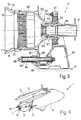
- Number 1 in Figure 4 indicates as a whole a helicopter comprising a main rotor 2 with blades 3 foldable along the body 4 of the helicopter; and a tail rotor 5 carried by a tail section 6 foldable with respect to body 4.
- tail section 6 is hinged to body 4 about a lateral axis C inclined forwards and upwards with respect to the vertical ( Figure 1) so that, when folded, tail section 6 extends laterally downwards with respect to body 4.
- Tail rotor 5 is connected to a main transmission (not shown) by a transmission line 7 (shown partly in Figure 1) defined by a first portion 7a of axis A housed in body 4, and by a second portion 7b of axis B housed in tail section 6; axes A and B being coincident when tail section 6 is in the work position.
- a transmission line 7 shown partly in Figure 1 defined by a first portion 7a of axis A housed in body 4, and by a second portion 7b of axis B housed in tail section 6; axes A and B being coincident when tail section 6 is in the work position.
- Portions 7a, 7b are each defined by a number of hollow shafts 8a, 8b in series with one another.
- Figure 1 only shows the rear end shaft 8a of portion 7a and the front end shaft 8b of portion 7b, between which, according to the present invention, a releasable coupling 10 is interposed.
- Coupling 10 substantially comprises a first coupling assembly 14 (Figure 2) connected to body 4, and a second coupling assembly 15 ( Figure 3) connected to tail section 6.
- first coupling assembly 14 comprises a support 16 connected rigidly to the structure of body 4 and integrally defining a tubular sleeve 17 of axis A, in which shaft 8a is supported and permitted to rotate by means of a double-row ball bearing 18.
- First coupling assembly 14 also comprises a hub 19 having a tubular portion 20, which is internally coaxial with shaft 8a, is locked axially inside shaft 8a, and is connected rotationally to shaft 8a by a splined coupling 21. From one end of tubular portion 20, there extend integrally a flared flange 23 having a flat annular peripheral edge 24, and a substantially conical supporting portion 25 having a projecting pin 26 of axis A.
- Flange 23 is closed at the front by a disk 29 substantially coplanar with edge 24 and having a central hole for the passage of supporting portion 25.
- Edge 24 of flange 23 is fitted rigidly with a ring gear 27 having straight cylindrical inner teeth 28; and pin 26 is fitted with a projecting orientable hollow shaft 30 of axis D. More specifically, one end 31 of shaft 30 is connected to pin 26 by a spherical joint 32 with a center P along axis A; and axis D of shaft 30, in use coincident with axis A, may be offset with respect to axis A as shown (by the dot-and-dash lines) in Figure 2.
- a gear 33 extends integrally from end 31, is housed inside ring gear 27, and comprises straight (i.e. extending along radial planes) but convex peripheral teeth 34 with a spherical profile of center P, and which mesh with inner teeth 28 of ring gear 27 to rotationally connect shaft 30 to hub 19.
- Shaft 30 is fitted in axially-sliding and angularly-integral manner with a transmission member 35 of axis D.
- member 35 substantially comprises a sleeve 36 having a tubular first end 37 sliding on a cylindrical guide surface 38 defined by an intermediate annular projection 39 of shaft 30, and a tubular second end 40 sliding on a guide ring 41 fitted by a ring nut 95 to the end 42 of shaft 30 opposite end 31.
- Sleeve 36 is connected angularly to shaft 30 by a splined coupling 43 interposed between shaft 30 and an intermediate portion 45 of sleeve 36; and coupling 43 is defined by helical teeth 46, 47 respectively inside sleeve 36 and outside shaft 30, and which slope slightly by a few degrees with respect to axis D of shaft 30.
- Transmission member 35 also comprises a gear 48 extending integrally outwards from intermediate portion 45 of sleeve 36, and having radial straight (i.e. extending along radial planes) but arc-shaped teeth 49 with a convex, substantially barrel-shaped profile tapering on the side facing second end 40 of sleeve 36.
- Teeth 49 each have an end bevel 59 for assisting engagement as described clearly later on.
- Sleeve 36 is normally maintained in a limit axial position ( Figure 2) defined by inner teeth 46 contacting guide ring 41, and by a helical spring 50 coaxial with shaft 30 and compressed between an outer intermediate shoulder 52 of sleeve 36 and an annular supporting element 51 fitted to shaft 30 and axially contacting gear 33.
- First coupling assembly 14 also comprises at the end a substantially conical, convex male lead-in element 54 having a base portion 55 fitted to sleeve 36, and a lateral wall 56, which terminates in a rounded tip 57 facing tail section 6 and has a peripheral edge 58 butt connected to gear 48 and so formed as to substantially blend lateral wall 56 with a bottom surface of teeth 49 of gear 48.
- Second coupling assembly 15 ( Figure 3) in turn comprises a supporting bracket 60 connected rigidly to the structure of tail section 6, and integrally defining an annular support 61 of axis B.
- a second transmission member 64 rotationally integral with shaft 8b and interacting, in use, with first coupling assembly 14, is fitted orientably inside support 61 by means of a bush 62 and a rolling bearing 63 cooperating mutually by means of respective spherical contact surfaces.
- transmission member 64 comprises a hub 65, which is fitted inside bearing 63, supports one end 66 of shaft 8b, and is connected angularly to end 66 by a splined coupling 67; and a cylindrical ring gear 68 projecting axially from hub 65 towards body 4, and connected integrally to hub 65 by a conical flange 69.
- Ring gear 68 comprises straight inner teeth 70, which are engaged, in use, by teeth 49 of gear 48 of first coupling assembly 14 ( Figure 1).
- a free edge 74 of ring gear 68 is fitted with a second female lead-in element 75 having a flared truncated-cone-shaped wall 76 projecting beyond ring gear 68 and defined internally by a conical surface 77 which blends with an inner surface 79 of ring gear 68.
- First and second lead-in elements 54 and 75 are conveniently made of plastic material.
- Coupling 10 also comprises a device 80 for locking tail rotor 5 when tail section 6 is folded.
- Device 80 substantially comprises a rod 84 having an axis parallel to axis B, and which is fitted in axially-sliding manner to bracket 60 of second coupling assembly 15.
- Rod 84 is fitted, in an intermediate position, with an engaging member 85 having a projection 86 which cooperates with a toothed disk 87, integral with ring gear 68, to prevent the disk from rotating.
- rod 84 comprises a push member 88, which cooperates with a mating surface 89 on a stop member 90 fitted rigidly to body 4.
- a spring 94 compressed between bracket 60 and push member 88, draws rod 84 into the axial stop position shown in Figure 3 (and by the dash line in Figure 1) in which projection 86 interacts with and engages a gap between the teeth of disk 87 to prevent the disk from rotating and so lock shaft 8b, integral with the disk, and tail rotor 5.
- Coupling 10 operates as follows.
- Figure 1 shows the work position of coupling 10 rotationally connecting portion 7a to portion 7b of transmission line 7 to the tail rotor.
- torque is transmitted from shaft 8a via splined coupling 21 to hub 19, and from hub 19 to shaft 30 via ring gear 27 and gear 33; and transmission member 35 is driven by shaft 30 via splined coupling 43.
- Gear 48 of transmission member 35 which is maintained in the limit position by spring 50, meshes with teeth 70 of ring gear 68 of transmission member 64, which in turn is angularly integral with shaft 8b.
- device 80 for locking the tail rotor is deactivated; and stop member 90 cooperates with push member 88, in opposition to spring 94, to keep rod 84 in a withdrawn position in which engaging member 85 (shown by the continuous line in Figure 1) is detached from disk 87.
- stop member 90 allows rod 84 to be moved by spring 94 into the axial stop position shown in Figure 3 (and by the dash line in Figure 1) in which projection 86 interacts with the teeth of disk 87.
- assembly 14 assumes the configuration shown partly by the dash line in Figure 2, in which shaft 30 and transmission member 35 slope downwards under their own weight in a stop position in which teeth 28 of gear 27 rest on disk 29.
- gear 48 and ring gear 68 brought into contact with each other; the engagement of respective teeth 49 and 70, cooperating telescopically with each other, being assisted by front bevels 59 of teeth 49. If the relative angular position of teeth 49 and 70 is such that teeth 49 frontally contact teeth 70, spring 50 is compressed elastically to absorb the impact, by transmission member 35 sliding axially along shaft 30, and so prevent damaging the teeth. On account of the helical shape of splined coupling 43 between transmission member 35 and shaft 30, member 35, as it slides axially, is rotated sufficiently to offset and so telescopically engage teeth 49 and 70. Spring 50 may thus restore member 35 to the limit position and ensure, in use, sufficient elastic pressure on member 35 to keep it safely coupled with second transmission member 64.
- teeth 49, 70 provides for reliable engagement of coupling assemblies 14 and 15 in any flight conditions; while teeth 49, 70 and orientable assembly of the transmission member 35 provide for compensating any misalignment of portions 7a and 7b of transmission line 7 to the tail rotor.
Landscapes
- Engineering & Computer Science (AREA)
- Mechanical Engineering (AREA)
- Aviation & Aerospace Engineering (AREA)
- Mechanical Operated Clutches (AREA)
- Transmission Devices (AREA)
- Toys (AREA)
- Retarders (AREA)
Applications Claiming Priority (2)
| Application Number | Priority Date | Filing Date | Title |
|---|---|---|---|
| IT97TO000710A IT1293676B1 (it) | 1997-08-01 | 1997-08-01 | Innesto rilasciabile per una linea di trasmissione del moto ad un rotore di coda di un elicottero. |
| ITTO970710 | 1997-08-01 |
Publications (3)
| Publication Number | Publication Date |
|---|---|
| EP0894711A2 true EP0894711A2 (de) | 1999-02-03 |
| EP0894711A3 EP0894711A3 (de) | 1999-10-27 |
| EP0894711B1 EP0894711B1 (de) | 2003-04-16 |
Family
ID=11415930
Family Applications (1)
| Application Number | Title | Priority Date | Filing Date |
|---|---|---|---|
| EP98114559A Expired - Lifetime EP0894711B1 (de) | 1997-08-01 | 1998-08-03 | Trennbare Kupplung für eine Heckrotor-Kraftübertragungsvorrichtung eines Hubschraubers |
Country Status (5)
| Country | Link |
|---|---|
| US (1) | US6050521A (de) |
| EP (1) | EP0894711B1 (de) |
| JP (1) | JP4243370B2 (de) |
| DE (1) | DE69813405T2 (de) |
| IT (1) | IT1293676B1 (de) |
Cited By (3)
| Publication number | Priority date | Publication date | Assignee | Title |
|---|---|---|---|---|
| EP1752672A1 (de) * | 2005-08-12 | 2007-02-14 | Eurocopter | Verfahren und System zur Ausrichtung, Verfahren und Antriebsvorrichtung und Flugzeug |
| CN105644778A (zh) * | 2014-11-14 | 2016-06-08 | 江西昌河航空工业有限公司 | 一种直升机应急辅助折叠和展开的方法 |
| EP3075652A1 (de) | 2015-03-31 | 2016-10-05 | Airbus Helicopters | Vorrichtung zum einklappen/ausklappen eines heckrohrs eines drehflügelflugzeugs, entsprechendes drehflügelflugzeug und entsprechendes ein- und ausklappverfahren |
Families Citing this family (14)
| Publication number | Priority date | Publication date | Assignee | Title |
|---|---|---|---|---|
| ES2151798B1 (es) * | 1998-01-09 | 2001-05-01 | Lopez Jose Luis Gomez | Autocptero, vehiculo de automocion a motor, reconvertible en aeromovi l. |
| US20070205325A1 (en) * | 2005-06-24 | 2007-09-06 | Karem Aircraft, Inc. | Separable under load shaft coupling |
| US9067677B2 (en) | 2009-12-02 | 2015-06-30 | Saab Ab | Dismountable helicopter |
| NL1039163C2 (en) * | 2011-11-11 | 2013-05-14 | Pal V Europ N V | Vehicle. |
| US10377473B2 (en) * | 2013-01-04 | 2019-08-13 | Bell Helicopter Textron Inc. | Disconnecting a rotor |
| RU2559676C2 (ru) * | 2013-08-08 | 2015-08-10 | Андрей Михайлович Трубицин | Трансмиссия вертолета |
| EP2933187B1 (de) | 2014-04-15 | 2017-01-11 | AIRBUS HELICOPTERS DEUTSCHLAND GmbH | Drehflügelflugzeug mit einem mehrholmigen Heckausleger |
| RU2636449C1 (ru) * | 2016-08-10 | 2017-11-23 | Акционерное общество "Государственный научно-исследовательский институт приборостроения", АО "ГосНИИП" | Трансмиссия вертолёта |
| CN111776211A (zh) * | 2020-07-30 | 2020-10-16 | 天津曙光天成科技有限公司 | 一种尾旋翼传动系统及无人直升机 |
| US11975825B2 (en) | 2020-11-23 | 2024-05-07 | Textron Innovations Inc. | Spline with expendable spherical alignment head |
| CN113277077A (zh) * | 2021-06-30 | 2021-08-20 | 广州极飞科技股份有限公司 | 飞行器 |
| TR2022018286A1 (tr) * | 2022-11-30 | 2024-06-21 | Tusas Tuerk Havacilik Ve Uzay Sanayii Anonim Sirketi | Bir helikopter kuyruk katlama mekanizması. |
| TR2022018277A1 (tr) * | 2022-11-30 | 2024-06-21 | Tusas Tuerk Havacilik Ve Uzay Sanayii Anonim Sirketi | Bir helikopter kuyruk katlama sistemi. |
| TR2022018273A1 (tr) * | 2022-11-30 | 2024-06-21 | Tusas Tuerk Havacilik Ve Uzay Sanayii Anonim Sirketi | Bir kuyruk katlama mekanizması. |
Family Cites Families (10)
| Publication number | Priority date | Publication date | Assignee | Title |
|---|---|---|---|---|
| US3016721A (en) * | 1960-04-14 | 1962-01-16 | Ford Motor Co | Universal joint |
| US3116896A (en) * | 1961-04-05 | 1964-01-07 | Eltra Corp | Combination helicopter-automobile |
| US3185409A (en) * | 1962-12-10 | 1965-05-25 | Hiller Aircraft Company Inc | Foldable rotary wing aircraft |
| GB1472892A (en) * | 1974-01-14 | 1977-05-11 | Westland Aircraft Ltd | Disconnectable coupling for drive shafts |
| DE3307339C2 (de) * | 1983-03-02 | 1987-02-26 | Jean Walterscheid Gmbh, 5204 Lohmar | Selbstkuppelbare Gelenkwelle |
| GB8711700D0 (en) * | 1987-05-18 | 1987-06-24 | Green P C | Mechanical coupling |
| US5186573A (en) * | 1991-09-23 | 1993-02-16 | Dana Corporation | Coupling for connecting shafts |
| US5360376A (en) * | 1993-01-13 | 1994-11-01 | United Technologies Corporation | Quick release disconnect coupling device for drive shaft segments |
| US5360476A (en) * | 1993-08-02 | 1994-11-01 | Whatcott Burton K | High impact resistant foam protectant |
| FR2727483A1 (fr) * | 1994-11-25 | 1996-05-31 | Standard Products Ind | Dispositif d'accouplement automatique |
-
1997
- 1997-08-01 IT IT97TO000710A patent/IT1293676B1/it active IP Right Grant
-
1998
- 1998-07-28 US US09/124,188 patent/US6050521A/en not_active Expired - Lifetime
- 1998-08-03 DE DE69813405T patent/DE69813405T2/de not_active Expired - Lifetime
- 1998-08-03 JP JP21917798A patent/JP4243370B2/ja not_active Expired - Fee Related
- 1998-08-03 EP EP98114559A patent/EP0894711B1/de not_active Expired - Lifetime
Non-Patent Citations (1)
| Title |
|---|
| None |
Cited By (8)
| Publication number | Priority date | Publication date | Assignee | Title |
|---|---|---|---|---|
| EP1752672A1 (de) * | 2005-08-12 | 2007-02-14 | Eurocopter | Verfahren und System zur Ausrichtung, Verfahren und Antriebsvorrichtung und Flugzeug |
| FR2889724A1 (fr) * | 2005-08-12 | 2007-02-16 | Eurocopter France | Procede et systeme de mise en coincidence, methode et dispositif d'entrainement et aeronef. |
| US7631737B2 (en) | 2005-08-12 | 2009-12-15 | Eurocopter | Method and a system for setting into coincidence, a technique, a drive device, and an aircraft |
| CN105644778A (zh) * | 2014-11-14 | 2016-06-08 | 江西昌河航空工业有限公司 | 一种直升机应急辅助折叠和展开的方法 |
| EP3075652A1 (de) | 2015-03-31 | 2016-10-05 | Airbus Helicopters | Vorrichtung zum einklappen/ausklappen eines heckrohrs eines drehflügelflugzeugs, entsprechendes drehflügelflugzeug und entsprechendes ein- und ausklappverfahren |
| FR3034397A1 (fr) * | 2015-03-31 | 2016-10-07 | Airbus Helicopters | Dispositif de repliage/depliage d'une poutre de queue d'un giravion, giravion associe et procede de repliage/depliage correspondant |
| KR20160117355A (ko) * | 2015-03-31 | 2016-10-10 | 에어버스 헬리콥터스 | 회전익기의 테일 붐을 폴딩/언폴딩하기 위한 장치, 연관된 회전익기, 및 대응하는 폴딩/언폴딩 방법 |
| US9932105B2 (en) | 2015-03-31 | 2018-04-03 | Airbus Helicopters | Device for folding/unfolding a tail boom of a rotorcraft, an associated rotorcraft, and a corresponding folding/unfolding method |
Also Published As
| Publication number | Publication date |
|---|---|
| EP0894711A3 (de) | 1999-10-27 |
| JPH11132249A (ja) | 1999-05-18 |
| EP0894711B1 (de) | 2003-04-16 |
| DE69813405D1 (de) | 2003-05-22 |
| ITTO970710A1 (it) | 1999-02-01 |
| DE69813405T2 (de) | 2004-02-12 |
| IT1293676B1 (it) | 1999-03-08 |
| JP4243370B2 (ja) | 2009-03-25 |
| US6050521A (en) | 2000-04-18 |
Similar Documents
| Publication | Publication Date | Title |
|---|---|---|
| US6050521A (en) | Releasable coupling for a helicopter tail rotor power transmission line | |
| CN106163924B (zh) | 用于飞行器起落架的驱动系统 | |
| EP0184230B1 (de) | Hinterkantenflügelklappengerät für ein Flugzeug | |
| EP1813140B1 (de) | Automatische Sperrkugelkupplung für eine Zapfwelle | |
| US2747817A (en) | Retractable landing gears | |
| EP3254955B1 (de) | Klappbare flügel und aktuatoranordnung | |
| JPH0522622B2 (de) | ||
| WO2015132481A1 (fr) | Dispositif d'attelage d'un outil tel qu'un outil agricole, sur un système de relevage d'un engin tel qu'un tracteur agricole | |
| US11009078B2 (en) | Compressible driveshaft | |
| US9932105B2 (en) | Device for folding/unfolding a tail boom of a rotorcraft, an associated rotorcraft, and a corresponding folding/unfolding method | |
| US20190338810A1 (en) | Driveshaft locking mechanism | |
| JPS6217488A (ja) | フランジ管用急速連結ユニオン | |
| US5672112A (en) | Zero clearance locking mechanism for a disconnect coupling device | |
| CN108368779A (zh) | 包括联接构件的传输机构、配备有这种机构的涡轮机和所述机构的操作方法 | |
| US11827131B2 (en) | Armrest | |
| CN108945400B (zh) | 一种小型无人机起落架锁定结构 | |
| CN110901901A (zh) | 一种起落架收放装置 | |
| US6062982A (en) | Force transmitting apparatus | |
| EP3332987A1 (de) | Lenkrollenanordnung und rollstuhl mit derselben anordnung | |
| JP2684529B2 (ja) | カップリングスリーブをカップリングピンと結合するカップリング | |
| CN117508671A (zh) | 一种空间站舱外维修用驱动杆 | |
| US20010014624A1 (en) | Telescopic mechanical transmission with angular adjustment for assembly | |
| US3132731A (en) | Pivotally disengageable coupling with indexing means | |
| GB2187820A (en) | Shaft coupling for hookes joint | |
| US20200300306A1 (en) | Rotary Power Coupler Assembly |
Legal Events
| Date | Code | Title | Description |
|---|---|---|---|
| PUAI | Public reference made under article 153(3) epc to a published international application that has entered the european phase |
Free format text: ORIGINAL CODE: 0009012 |
|
| AK | Designated contracting states |
Kind code of ref document: A2 Designated state(s): DE FR GB |
|
| AX | Request for extension of the european patent |
Free format text: AL;LT;LV;MK;RO;SI |
|
| RIN1 | Information on inventor provided before grant (corrected) |
Inventor name: REGONINI, ROBERTO |
|
| PUAL | Search report despatched |
Free format text: ORIGINAL CODE: 0009013 |
|
| AK | Designated contracting states |
Kind code of ref document: A3 Designated state(s): AT BE CH CY DE DK ES FI FR GB GR IE IT LI LU MC NL PT SE |
|
| AX | Request for extension of the european patent |
Free format text: AL;LT;LV;MK;RO;SI |
|
| RIC1 | Information provided on ipc code assigned before grant |
Free format text: 6B 64C 27/12 A, 6B 64C 1/30 B, 6F 16D 1/10 B |
|
| 17P | Request for examination filed |
Effective date: 20000403 |
|
| RAP1 | Party data changed (applicant data changed or rights of an application transferred) |
Owner name: AGUSTA S.P.A. |
|
| AKX | Designation fees paid |
Free format text: DE FR GB |
|
| 17Q | First examination report despatched |
Effective date: 20011120 |
|
| GRAH | Despatch of communication of intention to grant a patent |
Free format text: ORIGINAL CODE: EPIDOS IGRA |
|
| GRAH | Despatch of communication of intention to grant a patent |
Free format text: ORIGINAL CODE: EPIDOS IGRA |
|
| GRAA | (expected) grant |
Free format text: ORIGINAL CODE: 0009210 |
|
| AK | Designated contracting states |
Designated state(s): DE FR GB |
|
| REG | Reference to a national code |
Ref country code: GB Ref legal event code: FG4D |
|
| REF | Corresponds to: |
Ref document number: 69813405 Country of ref document: DE Date of ref document: 20030522 Kind code of ref document: P |
|
| ET | Fr: translation filed | ||
| PLBE | No opposition filed within time limit |
Free format text: ORIGINAL CODE: 0009261 |
|
| STAA | Information on the status of an ep patent application or granted ep patent |
Free format text: STATUS: NO OPPOSITION FILED WITHIN TIME LIMIT |
|
| 26N | No opposition filed |
Effective date: 20040119 |
|
| PGFP | Annual fee paid to national office [announced via postgrant information from national office to epo] |
Ref country code: DE Payment date: 20140730 Year of fee payment: 17 |
|
| PGFP | Annual fee paid to national office [announced via postgrant information from national office to epo] |
Ref country code: FR Payment date: 20140808 Year of fee payment: 17 Ref country code: GB Payment date: 20140730 Year of fee payment: 17 |
|
| REG | Reference to a national code |
Ref country code: DE Ref legal event code: R082 Ref document number: 69813405 Country of ref document: DE Representative=s name: ZENZ PATENTANWAELTE PARTNERSCHAFT MBB, DE |
|
| REG | Reference to a national code |
Ref country code: DE Ref legal event code: R119 Ref document number: 69813405 Country of ref document: DE |
|
| GBPC | Gb: european patent ceased through non-payment of renewal fee |
Effective date: 20150803 |
|
| REG | Reference to a national code |
Ref country code: FR Ref legal event code: ST Effective date: 20160429 |
|
| PG25 | Lapsed in a contracting state [announced via postgrant information from national office to epo] |
Ref country code: GB Free format text: LAPSE BECAUSE OF NON-PAYMENT OF DUE FEES Effective date: 20150803 Ref country code: DE Free format text: LAPSE BECAUSE OF NON-PAYMENT OF DUE FEES Effective date: 20160301 |
|
| PG25 | Lapsed in a contracting state [announced via postgrant information from national office to epo] |
Ref country code: FR Free format text: LAPSE BECAUSE OF NON-PAYMENT OF DUE FEES Effective date: 20150831 |