EP3075652A1 - Vorrichtung zum einklappen/ausklappen eines heckrohrs eines drehflügelflugzeugs, entsprechendes drehflügelflugzeug und entsprechendes ein- und ausklappverfahren - Google Patents
Vorrichtung zum einklappen/ausklappen eines heckrohrs eines drehflügelflugzeugs, entsprechendes drehflügelflugzeug und entsprechendes ein- und ausklappverfahren Download PDFInfo
- Publication number
- EP3075652A1 EP3075652A1 EP16161722.0A EP16161722A EP3075652A1 EP 3075652 A1 EP3075652 A1 EP 3075652A1 EP 16161722 A EP16161722 A EP 16161722A EP 3075652 A1 EP3075652 A1 EP 3075652A1
- Authority
- EP
- European Patent Office
- Prior art keywords
- power transmission
- folding
- unfolding
- movable portion
- shaft
- Prior art date
- Legal status (The legal status is an assumption and is not a legal conclusion. Google has not performed a legal analysis and makes no representation as to the accuracy of the status listed.)
- Granted
Links
Images


Classifications
-
- B—PERFORMING OPERATIONS; TRANSPORTING
- B64—AIRCRAFT; AVIATION; COSMONAUTICS
- B64C—AEROPLANES; HELICOPTERS
- B64C1/00—Fuselages; Constructional features common to fuselages, wings, stabilising surfaces or the like
- B64C1/30—Parts of fuselage relatively movable to reduce overall dimensions of aircraft
-
- B—PERFORMING OPERATIONS; TRANSPORTING
- B64—AIRCRAFT; AVIATION; COSMONAUTICS
- B64C—AEROPLANES; HELICOPTERS
- B64C1/00—Fuselages; Constructional features common to fuselages, wings, stabilising surfaces or the like
- B64C1/06—Frames; Stringers; Longerons ; Fuselage sections
- B64C1/061—Frames
- B64C1/063—Folding or collapsing to reduce overall dimensions, e.g. foldable tail booms
-
- B—PERFORMING OPERATIONS; TRANSPORTING
- B64—AIRCRAFT; AVIATION; COSMONAUTICS
- B64C—AEROPLANES; HELICOPTERS
- B64C27/00—Rotorcraft; Rotors peculiar thereto
- B64C27/04—Helicopters
- B64C27/08—Helicopters with two or more rotors
-
- B—PERFORMING OPERATIONS; TRANSPORTING
- B64—AIRCRAFT; AVIATION; COSMONAUTICS
- B64C—AEROPLANES; HELICOPTERS
- B64C27/00—Rotorcraft; Rotors peculiar thereto
- B64C27/82—Rotorcraft; Rotors peculiar thereto characterised by the provision of an auxiliary rotor or fluid-jet device for counter-balancing lifting rotor torque or changing direction of rotorcraft
-
- B—PERFORMING OPERATIONS; TRANSPORTING
- B64—AIRCRAFT; AVIATION; COSMONAUTICS
- B64C—AEROPLANES; HELICOPTERS
- B64C27/00—Rotorcraft; Rotors peculiar thereto
- B64C27/04—Helicopters
- B64C27/06—Helicopters with single rotor
Definitions
- the present invention relates to the field of rotorcraft equipped in general with one or more power units, a main transmission gearbox, at least one main power transmission shaft driving in rotation a main rotor capable of producing at least the lift of the rotorcraft, at least one rear power transmission shaft and at least one rear power transmission box which drives in rotation a rear rotorcraft rotor for controlling the movements of the rotorcraft, in particular for a helicopter, around a yaw axis.
- such a rotorcraft may also include an intermediate power transmission box arranged at a tail boom on a power transmission line, upstream of the rear power transmission box and downstream of the power transmission line. main gearbox of power.
- Such an intermediate power transmission box thus forms an angle gearing called “power transmission angle transmission” and is used when the axis of rotation of the rear rotor is offset vertically with respect to a longitudinal direction of the beam.
- tail of the rotorcraft for example above a plane in which is inscribed the rear power transmission shaft.
- the invention relates more particularly to a reversible folding / unfolding device intended to equip the power transmission rear shaft.
- such a folding / unfolding device is intrinsically arranged at a junction between two portions of a rotorcraft tail boom.
- a first portion of the tail boom is integral with the fuselage of the rotorcraft and fixed relative thereto.
- a second portion of the beam tail is rotatable about an axis relative to the fixed portion.
- Such folding / unfolding device thus reduces the overall size of the rotorcraft when the movable portion of the tail boom is arranged in a folded position.
- This folding / unfolding device makes it possible to make a tail boom foldable when the rotors of the rotorcraft are stopped and thus improves the compactness of the rotorcraft during their transport or storage in narrow and cramped compartments such as in particular bunkers of ships or cargo planes and hangars.
- the folding / unfolding of the tail boom of a rotorcraft is performed around an axis of rotation inscribed substantially in a transverse plane perpendicular to a longitudinal direction of the power transmission shaft capable of transmitting a motor torque to the rotor back of the rotorcraft.
- such a horizontal stabilizer emerges substantially radially from a longitudinal direction of the tail boom and consists of a horizontal transverse tail or substantially horizontal, or inclined.
- such a horizontal stabilizer may be arranged asymmetrically or symmetrically on either side of the tail boom.
- the movable portion can not fall back against the fixed portion with an opening angle of 180 degrees. Due to the horizontal stabilizer, and mechanical interferences between the two resulting portions of the tail boom, the angle of folding / unfolding around the axis of rotation is at most 120 degrees. This limitation of the folding / unfolding angle then gives the rotorcraft a large width which may even be greater than the width of the cockpit.
- the overall length can be reduced but the overall width can in some cases be increased.
- the power transmission rear shaft must be mechanically uncoupled or decoupled to be separated into two parts.
- Such a decoupling action is generally obtained by means of a clutch movable in translation along the longitudinal direction of the power transmission rear shaft.
- the patent EP 0 894 711 discloses such a folding / unfolding device comprising in particular a sliding clutch in translation along a longitudinal direction parallel to the power transmission rear shaft.
- the tail boom repositioning when closing the movable portion of the tail boom to ensure proper alignment of all rear power transmission shafts.
- the coupling / uncoupling function is decorrelated from the necessary locking of the tail boom in the unfolded coupling position, that is to say in the flight configuration of the rotorcraft.
- the mechanical coupling is ensured by a conical guide element and teeth having a profile arcuate.
- This conical guide further comprises elastic axial support means for axially supporting the coincidence of the teeth when the movable portion of the tail beam is engaged opposite the fixed portion.
- the cone of the fixed part At the level of the power transmission rear shaft, the cone of the fixed part has a large backward stroke and allows self-centering with the receiving cone of the moving part. The cone of the fixed part then comes into contact with the internal stop of the receiving cone of the moving part. When the total unfolding of the tail boom is carried out, the receiving cone moves back under the impulse of the cone of the fixed part up to its point of engagement making it possible to couple the power transmission.
- such a folding / unfolding device requires having a certain recoil at the rear power transmission shaft and prohibits its installation in the immediate vicinity of a rear power transmission box or, in some cases where the rotorcraft is equipped, in the immediate vicinity of an intermediate power transmission box.
- this type of device also limits the angle of folding / unfolding of the movable portion relative to the fixed portion of the tail boom.
- this technique of folding / unfolding the tail boom requires a folding / unfolding device with complex conical members mechanically to achieve, heavy and requiring additional maintenance operations to ensure the proper operation and level of wear of the various moving parts constituting such devices.
- the present invention therefore aims to provide a device to overcome the limitations mentioned above.
- Such a device thus aims to improve the compactness in length and width of a rotorcraft having a foldable tail beam for transport and / or storage.
- Another object of the invention is to allow the installation of the folding / unfolding device on the tail boom, and this at any location of a power transmission rear shaft.
- a folding / unfolding device is more generally positioned on the tail boom at a rear power transmission shaft upstream of a rear power transmission box and downstream of a box. main power transmission to ensure a maximum folding / unfolding angle for the moving portion of the tail boom.
- the invention therefore relates to a device for folding / unfolding a tail boom arranged on this tail beam at a rear power transmission shaft upstream of a rear power transmission box and downstream of a main power transmission box mechanically connected to at least one engine of the rotorcraft.
- the power transmission rear shaft is able to transmit a driving torque and to drive in rotation a rear rotor of the rotorcraft.
- This folding / unfolding device is remarkable in that the disengagement / coupling means are motorized and can be actuated independently of the rotary means in order firstly to mechanically uncouple the two parts of the same power transmission rear shaft beforehand. the relative displacement in rotation corresponding to the folding of the movable portion relative to the fixed portion of the tail boom and, secondly, mechanically coupling the two parts of the same rear power transmission shaft after the corresponding relative rotational displacement unfolding the movable portion relative to the fixed portion of the tail boom.
- the means of uncoupling / coupling may comprise at least one actuator which may be chosen in particular from the group comprising pneumatic actuators, hydraulic or electrical.
- the disengagement / coupling means allow to move in translation a coupling member such as a clutch in a direction substantially parallel to a longitudinal direction of the power transmission rear shaft.
- a coupling member such as a clutch
- Such a clutch generally has teeth emerging radially outwardly, the teeth of this clutch being intended to cooperate with complementary grooves formed in a fixed bell integral with another part of the rear power transmission shaft.
- a rotorcraft may comprise an intermediate power transmission box arranged at a tail boom on a power transmission line, upstream of the rear power transmission box and downstream of the main power transmission box.
- the device for folding / unfolding a tail boom according to the invention is then more precisely arranged on this tail beam at a rear power transmission shaft upstream of a box of power transmission intermediate and downstream of a main power transmission box mechanically connected to at least one engine of the rotorcraft.
- the folding / unfolding device may comprise unlocking / locking means in unfolded working position of the movable portion of the tail boom with respect to the fixed portion of the tail boom.
- the unlocking / locking means prevent inadvertent folding of the tail boom.
- Such locking / unlocking means thus realize a blocking in unfolded position of the connection in rotation between the movable portion and the fixed portion of the tail boom, this locking being necessary in flight configuration of the rotorcraft.
- the locking / unlocking means are advantageously motorized and can be controlled automatically by the pilot or any other person authorized to control the folding / unfolding of the tail boom of the rotorcraft such as a mechanic for example.
- the uncoupling / coupling means and the unlocking / locking means may be actuated by a common actuator.
- a single actuator and therefore the same control setpoint of this actuator, can both mechanically uncouple / couple the power transmission rear shaft and unlock the relative rotational movement between the movable portion and the fixed portion of the tail boom.
- the disengagement / coupling means may comprise a first spring biasing means biased in compression and whose free ends respectively bear on a frame of the fixed portion and on a flat face of a translationally movable clutch. in a direction parallel to a longitudinal direction of the power transmission rear shaft and the unlocking / locking means may comprise a second resilient biasing means biased in compression and whose free ends respectively bear on the frame of the fixed portion and on a flat face of a rod of the unlocking / locking means.
- the uncoupling / coupling means and the unlocking / locking means may each automatically return to a safe rest position intended to prevent any risk of accident to the operator. rotorcraft.
- the first elastic return means makes it possible to immobilize the uncoupling / coupling means in a coupling position guaranteeing a mechanical power transmission between the two parts of the power transmission rear shaft.
- the second elastic return means for its part immobilizes the unlocking / locking means in a locking position of the relative rotation between the movable portion and the fixed portion of the tail boom.
- the first elastic return means may make it possible to exert a first return force on the clutch and the second elastic return means may make it possible to exert a second restoring force on the rod of the unlocking / locking means, the first return force being lower than the second restoring force.
- the second restoring force exerted by the second elastic return means makes it possible to guarantee that the rod of the unlocking / locking means remains in a so-called "normally output" rest position in the event of power failure of the actuator .
- the device may advantageously comprise a mechanical connecting member allowing simultaneous actuation of the uncoupling / coupling means and the unlocking / locking means with the common actuator.
- such a mechanical connecting member makes it possible to transmit the movement of the common actuator simultaneously to the uncoupling / coupling means and to the unlocking / locking means.
- the mechanical connecting member may comprise at least one connecting rod, at least one angle gearbox called “link angle transmission” comprising at least one degree of freedom in rotation with respect to the frame and a pusher for exerting a thrust force on the flat face of the clutch, the free ends of the connecting rod being respectively arranged in ball joint connection with a free end of the rod and a free end of a lever arm of the link angle transmission, the mechanical link member allowing the common actuator to move in translation the movable clutch in a direction parallel to the longitudinal direction of the power transmission rear shaft.
- link angle transmission comprising at least one degree of freedom in rotation with respect to the frame and a pusher for exerting a thrust force on the flat face of the clutch
- the common actuator can directly perform a displacement in translation of a rod of the unlocking / locking means in a first direction of translation.
- the link rod and the link angle transmission make it possible to transform the translational movement of the actuator into a rotational movement of the link angle transmission with respect to the frame of the fixed portion of the link beam. tail.
- the pusher of the connecting angle deflection makes it possible to transform the rotation of the link angle transmission into a translation movement of the dog in a second direction corresponding to the direction parallel to the longitudinal direction of the link. rear power transmission shaft.
- the mechanical link member may comprise at least one protrusion adapted to control the displacement in translation of a clutch, such an excrescence being arranged in sliding connection with a frame of the fixed portion of the tail boom and having a free end arranged in annular linear connection with a free end of a rod, such a rod being arranged in helical connection with the frame to transform the translational movement of at least one finger of the actuator in a combined movement of rotation and translation of the rod relative to the frame.
- a clutch such an excrescence being arranged in sliding connection with a frame of the fixed portion of the tail boom and having a free end arranged in annular linear connection with a free end of a rod, such a rod being arranged in helical connection with the frame to transform the translational movement of at least one finger of the actuator in a combined movement of rotation and translation of the rod relative to the frame.
- the common actuator can directly perform a translational movement of a rod of the unlocking / locking means in a first direction of translation.
- the helical connection makes it possible to transform the translation movement of the actuator into a rotational and translational movement of the rod with respect to the frame of the fixed portion of the tail boom.
- the annular linear connection with the protrusion and the slide connection between the protrusion and the frame make it possible to transform the rotational movement of the rod into a translation movement of the clutch in a second corresponding direction. in the direction parallel to the longitudinal direction of the power transmission rear shaft.
- the disengagement / coupling means may comprise a first actuator and the unlocking / locking means may comprise a second actuator separate from the first actuator.
- the uncoupling / coupling means and the unlocking / locking means may be actuated independently simultaneously or one after the other, the disengagement / coupling means then being actuated before the means unlocking / locking. In this way, it avoids any risk of folding the tail boom with a rear power transmission shaft still coupled between its fixed part and its moving part.
- the rotary means may comprise an axis of rotation inclined by a predetermined angle ⁇ with respect to a plane P perpendicular to a longitudinal direction of the power transmission rear shaft, a said predetermined angle ⁇ being between 20 degrees and 30 degrees.
- Such a predetermined angle of inclination ⁇ may in particular be chosen equal to 26 degrees and then allows folding to be carried out of the tail boom with an opening angle of about 170 degrees.
- the present invention also relates to a rotorcraft equipped with a rear rotor arranged at a tail boom, the rear rotor being rotated by means of at least one engine and a rear shaft power transmission and the tail boom having a portion movable in rotation with respect to a fixed portion between two distinct end positions, namely an unfolded working position allowing the power transmission rear shaft to transmit a torque to the rear rotor and a folded rest position to reduce the overall length of the rotorcraft when the engine, the rear power transmission shaft and the rear rotor are stopped.
- the rotorcraft is characterized in that it comprises a device for folding / unfolding a tail boom as previously described.
- such a rotorcraft comprises, at the level of a tail boom, motorized disengagement / coupling means making it possible to uncouple / mechanically couple the power transmission rear shaft prior to the relative displacement in rotation of the movable portion of the tail boom with respect to the fixed portion.
- This rotorcraft thus has an optimal size in length and width, in particular to facilitate its transport or storage in a boat, an airplane or in a hangar.
- the invention relates to a method of folding / unfolding a rotorcraft tail boom comprising at least one rear rotor.
- a rear rotor is thus rotated by means of at least one motor and at least one rear power transmission shaft.
- Such folding / unfolding method is implemented when the engine, the power transmission rear shaft and the rear rotor are respectively stopped.
- each of the actions consisting of uncoupling / coupling the two parts of this same power transmission rear shaft and rotating the mobile portion of the tail boom about an axis of rotation is dissociated and rendered independent.
- the two parts of the same rear transmission shaft can be mechanically uncoupled / coupled.
- power via motorized disengagement / coupling means for axially translational movement of a clutch relative to a first portion of the power transmission rear shaft in a longitudinal direction of the power transmission rear shaft, the dog clutch being able to uncouple / mate with a complementary shaped bell integral with a second portion of the power transmission rear shaft.
- the uncoupling / coupling between the two parts of the power transmission rear shaft is controlled by independently actuating the displacement in translation of the dog relative to the rotational displacement of the mobile portion of the tail boom by relative to the fixed portion.
- the motorized decoupling / coupling means may therefore be actuated prior to the third folding step of the movable portion and subsequent to the fourth unfolding step of the movable portion.
- the first step can be performed simultaneously with the second unlocking step in the unfolded working position of the movable portion relative to the fixed portion, and likewise, the fifth step can be performed simultaneously with the sixth locking step in position. unfolded work of the movable portion relative to the fixed portion.
- the second step unlocking can also be performed before or after the first step of mechanical disconnection of the two parts of the same power transmission rear shaft.
- the two parts of the same power transmission rear shaft can be mechanically uncoupled / coupled and the mobile portion of the tail boom can be unlocked / locked in the position unfolded working with a single actuator.
- the common actuator is able to perform simultaneously the uncoupling / mechanical coupling of the two parts of the power transmission rear shaft and the unlocking / locking in the unfolded working position of the movable portion relative to the fixed portion.
- a second embodiment of the folding / unfolding method it is possible to uncouple / mechanically couple the two parts of the same power transmission rear shaft with a first actuator and the mobile portion of the tail boom can be unlocked / locked in the unfolded working position with a second actuator separate from the first actuator.
- the invention relates to a device for folding / unfolding a rotorcraft tail boom.
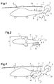
- the rotorcraft 4 comprises a folding / unfolding device 1 arranged at a tail boom 5.
- a folding / unfolding device 1 comprises rotary means 125 allowing in particular to move in a rotational movement a movable portion 6 of the tail boom 5 supporting a rear rotor 3.
- such a rotational movement takes place around an axis of rotation 22 inclined at an angle ⁇ with respect to a plane P perpendicular to a longitudinal direction parallel to a power transmission rear shaft for transmitting a signal.
- an angle ⁇ is advantageously between 20 degrees and 30 degrees and may more particularly be equal to 26 degrees in order to guarantee a maximum folding / unfolding angle of the movable portion relative to the fixed portion 7 of the tail boom 5.
- a folding / unfolding angle ⁇ / - ⁇ may advantageously have a maximum amplitude of about 170 degrees.
- the movable portion 6 of the tail boom 5 may comprise a horizontal stabilizer 13, for example of the horizontal tail type, adapted to be positioned below the fixed portion 7 of the tail boom 5.
- the angle of folding / unfolding ⁇ / - ⁇ corresponds, in top view, to an opening angle of the movable portion 6 relative to the fixed portion 7 of tail beam 5.
- the rotary means 125 make it possible to move the movable portion 6 in rotation between two end positions 20, 21 respectively corresponding to an unfolded working position 20 and a folded rest position 21 making it possible to reduce the overall length of the rotorcraft 4.
- the blades 14 of the rear rotor 3 do not touch the ground.
- the folding / unfolding device 1, 71, 81, 11 also comprises motorized uncoupling / coupling means 8, 108, 118, 18 for mechanically uncoupling / coupling two parts 201-211-271-281, 202- 212-272-282 of the same power transmission rear shaft 2, 72, 82, 12 of the rear rotor 3 before actuating the rotary means 125 and thus to fold / unfold the movable portion 6 of the beam tail 5.
- the folding / unfolding device 1, 71, 81, 11 can also comprise unlocking / locking means 9, 109, 119, 19 for immobilizing the movable portion 6 in the unfolded working position 21.
- such a folding / unfolding device 1, 71, 81, 11 may also comprise means of "locking", not shown, for immobilizing the movable portion 6 in the folded rest position 20.
- the uncoupling / coupling means 8, 108, 118, 18 and the unlocking / locking means 9, 109, 119, 19 may be formed according to different embodiments to allow the mechanical coupling / uncoupling of the two. parts 201-271-281-211, 202-272-282-212 of the power transmission rear shaft 2, 72, 82, 12 independently of the rotational movement of the movable portion 6.
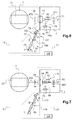
- the uncoupling / coupling means 8 and the unlocking / locking means 9 may comprise a common actuator 10 such as a hydraulic cylinder, pneumatic or electrical.
- This common actuator 10 makes it possible to move two fingers 27 arranged on either side of the body of the actuator 10 in two different directions. Such fingers 27 each cooperate with fittings or hinges 33 and thereby perform the locking / unlocking function. of the movable portion 6 in unfolded position 20 to prevent unintentional opening of the tail boom 5.
- one of the two fingers 27 also makes it possible to drive and translate a rod 26 to translate the translational movement produced by the actuator 10 to the disengagement means. 8. To do this, the displacement in translation of the rod 26 is transmitted to a connecting member 30 and the coupling / coupling means 8. Such a rod 26 is thus arranged coaxially with the fingers 27 of the actuator 10.
- the connecting member 30 comprises meanwhile at least one rod 31 and at least one connecting angle of reference 32 for changing the direction of displacement in translation in a direction parallel to a longitudinal direction 25 of the 2.
- the direction of displacement in translation of the fingers 27 is oriented parallel to the axis of rotation between the movable portion 6 and the fixed portion 7 and is therefore inclined at an angle ⁇ with respect to a plane P perpendicular to the longitudinal direction 25 of the power transmission rear shaft 2.
- the common actuator 10 is arranged in a locking position of the movable portion 6 relative to the fixed portion 7 corresponding to the output of the fingers 27 of the body of the actuator 10.
- Activation of the actuator 10 in this locking position shown in FIG. figure 4 allows on the one hand, to decompress a first elastic return means 28 acting on a clutch 24 movable in translation in the longitudinal direction 25 of the rear power transmission shaft 2, and secondly, to compress a second means resilient return 29.
- the first elastic return means 28 is in fact stressed in compression between a flat face 36 of the dog clutch 24 and a frame 35 integral with the fixed portion 7 of the tail beam.
- the force exerted by the actuator 10 to reach this locking position is advantageously greater than the compression force exerted by the second elastic return means 29 on the rod 26.
- the second elastic return means 29 is in turn stressed in compression between a flat face 38 of the rod 26 and the frame 35.
- a motor torque from the motor 124 and a main power transmission box 123 can then be transmitted between the parts 201 and 202 of the power transmission rear shaft 2 to a rear power transmission box 23 and a rear rotor 3.
- the engine torque is transmitted by the part 201 to the clutch 24 then teeth of the clutch 24 cooperating with grooves of complementary shape formed in a bell 34 transmit the motor torque to the bell 34 integral with the portion 202 of the power transmission rear shaft 2.
- the fingers 27 remain in the "locking output" position in order to guaranteeing that the movable portion 6 remains in its unfolded extreme working position 20.
- the second elastic restoring force exerted by the second elastic return means 29 is chosen to be greater than the first elastic return force exerted by the first elastic return means 28.
- the connecting angle of return 32 may include a lever arm 41 in particular to obtain a reduction of the force produced by the second elastic return means.
- the lever arm 41 thus makes it possible to obtain a second elastic return force greater than the first force with first 28 and second 29 elastic return means of the same stiffness.
- the rod 31 of the mechanical connecting member 30 is arranged at its two free ends in ball joint connection, on the one hand, with a free end 40 of the rod 26 and, on the other hand, with the lever arm 41 of the connecting angle gear 32.
- a connecting angle gear 32 further includes at least one rotational degree of freedom arranged at a link 42 with the frame 35 of the fixed portion 7
- Such a link 42 is therefore selected from the group comprising the pivot links that is to say having a degree of freedom in rotation, the finger-ball joints that is to say having two degrees of freedom in rotation and the ball joints that is that is, with three degrees of freedom in rotation.
- the rotational movement transmitted to the connecting angle return 32 makes it possible to move a pusher 39 in point or linear contact with a flat face 43 of the clutch 24 opposite to the flat face 36 of support of the first elastic return means 28.
- the pusher 39 thus makes it possible to move the clutch 24 in translation along the longitudinal direction 25 of the power transmission rear shaft 2.
- the mechanical connecting member 130, 131 of the folding / unfolding device 71, 81 may be in a form different from that presented to the Figures 4 and 5 .
- the mechanical linkage member 130, 131 makes it possible to move the dog clutch 74, 84 in translation in a direction parallel to the power transmission rear shaft 72, 82 by means of a single actuator 70, 80 as in FIGS. Figures 4 and 5 .
- the mechanical connecting member 130, 131 comprises a protrusion 79, 89 arranged in sliding connection 75 with the frame 35.
- a free end of the protrusion 79, 89 is arranged in annular linear connection 78 with a free end of a rod 126.
- the fingers 77 form with the hinges 73 the unlocking / locking means 109, 119 of the folding / unfolding device 71, 81. They also make it possible to translate the rod 126, which is also arranged in a helical connection 76, with the chassis. 35.
- the disengagement / coupling means 108 comprise the clutch 74 formed monolithically with the protrusion 79.
- the disengagement / coupling means 118 comprise the dog clutch 84 and the protrusion 79 disjoined from one another.
- the protrusion 89 is integral with a fork 83 movable in translation relative to the power transmission rear shaft 82 and the claw 84 in a direction parallel to the longitudinal direction of the rear transmission shaft. power 82.
- an elastic return means 85 may be biased in compression and arranged between the clutch 84 and the fork 83 so as to secure the holding in the coupled position of the clutch 84 with the bell 34 secured to the portion 271 of the clutch shaft. Power transmission 72.
- a bell 34 thus constitutes a motor torque receiving member of the folding / unfolding device 71.
- the disengagement / coupling means 108, 118 represented here are motorized and can be actuated independently of the rotary means 125 to enable the two parts 271-281, 272-282 of the power transmission rear shaft 72, 82 to be mechanically uncoupled before the relative displacement in rotation of the movable portion 6 is achieved of the tail boom relative to the fixed portion 7 of the tail boom 5.
- the disengagement / coupling means 18 comprise a first independent actuator 60 and the unlocking / locking means 19 comprise a second actuator 61 distinct from the first actuator 60.
- such a third embodiment makes it possible to individually independently actuate the uncoupling / coupling means 18 and the unlocking / locking means 19 before the rotary means 125.
- a finger 62 of the actuator 60 can directly push a flat face 63 of the clutch 64 to perform the translational movement of the dog 64 relative to the power transmission rear shaft 12 and thus the coupling / uncoupling between the two parts 211, 212 of the power transmission rear shaft 12.
- a resilient biasing means 68 biased in compression then allows to automatically couple the clutch 64 with the bell 34 arranged next.
- Such an elastic return means 68 is for example arranged between a flat face 66 of the frame 35 and a flat face 65 of the dog 64 opposite the flat face 63.
- the rotation of the movable portion 6 relative to the fixed portion 7 can be performed manually by an operator such as a mechanic or automatically by means of a specific actuator not shown in FIGS. Figures 4 to 8 .
- the invention also relates to a folding / unfolding method 90 of a rear power transmission shaft 2, 72, 82, 12 of a rear rotorcraft rotor 3 4.
- Such a rear rotor 3 is rotated by means of at least one engine 124 and a rear power transmission shaft 2, 72, 82, 12 and is arranged at a tail boom 5.
- the folding / unfolding method 90 further comprises a first step 91 of mechanically uncoupling two parts of the same power transmission rear shaft.
- Such a method 90 also comprises a third folding step 92 consisting of moving in a rotational movement of an angle ⁇ the movable portion 6 of a tail boom 5 with respect to the fixed portion 7 of a tail boom 5 Such folding is used to allow the storage or transport of the rotorcraft 4 thus reducing at least its overall length.
- the method 90 then comprises a fourth unfolding step 93 of moving in a rotational movement an angle - ⁇ the movable portion 6 of a tail boom 5 relative to the fixed portion 7 of a tail boom 5.
- Such unfolding is used when the rotorcraft 4 must be put into operation and used once storage or transport completed.
- such a method 90 comprises a fifth step 94 of mechanically coupling the two parts of the same power transmission rear shaft, especially when it is desired to use the rotorcraft 4.
- the third and fourth steps 92, 93 can be performed manually by an operator or automatically via a specific hydraulic, pneumatic or electrical actuator for pivoting the movable portion of the tail boom relative to the fixed portion.
- the first step 91 consisting in mechanically uncoupling the two parts of this power transmission rear shaft is implemented independently.
- Such a first step 91 is motorized or automated and can advantageously be executed simultaneously with a second unlocking step 95 of unlocking the mobile portion of the tail boom when the latter is arranged in an unfolded working position 20.
- the fifth step 94 consisting of mechanically coupling the two parts of this power transmission rear shaft is implemented independently.
- a fifth step 94 is motorized or automated and can advantageously be performed simultaneously with a sixth locking step 96 consisting of locking the mobile portion of the tail boom when it is arranged in an unfolded working position 20.
- the first step 91 and the second unlocking step 95 can be implemented by various means corresponding to different embodiments.
- the first step 91 and the second unlocking step 95 can be performed by means of a common actuator 10.
- the first step 91 can be performed by means of a first actuator 60 and the second unlocking step 95 can be performed by means of a second actuator 61 different from the first actuator 60.
- the fifth step 94 of mechanically coupling the two parts of the same power transmission rear shaft and the sixth locking step 96 can be implemented by various means corresponding to different embodiments but correspond to the means for setting implementing the first step 91 and the second unlocking step 95.
Landscapes
- Engineering & Computer Science (AREA)
- Mechanical Engineering (AREA)
- Aviation & Aerospace Engineering (AREA)
- Agricultural Machines (AREA)
- Jib Cranes (AREA)
- Toys (AREA)
Applications Claiming Priority (1)
| Application Number | Priority Date | Filing Date | Title |
|---|---|---|---|
| FR1500642A FR3034397B1 (fr) | 2015-03-31 | 2015-03-31 | Dispositif de repliage/depliage d'une poutre de queue d'un giravion, giravion associe et procede de repliage/depliage correspondant |
Publications (2)
| Publication Number | Publication Date |
|---|---|
| EP3075652A1 true EP3075652A1 (de) | 2016-10-05 |
| EP3075652B1 EP3075652B1 (de) | 2018-11-21 |
Family
ID=54199707
Family Applications (1)
| Application Number | Title | Priority Date | Filing Date |
|---|---|---|---|
| EP16161722.0A Active EP3075652B1 (de) | 2015-03-31 | 2016-03-22 | Vorrichtung zum einklappen/ausklappen eines heckauslegers eines drehflügelflugzeugs, entsprechendes drehflügelflugzeug und entsprechendes ein- und ausklappverfahren |
Country Status (4)
| Country | Link |
|---|---|
| US (1) | US9932105B2 (de) |
| EP (1) | EP3075652B1 (de) |
| KR (1) | KR101871929B1 (de) |
| FR (1) | FR3034397B1 (de) |
Cited By (3)
| Publication number | Priority date | Publication date | Assignee | Title |
|---|---|---|---|---|
| CN111806682A (zh) * | 2020-06-19 | 2020-10-23 | 中国科学院地理科学与资源研究所 | 无人机复飞方法 |
| CN111806680A (zh) * | 2020-06-19 | 2020-10-23 | 中国科学院地理科学与资源研究所 | 无人机复飞装置及无人机 |
| CN113848046A (zh) * | 2021-09-08 | 2021-12-28 | 湖南航天机电设备与特种材料研究所 | 用于测试折叠翼飞行器翼面展开同步性的测试装置 |
Families Citing this family (4)
| Publication number | Priority date | Publication date | Assignee | Title |
|---|---|---|---|---|
| US10112697B2 (en) * | 2015-05-11 | 2018-10-30 | Sikorsky Aircraft Corporation | Aircraft with thrust vectoring tail |
| US10513332B2 (en) * | 2015-10-05 | 2019-12-24 | Sikorsky Aircraft Corporation | Tiltwing aircraft |
| CN107082113A (zh) * | 2017-06-09 | 2017-08-22 | 四川雷神空天科技有限公司 | 可折叠连接装置及所应用的无人飞行器 |
| CN112238948A (zh) * | 2020-10-16 | 2021-01-19 | 中国直升机设计研究所 | 一种快卸式直升机尾传动轴组件 |
Citations (5)
| Publication number | Priority date | Publication date | Assignee | Title |
|---|---|---|---|---|
| US4245801A (en) | 1979-02-15 | 1981-01-20 | United Technologies Corporation | Tail rotor control cable-pylon fold accommodation |
| US5360376A (en) | 1993-01-13 | 1994-11-01 | United Technologies Corporation | Quick release disconnect coupling device for drive shaft segments |
| DE19647166A1 (de) | 1995-11-16 | 1997-05-22 | Sikorsky Aircraft Corp | Spielfreie Verriegelungsvorrichtung für eine Trenn-Kopplungsvorrichtung |
| EP0894711A2 (de) | 1997-08-01 | 1999-02-03 | FINMECCANICA S.p.A. | Trennbare Kupplung für eine Heckrotor-Kraftübertragungsvorrichtung eines Hubschraubers |
| KR100692237B1 (ko) | 2006-08-14 | 2007-03-12 | 원신 스카이텍 주식회사 | 폴딩식 테일붐대 |
Family Cites Families (1)
| Publication number | Priority date | Publication date | Assignee | Title |
|---|---|---|---|---|
| GB1472892A (en) * | 1974-01-14 | 1977-05-11 | Westland Aircraft Ltd | Disconnectable coupling for drive shafts |
-
2015
- 2015-03-31 FR FR1500642A patent/FR3034397B1/fr active Active
-
2016
- 2016-03-22 EP EP16161722.0A patent/EP3075652B1/de active Active
- 2016-03-29 US US15/083,568 patent/US9932105B2/en active Active
- 2016-03-31 KR KR1020160039154A patent/KR101871929B1/ko active Active
Patent Citations (5)
| Publication number | Priority date | Publication date | Assignee | Title |
|---|---|---|---|---|
| US4245801A (en) | 1979-02-15 | 1981-01-20 | United Technologies Corporation | Tail rotor control cable-pylon fold accommodation |
| US5360376A (en) | 1993-01-13 | 1994-11-01 | United Technologies Corporation | Quick release disconnect coupling device for drive shaft segments |
| DE19647166A1 (de) | 1995-11-16 | 1997-05-22 | Sikorsky Aircraft Corp | Spielfreie Verriegelungsvorrichtung für eine Trenn-Kopplungsvorrichtung |
| EP0894711A2 (de) | 1997-08-01 | 1999-02-03 | FINMECCANICA S.p.A. | Trennbare Kupplung für eine Heckrotor-Kraftübertragungsvorrichtung eines Hubschraubers |
| KR100692237B1 (ko) | 2006-08-14 | 2007-03-12 | 원신 스카이텍 주식회사 | 폴딩식 테일붐대 |
Cited By (6)
| Publication number | Priority date | Publication date | Assignee | Title |
|---|---|---|---|---|
| CN111806682A (zh) * | 2020-06-19 | 2020-10-23 | 中国科学院地理科学与资源研究所 | 无人机复飞方法 |
| CN111806680A (zh) * | 2020-06-19 | 2020-10-23 | 中国科学院地理科学与资源研究所 | 无人机复飞装置及无人机 |
| CN111806680B (zh) * | 2020-06-19 | 2023-09-12 | 中国科学院地理科学与资源研究所 | 无人机复飞装置及无人机 |
| CN111806682B (zh) * | 2020-06-19 | 2023-10-03 | 中国科学院地理科学与资源研究所 | 无人机复飞方法 |
| CN113848046A (zh) * | 2021-09-08 | 2021-12-28 | 湖南航天机电设备与特种材料研究所 | 用于测试折叠翼飞行器翼面展开同步性的测试装置 |
| CN113848046B (zh) * | 2021-09-08 | 2023-11-24 | 湖南航天机电设备与特种材料研究所 | 用于测试折叠翼飞行器翼面展开同步性的测试装置 |
Also Published As
| Publication number | Publication date |
|---|---|
| EP3075652B1 (de) | 2018-11-21 |
| US9932105B2 (en) | 2018-04-03 |
| KR20160117355A (ko) | 2016-10-10 |
| KR101871929B1 (ko) | 2018-06-27 |
| US20160332719A1 (en) | 2016-11-17 |
| FR3034397A1 (fr) | 2016-10-07 |
| FR3034397B1 (fr) | 2017-03-31 |
Similar Documents
| Publication | Publication Date | Title |
|---|---|---|
| EP3075652B1 (de) | Vorrichtung zum einklappen/ausklappen eines heckauslegers eines drehflügelflugzeugs, entsprechendes drehflügelflugzeug und entsprechendes ein- und ausklappverfahren | |
| EP2042427B1 (de) | Einklappbares Trittbrett eines Fahrzeugs und mit einem solchen Trittbrett ausgestattetes Fahrzeug | |
| WO2012131271A1 (fr) | Systeme pour changer le pas d'helices contrarotatives d'un turbomoteur | |
| FR2992629A1 (fr) | Dispositif de liaison mecanique d'une gouverne a un element structural fixe d'aeronef et element de voilure d'aeronef equipe de ce dispositif | |
| EP0845581A1 (de) | Verbindungsvorrichtung für die Schubumkehrvorrichtung einer Turbomaschine | |
| EP3593011B1 (de) | Zylinder mit integrierter verriegelung | |
| FR2928621A1 (fr) | Commande de vol d'un aeronef. | |
| EP4143083A1 (de) | Flugzeug | |
| EP3983290B1 (de) | Flugzeugtür mit vertikalem steuermechanismus | |
| EP3386862B1 (de) | Ram-air-turbine system umfassend eine vorrichtung um die drehung der turbine zu blockieren | |
| EP2989004B1 (de) | Fahrwerkschacht | |
| EP2485944B1 (de) | Flugzeugdrosselsteuerung mit einrastender rollenkupplung | |
| EP3594508A1 (de) | Hydraulikkreislauf zur betätigung eines zylinders, der insbesondere zum bedienen einer gepäckraumtür eines luftfahrzeugs verwendet wird | |
| FR2742726A1 (fr) | Dispositif de repliage d'une pale d'un rotor de giravion | |
| FR2997922A1 (fr) | Dispositif d'ajustement de volets de surfaces portantes d'aeronefs | |
| WO2022128987A1 (fr) | Volant de vehicule automobile a jante repliable ou escamotable | |
| EP3877252B1 (de) | Notöffnungsvorrichtung für eine flugzeugtür mit drehfreigabe | |
| EP3544893B1 (de) | Leicht zu montierender aktuator | |
| EP3587256B1 (de) | Verriegelungsmechanismus eines radstellers | |
| EP3640134B1 (de) | Lineares stellglied mit elektrischer steuerung | |
| EP2765079B1 (de) | Kabinensitz für Flugzeug | |
| EP4153480B1 (de) | Einziehfahrwerk mit einer knickstrebe und darin integriertem aktuator | |
| EP2765322B1 (de) | Flugzeugsitz mit einer Betätigungsvorrichtung | |
| EP3293111B1 (de) | Mechanisches system zur übertragung einer bewegung, und mit einem solchen system ausgestattetes luftfahrzeug | |
| FR2830237A1 (fr) | Aerodyne a decollage et atterissage verticaux comprenant des nacelles d'helice aptes a pivoter librement de 90° sous le controle de moyens de freinage |
Legal Events
| Date | Code | Title | Description |
|---|---|---|---|
| PUAI | Public reference made under article 153(3) epc to a published international application that has entered the european phase |
Free format text: ORIGINAL CODE: 0009012 |
|
| AK | Designated contracting states |
Kind code of ref document: A1 Designated state(s): AL AT BE BG CH CY CZ DE DK EE ES FI FR GB GR HR HU IE IS IT LI LT LU LV MC MK MT NL NO PL PT RO RS SE SI SK SM TR |
|
| AX | Request for extension of the european patent |
Extension state: BA ME |
|
| 17P | Request for examination filed |
Effective date: 20161013 |
|
| RBV | Designated contracting states (corrected) |
Designated state(s): AL AT BE BG CH CY CZ DE DK EE ES FI FR GB GR HR HU IE IS IT LI LT LU LV MC MK MT NL NO PL PT RO RS SE SI SK SM TR |
|
| GRAP | Despatch of communication of intention to grant a patent |
Free format text: ORIGINAL CODE: EPIDOSNIGR1 |
|
| STAA | Information on the status of an ep patent application or granted ep patent |
Free format text: STATUS: GRANT OF PATENT IS INTENDED |
|
| INTG | Intention to grant announced |
Effective date: 20180705 |
|
| RIN1 | Information on inventor provided before grant (corrected) |
Inventor name: POGGIOLI, FLORIAN Inventor name: MALTINTI, MAXIME |
|
| GRAS | Grant fee paid |
Free format text: ORIGINAL CODE: EPIDOSNIGR3 |
|
| GRAA | (expected) grant |
Free format text: ORIGINAL CODE: 0009210 |
|
| STAA | Information on the status of an ep patent application or granted ep patent |
Free format text: STATUS: THE PATENT HAS BEEN GRANTED |
|
| AK | Designated contracting states |
Kind code of ref document: B1 Designated state(s): AL AT BE BG CH CY CZ DE DK EE ES FI FR GB GR HR HU IE IS IT LI LT LU LV MC MK MT NL NO PL PT RO RS SE SI SK SM TR |
|
| REG | Reference to a national code |
Ref country code: CH Ref legal event code: EP |
|
| REG | Reference to a national code |
Ref country code: IE Ref legal event code: FG4D Free format text: LANGUAGE OF EP DOCUMENT: FRENCH |
|
| REG | Reference to a national code |
Ref country code: DE Ref legal event code: R096 Ref document number: 602016007273 Country of ref document: DE |
|
| REG | Reference to a national code |
Ref country code: AT Ref legal event code: REF Ref document number: 1067240 Country of ref document: AT Kind code of ref document: T Effective date: 20181215 |
|
| REG | Reference to a national code |
Ref country code: NL Ref legal event code: MP Effective date: 20181121 |
|
| REG | Reference to a national code |
Ref country code: AT Ref legal event code: MK05 Ref document number: 1067240 Country of ref document: AT Kind code of ref document: T Effective date: 20181121 |
|
| PG25 | Lapsed in a contracting state [announced via postgrant information from national office to epo] |
Ref country code: FI Free format text: LAPSE BECAUSE OF FAILURE TO SUBMIT A TRANSLATION OF THE DESCRIPTION OR TO PAY THE FEE WITHIN THE PRESCRIBED TIME-LIMIT Effective date: 20181121 Ref country code: BG Free format text: LAPSE BECAUSE OF FAILURE TO SUBMIT A TRANSLATION OF THE DESCRIPTION OR TO PAY THE FEE WITHIN THE PRESCRIBED TIME-LIMIT Effective date: 20190221 Ref country code: HR Free format text: LAPSE BECAUSE OF FAILURE TO SUBMIT A TRANSLATION OF THE DESCRIPTION OR TO PAY THE FEE WITHIN THE PRESCRIBED TIME-LIMIT Effective date: 20181121 Ref country code: LV Free format text: LAPSE BECAUSE OF FAILURE TO SUBMIT A TRANSLATION OF THE DESCRIPTION OR TO PAY THE FEE WITHIN THE PRESCRIBED TIME-LIMIT Effective date: 20181121 Ref country code: ES Free format text: LAPSE BECAUSE OF FAILURE TO SUBMIT A TRANSLATION OF THE DESCRIPTION OR TO PAY THE FEE WITHIN THE PRESCRIBED TIME-LIMIT Effective date: 20181121 Ref country code: AT Free format text: LAPSE BECAUSE OF FAILURE TO SUBMIT A TRANSLATION OF THE DESCRIPTION OR TO PAY THE FEE WITHIN THE PRESCRIBED TIME-LIMIT Effective date: 20181121 Ref country code: NO Free format text: LAPSE BECAUSE OF FAILURE TO SUBMIT A TRANSLATION OF THE DESCRIPTION OR TO PAY THE FEE WITHIN THE PRESCRIBED TIME-LIMIT Effective date: 20190221 Ref country code: LT Free format text: LAPSE BECAUSE OF FAILURE TO SUBMIT A TRANSLATION OF THE DESCRIPTION OR TO PAY THE FEE WITHIN THE PRESCRIBED TIME-LIMIT Effective date: 20181121 Ref country code: IS Free format text: LAPSE BECAUSE OF FAILURE TO SUBMIT A TRANSLATION OF THE DESCRIPTION OR TO PAY THE FEE WITHIN THE PRESCRIBED TIME-LIMIT Effective date: 20190321 |
|
| PG25 | Lapsed in a contracting state [announced via postgrant information from national office to epo] |
Ref country code: GR Free format text: LAPSE BECAUSE OF FAILURE TO SUBMIT A TRANSLATION OF THE DESCRIPTION OR TO PAY THE FEE WITHIN THE PRESCRIBED TIME-LIMIT Effective date: 20190222 Ref country code: PT Free format text: LAPSE BECAUSE OF FAILURE TO SUBMIT A TRANSLATION OF THE DESCRIPTION OR TO PAY THE FEE WITHIN THE PRESCRIBED TIME-LIMIT Effective date: 20190321 Ref country code: NL Free format text: LAPSE BECAUSE OF FAILURE TO SUBMIT A TRANSLATION OF THE DESCRIPTION OR TO PAY THE FEE WITHIN THE PRESCRIBED TIME-LIMIT Effective date: 20181121 Ref country code: RS Free format text: LAPSE BECAUSE OF FAILURE TO SUBMIT A TRANSLATION OF THE DESCRIPTION OR TO PAY THE FEE WITHIN THE PRESCRIBED TIME-LIMIT Effective date: 20181121 Ref country code: SE Free format text: LAPSE BECAUSE OF FAILURE TO SUBMIT A TRANSLATION OF THE DESCRIPTION OR TO PAY THE FEE WITHIN THE PRESCRIBED TIME-LIMIT Effective date: 20181121 Ref country code: AL Free format text: LAPSE BECAUSE OF FAILURE TO SUBMIT A TRANSLATION OF THE DESCRIPTION OR TO PAY THE FEE WITHIN THE PRESCRIBED TIME-LIMIT Effective date: 20181121 |
|
| PG25 | Lapsed in a contracting state [announced via postgrant information from national office to epo] |
Ref country code: PL Free format text: LAPSE BECAUSE OF FAILURE TO SUBMIT A TRANSLATION OF THE DESCRIPTION OR TO PAY THE FEE WITHIN THE PRESCRIBED TIME-LIMIT Effective date: 20181121 Ref country code: CZ Free format text: LAPSE BECAUSE OF FAILURE TO SUBMIT A TRANSLATION OF THE DESCRIPTION OR TO PAY THE FEE WITHIN THE PRESCRIBED TIME-LIMIT Effective date: 20181121 Ref country code: DK Free format text: LAPSE BECAUSE OF FAILURE TO SUBMIT A TRANSLATION OF THE DESCRIPTION OR TO PAY THE FEE WITHIN THE PRESCRIBED TIME-LIMIT Effective date: 20181121 |
|
| REG | Reference to a national code |
Ref country code: DE Ref legal event code: R097 Ref document number: 602016007273 Country of ref document: DE |
|
| PG25 | Lapsed in a contracting state [announced via postgrant information from national office to epo] |
Ref country code: EE Free format text: LAPSE BECAUSE OF FAILURE TO SUBMIT A TRANSLATION OF THE DESCRIPTION OR TO PAY THE FEE WITHIN THE PRESCRIBED TIME-LIMIT Effective date: 20181121 Ref country code: RO Free format text: LAPSE BECAUSE OF FAILURE TO SUBMIT A TRANSLATION OF THE DESCRIPTION OR TO PAY THE FEE WITHIN THE PRESCRIBED TIME-LIMIT Effective date: 20181121 Ref country code: SK Free format text: LAPSE BECAUSE OF FAILURE TO SUBMIT A TRANSLATION OF THE DESCRIPTION OR TO PAY THE FEE WITHIN THE PRESCRIBED TIME-LIMIT Effective date: 20181121 Ref country code: SM Free format text: LAPSE BECAUSE OF FAILURE TO SUBMIT A TRANSLATION OF THE DESCRIPTION OR TO PAY THE FEE WITHIN THE PRESCRIBED TIME-LIMIT Effective date: 20181121 |
|
| PLBE | No opposition filed within time limit |
Free format text: ORIGINAL CODE: 0009261 |
|
| STAA | Information on the status of an ep patent application or granted ep patent |
Free format text: STATUS: NO OPPOSITION FILED WITHIN TIME LIMIT |
|
| REG | Reference to a national code |
Ref country code: DE Ref legal event code: R119 Ref document number: 602016007273 Country of ref document: DE |
|
| 26N | No opposition filed |
Effective date: 20190822 |
|
| PG25 | Lapsed in a contracting state [announced via postgrant information from national office to epo] |
Ref country code: MC Free format text: LAPSE BECAUSE OF FAILURE TO SUBMIT A TRANSLATION OF THE DESCRIPTION OR TO PAY THE FEE WITHIN THE PRESCRIBED TIME-LIMIT Effective date: 20181121 Ref country code: SI Free format text: LAPSE BECAUSE OF FAILURE TO SUBMIT A TRANSLATION OF THE DESCRIPTION OR TO PAY THE FEE WITHIN THE PRESCRIBED TIME-LIMIT Effective date: 20181121 |
|
| REG | Reference to a national code |
Ref country code: CH Ref legal event code: PL |
|
| PG25 | Lapsed in a contracting state [announced via postgrant information from national office to epo] |
Ref country code: LU Free format text: LAPSE BECAUSE OF NON-PAYMENT OF DUE FEES Effective date: 20190322 |
|
| REG | Reference to a national code |
Ref country code: BE Ref legal event code: MM Effective date: 20190331 |
|
| PG25 | Lapsed in a contracting state [announced via postgrant information from national office to epo] |
Ref country code: IE Free format text: LAPSE BECAUSE OF NON-PAYMENT OF DUE FEES Effective date: 20190322 Ref country code: LI Free format text: LAPSE BECAUSE OF NON-PAYMENT OF DUE FEES Effective date: 20190331 Ref country code: CH Free format text: LAPSE BECAUSE OF NON-PAYMENT OF DUE FEES Effective date: 20190331 Ref country code: DE Free format text: LAPSE BECAUSE OF NON-PAYMENT OF DUE FEES Effective date: 20191001 |
|
| PG25 | Lapsed in a contracting state [announced via postgrant information from national office to epo] |
Ref country code: BE Free format text: LAPSE BECAUSE OF NON-PAYMENT OF DUE FEES Effective date: 20190331 |
|
| PG25 | Lapsed in a contracting state [announced via postgrant information from national office to epo] |
Ref country code: TR Free format text: LAPSE BECAUSE OF FAILURE TO SUBMIT A TRANSLATION OF THE DESCRIPTION OR TO PAY THE FEE WITHIN THE PRESCRIBED TIME-LIMIT Effective date: 20181121 |
|
| PG25 | Lapsed in a contracting state [announced via postgrant information from national office to epo] |
Ref country code: MT Free format text: LAPSE BECAUSE OF FAILURE TO SUBMIT A TRANSLATION OF THE DESCRIPTION OR TO PAY THE FEE WITHIN THE PRESCRIBED TIME-LIMIT Effective date: 20181121 |
|
| PG25 | Lapsed in a contracting state [announced via postgrant information from national office to epo] |
Ref country code: CY Free format text: LAPSE BECAUSE OF FAILURE TO SUBMIT A TRANSLATION OF THE DESCRIPTION OR TO PAY THE FEE WITHIN THE PRESCRIBED TIME-LIMIT Effective date: 20181121 |
|
| PG25 | Lapsed in a contracting state [announced via postgrant information from national office to epo] |
Ref country code: HU Free format text: LAPSE BECAUSE OF FAILURE TO SUBMIT A TRANSLATION OF THE DESCRIPTION OR TO PAY THE FEE WITHIN THE PRESCRIBED TIME-LIMIT; INVALID AB INITIO Effective date: 20160322 |
|
| PG25 | Lapsed in a contracting state [announced via postgrant information from national office to epo] |
Ref country code: MK Free format text: LAPSE BECAUSE OF FAILURE TO SUBMIT A TRANSLATION OF THE DESCRIPTION OR TO PAY THE FEE WITHIN THE PRESCRIBED TIME-LIMIT Effective date: 20181121 |
|
| P01 | Opt-out of the competence of the unified patent court (upc) registered |
Effective date: 20230530 |
|
| PGFP | Annual fee paid to national office [announced via postgrant information from national office to epo] |
Ref country code: GB Payment date: 20260324 Year of fee payment: 11 |
|
| PGFP | Annual fee paid to national office [announced via postgrant information from national office to epo] |
Ref country code: IT Payment date: 20260324 Year of fee payment: 11 |
|
| PGFP | Annual fee paid to national office [announced via postgrant information from national office to epo] |
Ref country code: FR Payment date: 20260320 Year of fee payment: 11 |