EP0894739A1 - Vorrichtung zur Handhabung von Müllbehältern - Google Patents
Vorrichtung zur Handhabung von Müllbehältern Download PDFInfo
- Publication number
- EP0894739A1 EP0894739A1 EP97650030A EP97650030A EP0894739A1 EP 0894739 A1 EP0894739 A1 EP 0894739A1 EP 97650030 A EP97650030 A EP 97650030A EP 97650030 A EP97650030 A EP 97650030A EP 0894739 A1 EP0894739 A1 EP 0894739A1
- Authority
- EP
- European Patent Office
- Prior art keywords
- garbage
- container
- arm
- tilt
- swing
- Prior art date
- Legal status (The legal status is an assumption and is not a legal conclusion. Google has not performed a legal analysis and makes no representation as to the accuracy of the status listed.)
- Withdrawn
Links
- 230000003287 optical effect Effects 0.000 claims description 3
- 230000007246 mechanism Effects 0.000 description 17
- 239000003921 oil Substances 0.000 description 16
- RRLHMJHRFMHVNM-BQVXCWBNSA-N [(2s,3r,6r)-6-[5-[5-hydroxy-3-(4-hydroxyphenyl)-4-oxochromen-7-yl]oxypentoxy]-2-methyl-3,6-dihydro-2h-pyran-3-yl] acetate Chemical compound C1=C[C@@H](OC(C)=O)[C@H](C)O[C@H]1OCCCCCOC1=CC(O)=C2C(=O)C(C=3C=CC(O)=CC=3)=COC2=C1 RRLHMJHRFMHVNM-BQVXCWBNSA-N 0.000 description 11
- 230000001419 dependent effect Effects 0.000 description 9
- 230000009471 action Effects 0.000 description 6
- 239000010720 hydraulic oil Substances 0.000 description 6
- 230000008901 benefit Effects 0.000 description 2
- 230000001133 acceleration Effects 0.000 description 1
- 230000004075 alteration Effects 0.000 description 1
- 238000004590 computer program Methods 0.000 description 1
- 230000007423 decrease Effects 0.000 description 1
- 238000010586 diagram Methods 0.000 description 1
- 230000009977 dual effect Effects 0.000 description 1
- 230000004048 modification Effects 0.000 description 1
- 238000012986 modification Methods 0.000 description 1
- 230000007935 neutral effect Effects 0.000 description 1
Images




Classifications
-
- B—PERFORMING OPERATIONS; TRANSPORTING
- B65—CONVEYING; PACKING; STORING; HANDLING THIN OR FILAMENTARY MATERIAL
- B65F—GATHERING OR REMOVAL OF DOMESTIC OR LIKE REFUSE
- B65F3/00—Vehicles particularly adapted for collecting refuse
- B65F3/02—Vehicles particularly adapted for collecting refuse with means for discharging refuse receptacles thereinto
- B65F3/04—Linkages, pivoted arms, or pivoted carriers for raising and subsequently tipping receptacles
- B65F3/048—Linkages
-
- B—PERFORMING OPERATIONS; TRANSPORTING
- B65—CONVEYING; PACKING; STORING; HANDLING THIN OR FILAMENTARY MATERIAL
- B65F—GATHERING OR REMOVAL OF DOMESTIC OR LIKE REFUSE
- B65F3/00—Vehicles particularly adapted for collecting refuse
- B65F2003/006—Constructional features relating to the tank of the refuse vehicle
- B65F2003/008—Constructional features relating to the tank of the refuse vehicle interchangeable
-
- B—PERFORMING OPERATIONS; TRANSPORTING
- B65—CONVEYING; PACKING; STORING; HANDLING THIN OR FILAMENTARY MATERIAL
- B65F—GATHERING OR REMOVAL OF DOMESTIC OR LIKE REFUSE
- B65F3/00—Vehicles particularly adapted for collecting refuse
- B65F3/02—Vehicles particularly adapted for collecting refuse with means for discharging refuse receptacles thereinto
- B65F2003/0263—Constructional features relating to discharging means
- B65F2003/0273—Constructional features relating to discharging means capable of rotating around a vertical axis
Definitions
- the present invention concerns devices for handling garbage containers.
- Prior art trucks which include an arm extending from the body of the truck for taking up and emptying a garbage container into the collecting container.
- An example of such a device is disclosed in the specification of European Patent Specification No. EP 0 638 491-B.
- prior art devices are not capable of being manoeuvred and controlled to the extent that the device can pick up garbage containers from a group of garbage containers and return each garbage container to its previous location.
- the movements of some of the arms tend to be jerky and are controlled by manual control by an operator manipulating joysticks.
- the apparatus of the present invention seeks to alleviate the disadvantages of the prior art.
- the present invention provides a device for taking up a garbage container and emptying it into a collection container positioned on the chassis of a garbage collection truck, said device comprising a gripping member being operable to grip the garbage container, raise it and tilt it over, so that the garbage present therein falls out into the collecting container, characterized in that the device comprises a lift arm and a swing/tilt arm at the end of which is rotatably mounted the container engaging unit, the lift arm being linked in a first parallel linkage arrangement with a first pivot arm and the swing/tilt arm being linked in a second parallel linkage arrangement with a second pivot arm; a rotary actuator being provided between the first parallel linkage arrangement and the second parallel linkage arrangement so that the swing/tilt arm can turn through an angle of approximately 90° about its axis of rotation in the horizontal plane and also tilt upwardly and downwardly relative to the same axis, whereby a garbage container placed within the reach of the device and at the side of the truck can be gripped, picked up and be rotated rearwardly
- the device for taking up a garbage container and emptying it into the collecting container includes the following actuators:
- the grab unit (30) is also operable to grip a garbage container which is standing on a surface which is not completely horizontal.
- the device for taking up a garbage container is controllable in both manual and automatic modes; control in manual mode being exercised by means of an operator manipulating joysticks in the cab of the truck and control in automatic mode being carried out by a programmable logic controller (PLC), whereby during an operational cycle through which the device (4) moves to grab the garbage container, lift it from the ground and position it over the collecting container, tilt the garbage container to an appropriate angle to empty the contents of the garbage container into the collecting container, lower the garbage container and position it back on the ground, the device (4) is controlled in manual mode for certain stages of the operational cycle and in automatic mode for other stages of the operational cycle.
- PLC programmable logic controller
- the operational cycle includes a start-up sequence during which the device (4) is moved from a folded transportation position at the rear of the truck to a position in which it is extended in the direction of the garbage container and also includes a "homing" sequence during which the device returns from the extended position to the folded transportation position.
- automatic mode information regarding the position of each of the arms is relayed back to the PLC by optical encoders.
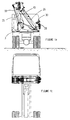
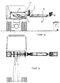
- the truck is indicated generally by reference numeral 1.
- the truck includes an interchangeable collecting container 90, a base bracket 3 which supports an extension arm mechanism (device) generally indicated by reference numeral 4.
- the arm extension mechanism includes two parallel linkages indicated generally by reference numerals 32,42.
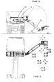
- the first of these parallel linkages 32 is provided by the lift arm 25 and a pivot arm 33 and is defined by pivot points 35,36,37,38.
- the lift arm 25 and pivot arm 33 are connected at pivot points 38,35 respectively to a bracket 50.
- a rotary actuator 6 is mounted on the bracket 50.
- the second of the parallel linkages 42 is provided by the swing/tilt arm 26 and a pivot arm 43 and the parallel linkage 42 is defined by pivot points 45, 46,47,48.
- the pivot points 45,48, about which the swing/tilt arm 26 and the pivot arm 43 move, are provided on a bracket 51 which is also connected to the rotary actuator 6.
- the arm extension mechanism also includes a container engaging member provided at the end of the arm.
- the container engaging member includes a tipping head 29 and a grab unit 30.
- optical encoders are provided at the following locations on the extension arm:
- the arm extension mechanism 4 comprises six hydraulic actuators, namely four ram type actuators and two rotary actuators. These six hydraulic actuators comprise the following:
- the arm extension mechanism 4 can be controlled either manually (manual mode) by the operator who moves one of three joysticks to control the direction and extent of movement of the arm extension mechanism 4. Certain stages of the operational cycle can only be controlled automatically (automatic mode).
- Each of the five actuators is controllable in manual mode, namely the lift hydraulic ram 5, the swing rotary actuator 6, the tilt hydraulic ram 7, turn hydraulic ram 8 and the tip actuator 9 are controlled by their respective joystick, situated in the cab of the truck.
- the corresponding actuator is moved by means of an electrical solenoid valve which opens the hydraulic supply to the actuator, provided that the controls are in manual mode and safety interlocks allow that movement.
- the operator initially manually positions the arm of the truck to grab and lift the garbage container. Once the garbage container has been raised to a position just above the ground, by the arm under manual control, automatic mode can then be selected.
- all six actuators can be moved as necessary to raise the garbage container, and locate it over the collecting container so that it is tipped, emptied and then returned to a position just above the ground.
- Manual control is automatically reinstated once the garbage container has been returned by the arm, to a position just above the ground, so that the operator can manipulate the joysticks to place the garbage container back on the ground and move the arm clear of the garbage container. The operator can then drive the truck to the next collection point if necessary and repeat the operation. Alternatively, if the garbage containers are collected together in a group, the operator will manipulate the joysticks and the arm will be made to grab another garbage container and repeat the tipping and emptying operation.
- the "homing cycle” can be activated by the operator pressing a button on the control panel of the truck.
- the homing cycle will only be used if travelling long distance.
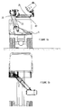
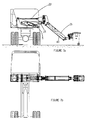
- the "homing cycle” is controlled in automatic mode and brings the arm back from any position in the operational cycle to the home position shown in Figures 9a and 9b ready for transportation.
- the five actuators controllable in manual mode are controlled in the following way.
- the lift ram 5 is moved up or down by moving the first joystick (joystick A) to the left or right.
- a left of centre movement of joystick A corresponds to an up movement of the lift ram 5 and a right of centre movement of the joystick corresponds to a down movement of the lift ram 5.
- the swing rotary actuator 6 is moved forward or backward in relation to the truck by moving the first joystick (joystick A) again but this time forwards or backwards.
- a forward of centre movement of joystick A corresponds to a forward movement of the swing actuator 6 and a backwards of centre movement of the joystick corresponds to a backwards movement of the swing actuator.
- the tilt ram 7 is moved up or down by moving the second joystick (joystick B) left or right.
- a left of centre movement of joystick B corresponds to an up movement of the tilt ram 7 and a right of centre movement of joystick B corresponds to a down movement of the tilt ram 7.
- the turn ram 8 is moved forward or backward in relation to the truck by moving the second joystick (joystick B) again but this time forwards or backwards.
- a forward of centre movement of the joystick corresponds to a forward movement of the turn ram 8 and a backwards of centre movement of the joystick corresponding to a backwards movement of the turn ram 8.
- the tip rotary actuator 9 is moved up or down by moving the third joystick (joystick C) up or down.
- An up of centre movement of the joystick corresponds to an up movement of the tip actuator 9 and a down of centre movement of the joystick corresponds to a down movement of the tip actuator 9.
- This voltage in the range 14 to 20.7 volts is then sent to the electrical solenoid valve controlling the lift ram 5 thereby causing the valve to open and allowing hydraulic oil to pass and fill the cylinder full bore thereby extending the lift ram 5 and moving the lift arm 25 upwardly.
- the absolute encoder 12 relays information regarding the actual position of the lift arm 25 to the programmable logic controller (PLC) discrete input module which is in turn read by the computer program controlling the operational cycle. If the position information regarding the position of the lift arm 25 reaches a pre-determined parameter setting, the PLC will limit the voltage from the analogue output module and thereby prevent certain manual movements.
- PLC programmable logic controller
- This voltage in the range of 14 to 7 volts is then sent to the electrical solenoid valve controlling the lift ram 5, causing the valve to open and thereby allowing hydraulic oil to pass and fill the annular bore of cylinder thereby retracting the hydraulic ram 5 and moving the lift arm 25 downwardly.
- the absolute encoder 12 relays the information regarding the actual position of the lift arm 25 to the discrete input module which is in turn sent by the PLC. If this position information reaches a pre-determined parameter setting, the PLC will limit the voltage from the analogue output module and thereby prevent certain manual movement.
- This voltage in the range of 14 to 7 volts is then sent to the electrical solenoid valve controlling the swing rotary actuator 6, causing the valve to open and thereby allowing oil to pass and fill the B part of the swing rotary actuator 6 and causing the swing/tilt arm 26 to move forwardly.
- the value on absolute encoder 14 which is mounted on the axle of the swing/tilt arm 26 decrements and relays information regarding the actual position of the swing/tilt arm 26 to the discrete input module of the PLC which is in turn read by the PLC. If this position information reaches a pre-determined parameter setting, the PLC will limit the voltage from the analogue output module and thereby prevent certain manual movements.
- This voltage signal is read by the PLC and if all conditions relating to the resulting movement (i.e. swing/tilt arm 26 tilting up) are met, then the analogue output module will send a corresponding voltage signal also in the range 5 to 10 volts to an amplifier which boosts the voltage up to a range from 14 to 20.7 volts dependent on the voltage inputted into the amplifier. This voltage in the range of 14 to 20.7 volts is then sent to the electrical solenoid valve that controls the swing actuator 6, allowing oil to pass into the "A" part of the rotary actuator thereby moving the swing/tilt arm 26 backwards.
- the absolute encoder 14 relays information regarding actual position of the swing/tilt arm 26 to the discrete input module of the PLC, which is in turn read by the PLC. If the position information reaches a pre-determined parameter setting, the program will limit the voltage from the analogue output module and thereby prevent certain manual movement.
- This voltage signal is read by the PLC and if all conditions relating to the resulting movement (i.e. Tilt up) are met, then the analogue output module will send a corresponding voltage signal also in the range 5 to 10 volts to an amplifier which boosts the voltage up to a range from 14 to 20.7 volts dependent on the voltage inputted into the amplifier.
- This 14 to 20.7 volts is then sent to the electrical solenoid valve that controls the tilt ram 7, allowing hydraulic oil to pass and fill the full bore of the cylinder thereby extending the tilt ram 7, and moving the tilt arm 27 up.
- the absolute encoder 16 relays information to the discrete input module of the PLC regarding the actual tilting position of the swing/tilt arm 26.
- This information is read by the PLC and if this position information reaches a pre-determined parameter setting, the PLC controlling the operational cycle will limit the voltage from the analogue output module thereby preventing certain movements in manual mode.
- This voltage of 7 to 14 volts is then sent to the electrical solenoid valve that controls the tilt ram 7 causing the valve to open and allowing hydraulic oil to pass and fill the annular bore of the cylinder of the tilt ram 7 thereby retracting the tilt ram 7 and causing the tilt arm 27 to tilt downwardly.
- the information regarding the actual tilt position of the swing/tilt 26 arm is relayed by the encoder 16 to the discrete input module of the PLC. If this position information reaches a pre-determined parameter setting, the PLC will limit the voltage from the analogue output module and thereby prevent certain movements in manual mode.
- This safety mechanism provides the safety interlocks referred to above.
- a signal is sent to the discrete input module and if all conditions relating to the resulting movement (i.e. turning forward of the grab unit 30) are met, then a signal is sent from the discrete output module to a relay which in turn sends 24 volts to the electrical solenoid valve that controls the "A" port of the turn hydraulic ram 8 thereby causing the valve to open and allowing oil to pass and fill the full bore of the cylinder of the turn hydraulic ram 8 until a signal from the fully forward proximity sensor is sent to the discrete input module resulting in the signal from the discrete output module being terminated.
- the analogue output module When the third joystick (joystick C) is moved up from centre by at least one notch, a signal is sent to the discrete input module and if all conditions relating to the resulting movement i.e. tipping up of the grab unit 30 are met, then the analogue output module will send a signal of between 5 and 10 volts, which will be determined by the PLC to an amplifier which boosts the voltage to a range between 14 to 20.7 volts dependent of the voltage inputted into the amplifier. This voltage of between 14 to 20.7 volts is sent to the electrical solenoid valve that controls the tip actuator 9 and allows hydraulic oil to pass and fill the "A" port of the tip rotary actuator 9 thereby moving the tipping head 29 up.
- the absolute encoder 18 relays the information regarding the actual position of the tipping head 29 to the discrete input module, which is in turn read by the PLC. If this position information reaches a pre-determined parameter setting, the PLC will limit the voltage from the analogue output module and thereby prevent certain movements in manual mode. This provides another safety interlock feature.
- the analogue output module When the third joystick (joystick C) is moved down from centre by at least one notch, a signal is sent to the discrete input module and if all conditions relating to the resulting movement (i.e. tipping down of the grab unit 30) are met, then the analogue output module will send a voltage of pre-determined value between 5 and 0 volts to an amplifier which boost the voltage to a range between 14 and 7 volts dependent on the voltage inputted into the amplifier. This signal of 14 to 7 volts is sent to the electrical solenoid valve that controls the tip actuator 9 thereby causing the valve to open and allowing the hydraulic oil to pass and fill through the "B" port the tip rotary actuator 9 thereby moving the tip head 29 down.
- the absolute encoder 18 mounted on the axle of the Tip head 29 decrements and relays this information regarding the actual position of the tip head 29 to the discrete input module which is in turn read by the PLC. If this position information reaches a pre-determined setting, the PLC will limit the voltage from the analogue output module thereby preventing certain movements in manual mode.
- the automatic garbage container emptying cycle can commence.
- the operator can select automatic mode by pressing a button on the joystick console.
- automatic mode manual control via the joystick is disabled except for the emergency stop mechanism which can be operated by manual control.
- the PLC decides the direction and speed each actuator will move until the garbage container is positioned over the collecting container hopper. The speed and direction of each movement is dependent on the position of the lift arm 25, the swing/tilt arm 26 and the tipping head 29 at the on-set of automatic mode.
- the PLC When the garbage container is emptied, the PLC returns each arm and tipping head 29 to the start position at the same speed and ceases automatic movement, at the same time returning manual control to the operator.
- the operator When the sequence is complete, the operator is informed by a light on the joystick console and once again manual operation is reinstated.
- the primary function of the hydraulic circuit used in the garbage collection truck is to convert the truck's power to a controllable mechanical action, which in turn is used to control the actions of the lift arm.
- the truck has been fitted with a load sensing hydraulic system.
- the load sensing system differs from conventional systems in that it will only deliver the flow of oil that is required.
- the system has a special feed back line from the main block to the load sensing pump. This feedback line informs the pump of the consumption of oil and hence how much oil the pump is to deliver.
- the valves used to control the movements of the lift, swing, tilt and tip actions can deliver a flow of oil that is proportional to the amount by which the joystick is moved off centre. This gives the operator full control over the speed of the lift arm 25, and swing/tilt arm 26 and grab unit 30 and hence the positional accuracy.
- the programmable logic controller also takes advantage of the proportional operation of the lift, swing, tilt and tip valves as the range of speeds permits the use of uniform acceleration and deceleration thereby increasing the respective arms 1 fluidity of movement during homing and automatic cycles.
- the turn and clamp cylinders are non proportional, as these actions only require one slow speed i.e. the valves used to control the turn and clamp actions do not deliver a flow of oil that is proportional to the amount by which the joystick is moved off centre.
- the hydraulic circuit comprises the following elements:
- Valve 108 which is a solenoid operated, four port, two position valve. The pressure and tank lines join in the neutral position, this means that the valve 108 operates as a master valve, controlling the supply of oil to the main block.
- Valves numbered 109,110,111 and 112 are all solenoid operated, proportional valves. The fact that these valves 109,110,111 and 112 are proportional permits the valves to control the flow rate of oil anywhere between maximum and zero to each actuator.
- Valve numbered 113 and 114 are non proportional valves, that is to say that these valves do not possess the capability to vary the flow rate into the cylinders. Therefore, valves 113,114 can only operate at one flow rate, hence given the actuators which they control, namely, the turn hydraulic ram 8 and clamp ram 10, there is only one fixed operating speed possible for these rams 8,10.
- Components numbered 115,116,117,118,119 and 120 are all internal cross line relief valves. These valves 115,116,117,118 and 119 can be set to limit the working force of each actuator. In the case of the present invention these valves 115,116,117,118 and 119 have been set to limit the lifting force to that required to lift 250Kg and also to limit the down force to the minimum required to place the garbage container back on the pavement, as a result the forces applied in an accidental collision can be limited.
- Valves numbered 121,122,123,124 and 125 are all dual over-centre valves. These valves 121,122,123,124 and 125 require a signal pressure from the pressure line before they will open for operation.
- the valves 121,122,123,124 and 125 are used to prevent the arm drifting in the transport position. They are also used to prevent the arm from falling from an elevated portion, in the event of a major oil leak.
- the valves 121,122,123,124 and 125 prevent the rate of movement of any particular component from being faster than the rate of flow of oil to the pump, thereby increasing the fluidity of movement of the arm.
- Valve number 126 is a pilot operated check valve. This valve 126 compares the pressure trying to open the cylinder with a pre-applied spring pressure. The valve is used in the device of the present invention to prevent the lifted garbage container from opening the clamp during a tipping operation.
- the hydraulic line 133 in Figure 15 is the load sensing line, this line provides feed back to the load sensing pump to inform the pump of the consumption of oil, the pump then responds by delivering more or less oil depending on the signal given.
- the interchangeable collection container 90 provided on the truck 1 as shown in Figure 16 may be of the type described in European Patent Specification No. EP 0 638 491 and includes a receiving member (not shown) coupled to a compacting member (not shown) for compacting garbage deposited in the receiving member into the container.
- the collection container may be of another type, for example, an open top container.
- the advantage of the truck and device of the present invention is that the device is easily manoeuvred to a high degree of accuracy so that the device can reach for garbage containers which have been collected together in a group and are arranged in a random fashion, without having to move the truck.
- the device can be manipulated so that successive garbage containers at a collection point can be grabbed, lifted, tipped and returned to the ground, the movements of the arm are not jerky but are smooth during both manual and automatic operation.
Landscapes
- Engineering & Computer Science (AREA)
- Mechanical Engineering (AREA)
- Refuse-Collection Vehicles (AREA)
Priority Applications (1)
| Application Number | Priority Date | Filing Date | Title |
|---|---|---|---|
| EP97650030A EP0894739A1 (de) | 1997-07-31 | 1997-07-31 | Vorrichtung zur Handhabung von Müllbehältern |
Applications Claiming Priority (1)
| Application Number | Priority Date | Filing Date | Title |
|---|---|---|---|
| EP97650030A EP0894739A1 (de) | 1997-07-31 | 1997-07-31 | Vorrichtung zur Handhabung von Müllbehältern |
Publications (1)
| Publication Number | Publication Date |
|---|---|
| EP0894739A1 true EP0894739A1 (de) | 1999-02-03 |
Family
ID=8230117
Family Applications (1)
| Application Number | Title | Priority Date | Filing Date |
|---|---|---|---|
| EP97650030A Withdrawn EP0894739A1 (de) | 1997-07-31 | 1997-07-31 | Vorrichtung zur Handhabung von Müllbehältern |
Country Status (1)
| Country | Link |
|---|---|
| EP (1) | EP0894739A1 (de) |
Cited By (13)
| Publication number | Priority date | Publication date | Assignee | Title |
|---|---|---|---|---|
| WO2004052756A1 (en) * | 2002-12-09 | 2004-06-24 | Oshkosh Truck Corporation | Refuse vehicle control system and method |
| WO2005030614A1 (en) * | 2003-09-22 | 2005-04-07 | Oshkosh Truck Corporation | Refuse vehicle control system and method |
| US7711460B2 (en) | 2001-01-31 | 2010-05-04 | Oshkosh Corporation | Control system and method for electric vehicle |
| US7729831B2 (en) | 1999-07-30 | 2010-06-01 | Oshkosh Corporation | Concrete placement vehicle control system and method |
| US7848857B2 (en) | 2001-01-31 | 2010-12-07 | Oshkosh Corporation | System and method for braking in an electric vehicle |
| ES2361363A1 (es) * | 2011-02-04 | 2011-06-16 | Ricardo Romero Marti (40%) | Sistema inteligente para el control y gestión de un vehículo motorizado para la recogida de contenedores de residuos. |
| US8139109B2 (en) | 2006-06-19 | 2012-03-20 | Oshkosh Corporation | Vision system for an autonomous vehicle |
| CN104118678A (zh) * | 2014-06-03 | 2014-10-29 | 广西合浦县惠来宝机械制造有限公司 | 垃圾装载机构 |
| US8947531B2 (en) | 2006-06-19 | 2015-02-03 | Oshkosh Corporation | Vehicle diagnostics based on information communicated between vehicles |
| US9145905B2 (en) | 2013-03-15 | 2015-09-29 | Oshkosh Corporation | Independent load sensing for a vehicle hydraulic system |
| US9845191B2 (en) | 2013-08-02 | 2017-12-19 | Oshkosh Corporation | Ejector track for refuse vehicle |
| WO2020114020A1 (zh) * | 2018-12-07 | 2020-06-11 | 长沙中联重科环境产业有限公司 | 机械臂、垃圾车和垃圾车的上料方法 |
| CN115676191A (zh) * | 2022-12-24 | 2023-02-03 | 聊城市誉林工业设计有限公司 | 一种侧装式垃圾收运车 |
Citations (5)
| Publication number | Priority date | Publication date | Assignee | Title |
|---|---|---|---|---|
| US5018929A (en) * | 1989-12-26 | 1991-05-28 | Carson William S | Truck body and apparatus for automated collection of recyclable materials |
| WO1992001612A1 (en) * | 1990-07-24 | 1992-02-06 | Stephen Wayne Holtom | Refuse loader arm |
| AU640156B2 (en) * | 1989-08-08 | 1993-08-19 | Macdonald Johnston Engineering Company Pty Limited | Side lift rubbish bin lifter |
| WO1994021541A1 (en) * | 1993-03-24 | 1994-09-29 | The Heil Company | Top mounted container handling apparatus |
| EP0638491A1 (de) * | 1993-08-09 | 1995-02-15 | Van Dooremaal Holding | Fahrzeug mit Sammelbehälter und Vorrichtung zum Heben und Entleeren von Müllbehältern in diesen Sammelbehälter |
-
1997
- 1997-07-31 EP EP97650030A patent/EP0894739A1/de not_active Withdrawn
Patent Citations (6)
| Publication number | Priority date | Publication date | Assignee | Title |
|---|---|---|---|---|
| AU640156B2 (en) * | 1989-08-08 | 1993-08-19 | Macdonald Johnston Engineering Company Pty Limited | Side lift rubbish bin lifter |
| US5018929A (en) * | 1989-12-26 | 1991-05-28 | Carson William S | Truck body and apparatus for automated collection of recyclable materials |
| WO1992001612A1 (en) * | 1990-07-24 | 1992-02-06 | Stephen Wayne Holtom | Refuse loader arm |
| WO1994021541A1 (en) * | 1993-03-24 | 1994-09-29 | The Heil Company | Top mounted container handling apparatus |
| EP0638491A1 (de) * | 1993-08-09 | 1995-02-15 | Van Dooremaal Holding | Fahrzeug mit Sammelbehälter und Vorrichtung zum Heben und Entleeren von Müllbehältern in diesen Sammelbehälter |
| EP0638491B1 (de) | 1993-08-09 | 1997-03-12 | Van Dooremaal Holding | Fahrzeug mit Sammelbehälter und Vorrichtung zum Heben und Entleeren von Müllbehältern in diesen Sammelbehälter |
Cited By (18)
| Publication number | Priority date | Publication date | Assignee | Title |
|---|---|---|---|---|
| US7729831B2 (en) | 1999-07-30 | 2010-06-01 | Oshkosh Corporation | Concrete placement vehicle control system and method |
| US7835838B2 (en) | 1999-07-30 | 2010-11-16 | Oshkosh Corporation | Concrete placement vehicle control system and method |
| US7072745B2 (en) | 1999-07-30 | 2006-07-04 | Oshkosh Truck Corporation | Refuse vehicle control system and method |
| US7848857B2 (en) | 2001-01-31 | 2010-12-07 | Oshkosh Corporation | System and method for braking in an electric vehicle |
| US7711460B2 (en) | 2001-01-31 | 2010-05-04 | Oshkosh Corporation | Control system and method for electric vehicle |
| US7412307B2 (en) | 2002-08-02 | 2008-08-12 | Oshkosh Truck Corporation | Refuse vehicle control system and method |
| US7725225B2 (en) | 2002-12-09 | 2010-05-25 | Oshkosh Corporation | Refuse vehicle control system and method with footboard |
| WO2004052756A1 (en) * | 2002-12-09 | 2004-06-24 | Oshkosh Truck Corporation | Refuse vehicle control system and method |
| WO2005030614A1 (en) * | 2003-09-22 | 2005-04-07 | Oshkosh Truck Corporation | Refuse vehicle control system and method |
| US8139109B2 (en) | 2006-06-19 | 2012-03-20 | Oshkosh Corporation | Vision system for an autonomous vehicle |
| US8947531B2 (en) | 2006-06-19 | 2015-02-03 | Oshkosh Corporation | Vehicle diagnostics based on information communicated between vehicles |
| US9420203B2 (en) | 2006-06-19 | 2016-08-16 | Oshkosh Defense, Llc | Vision system for a vehicle |
| ES2361363A1 (es) * | 2011-02-04 | 2011-06-16 | Ricardo Romero Marti (40%) | Sistema inteligente para el control y gestión de un vehículo motorizado para la recogida de contenedores de residuos. |
| US9145905B2 (en) | 2013-03-15 | 2015-09-29 | Oshkosh Corporation | Independent load sensing for a vehicle hydraulic system |
| US9845191B2 (en) | 2013-08-02 | 2017-12-19 | Oshkosh Corporation | Ejector track for refuse vehicle |
| CN104118678A (zh) * | 2014-06-03 | 2014-10-29 | 广西合浦县惠来宝机械制造有限公司 | 垃圾装载机构 |
| WO2020114020A1 (zh) * | 2018-12-07 | 2020-06-11 | 长沙中联重科环境产业有限公司 | 机械臂、垃圾车和垃圾车的上料方法 |
| CN115676191A (zh) * | 2022-12-24 | 2023-02-03 | 聊城市誉林工业设计有限公司 | 一种侧装式垃圾收运车 |
Similar Documents
| Publication | Publication Date | Title |
|---|---|---|
| AU690831B2 (en) | A side loader for curbside refuse containers | |
| US6332745B1 (en) | Compacting system and refuse vehicle | |
| US3765554A (en) | Self-loading truck | |
| AU694836B2 (en) | Automated refuse vehicle | |
| US5890865A (en) | Automated low profile refuse vehicle | |
| EP0117939B1 (de) | Müllfahrzeug | |
| US5011363A (en) | Extend and retract control for fork lifts | |
| US11512447B2 (en) | Systems and methods to improve work machine stability based on operating values | |
| US10214875B2 (en) | Working machine having a hydraulically operated implement | |
| US4465425A (en) | Device for the paraxial kinetic control of a lifting machine boom | |
| US20060263189A1 (en) | System and a method for moving an implement of a vehicle | |
| EP0512469A1 (de) | Sammelfahrzeug und Verfahren zum Entleeren von Behältern | |
| JP2784593B2 (ja) | 持上げ運搬作業機 | |
| JPH089234Y2 (ja) | 持上げ運搬作業機 | |
| GB2222813A (en) | Refuse collection vehicle | |
| GB2279321A (en) | Collection vechicle | |
| JP2784592B2 (ja) | 持上げ運搬作業機 | |
| JPH1054055A (ja) | 作業機の昇降制御装置 | |
| JPH06135698A (ja) | フォークリフトの荷役制御装置 | |
| RU2131838C1 (ru) | Предохранительное устройство для подъемно-опрокидывающих устройств в режиме движения | |
| JP3930642B2 (ja) | フロントローダ | |
| CA1147241A (en) | Hydraulic system for material compacting apparatus | |
| US20060180382A1 (en) | Telescopic loader, in particular a reach stacker | |
| JP2024041936A (ja) | 塵芥収集車 | |
| NL2007837C2 (nl) | Hefmechanisme, beladingssysteem en vuilnisauto voorzien daarvan, en werkwijze daarvoor. |
Legal Events
| Date | Code | Title | Description |
|---|---|---|---|
| PUAI | Public reference made under article 153(3) epc to a published international application that has entered the european phase |
Free format text: ORIGINAL CODE: 0009012 |
|
| AK | Designated contracting states |
Kind code of ref document: A1 Designated state(s): BE DE GB IE NL |
|
| 17P | Request for examination filed |
Effective date: 19990730 |
|
| AKX | Designation fees paid |
Free format text: BE DE GB IE NL |
|
| 17Q | First examination report despatched |
Effective date: 20000316 |
|
| GRAG | Despatch of communication of intention to grant |
Free format text: ORIGINAL CODE: EPIDOS AGRA |
|
| GRAG | Despatch of communication of intention to grant |
Free format text: ORIGINAL CODE: EPIDOS AGRA |
|
| GRAH | Despatch of communication of intention to grant a patent |
Free format text: ORIGINAL CODE: EPIDOS IGRA |
|
| STAA | Information on the status of an ep patent application or granted ep patent |
Free format text: STATUS: THE APPLICATION IS DEEMED TO BE WITHDRAWN |
|
| 18D | Application deemed to be withdrawn |
Effective date: 20020216 |