EP0894884A2 - Rouleau d'entraínement pour un dispositif d'alimentation en fil - Google Patents
Rouleau d'entraínement pour un dispositif d'alimentation en fil Download PDFInfo
- Publication number
- EP0894884A2 EP0894884A2 EP98113069A EP98113069A EP0894884A2 EP 0894884 A2 EP0894884 A2 EP 0894884A2 EP 98113069 A EP98113069 A EP 98113069A EP 98113069 A EP98113069 A EP 98113069A EP 0894884 A2 EP0894884 A2 EP 0894884A2
- Authority
- EP
- European Patent Office
- Prior art keywords
- gear
- drive roller
- roller according
- wheel
- drive
- Prior art date
- Legal status (The legal status is an assumption and is not a legal conclusion. Google has not performed a legal analysis and makes no representation as to the accuracy of the status listed.)
- Withdrawn
Links
- 230000005540 biological transmission Effects 0.000 claims description 32
- 238000009940 knitting Methods 0.000 claims description 16
- 230000001186 cumulative effect Effects 0.000 abstract 1
- 239000000969 carrier Substances 0.000 description 2
- 230000001276 controlling effect Effects 0.000 description 2
- 230000008878 coupling Effects 0.000 description 2
- 238000010168 coupling process Methods 0.000 description 2
- 238000005859 coupling reaction Methods 0.000 description 2
- 230000004323 axial length Effects 0.000 description 1
- 238000010276 construction Methods 0.000 description 1
- 210000003746 feather Anatomy 0.000 description 1
- 238000004519 manufacturing process Methods 0.000 description 1
- 230000002093 peripheral effect Effects 0.000 description 1
- 230000001105 regulatory effect Effects 0.000 description 1
Images

Classifications
-
- D—TEXTILES; PAPER
- D04—BRAIDING; LACE-MAKING; KNITTING; TRIMMINGS; NON-WOVEN FABRICS
- D04B—KNITTING
- D04B15/00—Details of, or auxiliary devices incorporated in, weft knitting machines, restricted to machines of this kind
- D04B15/38—Devices for supplying, feeding, or guiding threads to needles
- D04B15/48—Thread-feeding devices
-
- B—PERFORMING OPERATIONS; TRANSPORTING
- B65—CONVEYING; PACKING; STORING; HANDLING THIN OR FILAMENTARY MATERIAL
- B65H—HANDLING THIN OR FILAMENTARY MATERIAL, e.g. SHEETS, WEBS, CABLES
- B65H2403/00—Power transmission; Driving means
- B65H2403/20—Belt drives
- B65H2403/25—Arrangement for tensioning
-
- B—PERFORMING OPERATIONS; TRANSPORTING
- B65—CONVEYING; PACKING; STORING; HANDLING THIN OR FILAMENTARY MATERIAL
- B65H—HANDLING THIN OR FILAMENTARY MATERIAL, e.g. SHEETS, WEBS, CABLES
- B65H2403/00—Power transmission; Driving means
- B65H2403/40—Toothed gearings
- B65H2403/42—Spur gearing
-
- B—PERFORMING OPERATIONS; TRANSPORTING
- B65—CONVEYING; PACKING; STORING; HANDLING THIN OR FILAMENTARY MATERIAL
- B65H—HANDLING THIN OR FILAMENTARY MATERIAL, e.g. SHEETS, WEBS, CABLES
- B65H2403/00—Power transmission; Driving means
- B65H2403/40—Toothed gearings
- B65H2403/43—Bevel gearing
-
- B—PERFORMING OPERATIONS; TRANSPORTING
- B65—CONVEYING; PACKING; STORING; HANDLING THIN OR FILAMENTARY MATERIAL
- B65H—HANDLING THIN OR FILAMENTARY MATERIAL, e.g. SHEETS, WEBS, CABLES
- B65H51/00—Forwarding filamentary material
- B65H51/02—Rotary devices, e.g. with helical forwarding surfaces
- B65H51/04—Rollers, pulleys, capstans, or intermeshing rotary elements
- B65H51/06—Rollers, pulleys, capstans, or intermeshing rotary elements arranged to operate singly
-
- B—PERFORMING OPERATIONS; TRANSPORTING
- B65—CONVEYING; PACKING; STORING; HANDLING THIN OR FILAMENTARY MATERIAL
- B65H—HANDLING THIN OR FILAMENTARY MATERIAL, e.g. SHEETS, WEBS, CABLES
- B65H51/00—Forwarding filamentary material
- B65H51/32—Supporting or driving arrangements for forwarding devices
Definitions
- the invention relates to a drive roller as defined in the preamble of claim 1 Type for a thread delivery device, in particular on knitting machines.
- a drive roller of this type is used in particular on circular knitting machines and in connection used with so-called band suppliers. It serves to drive one endless drive belt with a pre-selected wrap angle on the circumference the drive roller and a plurality of thread delivery rollers and for non-slip, positive delivery of threads, e.g. between the drive belt and associated Delivery rollers are guided (DE-PS 1 143 294). Alternatively, it would be possible to use the Drive belt separate additional rollers or others attached to the delivery rollers To drive thread delivery devices as the band feeders described.
- a Changing the thread delivery speed can be done by changing the diameter the drive roller can be brought about, which, however, usually only when the Drive roller and thus only possible when the circular knitting machine is at a standstill (DE-PS 24 11 876, DE-PS 1 286 680, DE-PS 28 46 279).
- a drive roller of the type described above becomes, whose adjusting device also a relative rotation of the two disks with continuous rotation of the drive roller, i.e. with the circular knitting machine running enables.
- Such drive rollers still have some shortcomings.
- a known drive roller of this type (DE-OS 20 30 333 contains the adjusting device for example a stepper motor coupled to the drive roller and rotating with it, the one of the two discs can rotate relative to the other disc and so is connected to a program control via slip rings.
- Such an arrangement is structurally complex and not always desirable, since it is the manual adjustment of the Thread speeds when setting up a knitting machine or the like are impeded or difficult and is prone to failure and expensive because of the required slip rings.
- the invention is therefore based on the object, the drive roller of the aforementioned Form genus so that no revolving motor is needed, the actual diameter change nevertheless either automatically or manually can take place and with great ease of movement of the different parts a large adjustment range can be produced.
- a particular advantage of the invention is that the invention provided sum or differential gear an arbitrarily large adjustment path and thus allows small angles for the spiral grooves, the guide grooves for the Adjustment of the two discs to each other can be completely omitted, so that a high Ease of adjustment is achieved.
- the adjustment element needs not circulate with it, so that it can be done manually or by means of a simple Program control can be adjusted.
- the invention Drive roller easily on existing thread delivery devices as a replacement for others Drive rollers are attached.
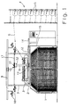
- the circular knitting machine according to FIG. 1 has a frame 1 with a base plate 2 and one rotatable on this mounted needle cylinder 3.
- a thread delivery device On the frame 1 is by means of carriers 7 and / or a support ring 8 carried by them supported a thread delivery device.
- This contains a fixed on the base plate 2, tubular support section 9, in which a shaft 10 is rotatably mounted, the protrudes from the tubular support section 9 at both ends.
- a gear 11 On the in Fig. 1st lower end of the shaft 10, a gear 11 is fixed, which is driven by a gear 12 is connected to a gear 14 which sits on a drive shaft 15 which in is not shown in the circular knitting machine and with a preselected gear ratio and is driven synchronously with the needle cylinder 3.
- the thread delivery device also includes one at the other end of the shaft 10 attached drive roller 16 (Fig.
- an endless drive belt 17 is present, which at least partially abuts the periphery of a plurality of driven delivery rollers 18 which are rotatable are mounted on the carriers 7 or in the support ring 8.
- These delivery rollers 18 are not assigned thread eyelets, which e.g. serve in a known manner to guide the threads 6 so that they each loop around the delivery rollers 18 several times or between the circumference of an assigned delivery roller 18 and the drive belt 17 come to rest and are therefore positively or forcibly guided in the direction of the arrow become.
- Thread delivery devices of this type and their function are generally known (DE-PS 1 143 294, DE 39 31 997 A1 or EP 0 285 828 A1) and therefore do not need are explained in more detail.
- the drive belt 17 running over the drive roller 16 can be by means of a preferably automatic tensioning device, e.g. one agile stored tensioning roller 19, under the influence of a force, in particular under the Influence of a tension spring 20 acting on it or a weight acting on it stands, are kept taut so that when the diameter of the drive roller changes 16 the drive belt 17 is automatically compensated.
- a preferably automatic tensioning device e.g. one agile stored tensioning roller 19
- a force in particular under the Influence of a tension spring 20 acting on it or a weight acting on it stands
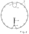
- the effective diameter of the one wrapped by the drive belt 17 3 has a first, preferably plane-parallel, section of the drive roller 16 Disc 21 which e.g. by means of a feather key or the like. non-rotatably with the shaft 10 connected is.
- the disc 21 is a second with the first disc 21 coaxial, preferably also plane-parallel disc 22 arranged, which is rotatable with respect to the first disc 21.
- the first disc 21 has on it lower, the second disk 22 facing surface extending radially to the shaft 10 Grooves 23, whereas the second disc 22 on its associated with the first disc 21 Top is provided with at least one spiral groove 24.
- the circumference or form the peripheral surface of the drive roller 16 and for contacting the drive belt 17 serve.
- the effective diameter of the circumference of the drive roller 16 can be changed in that with pins 26 and 27, projections or the like in the grooves 23, 24 mounted sliders 25 by relative rotation of the two Disks 21 and 22 are displaced radially outwards or inwards to one another.
- Drive rollers 16 of this type which are often referred to as regulating discs, and their function are also generally known (DE-PS'en 1 286 680 and 28 46 279) and therefore do not need to be explained in more detail. To avoid repetitions are therefore the two last-mentioned documents and DE-PS 1 143 294, DE 39 31 997 A1 and EP 0 285 828 A1 on the subject of the present disclosure made.
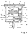
- FIG. 3 A first embodiment of the adjusting device 31 according to the invention for the Drive roller 16 is shown in FIG. 3. It contains a stationary, pot-shaped housing 32, which preferably has a cylindrical cross section, is open at one end and at the opposite end merges into a sleeve-like approach which corresponds to that from FIG. 1 Obvious, tubular support portion 9 in which the shaft 10 is rotatably supported is.
- the second disc 22 On the front edge surrounding the open end of the housing 32 is the second disc 22 rotatably supported in the manner of a cover and for this purpose e.g. with a cylindrical recess 33 receiving the edge, while the first Disk 21 on the side of the disk 22 facing away from the housing 32 and coaxial to it is arranged.
- the two disks 21 and 22 each have a central central opening, that of one End of the shaft 10 is penetrated. This end of the shaft 10 is free on the one hand rotatably supported in the second disc 22.
- the first disc 21 is axial fixedly and non-rotatably mounted on the end of the shaft 10, e.g. one on her attached hub 34 by means of a fastening screw 35 or the like. On the shaft is attached.
- the adjusting device 31 is shown in FIG. 3 as a spur gear, in Housing 32 housed sum or differential gear formed. This is on the shaft 10 and in the vicinity of the support section 9 a first effective as a drive part Gear 36 arranged, the rotationally fixed by means of a schematically shown wedge 37 the shaft 10 is connected. Furthermore, is near the open end of the housing 32 second gear 38 acting as the driven part is loosely rotatably mounted on the shaft 10. This gear 38 is provided with a collar 39 facing the second disk 22, the one on the second disk 22 protruding into the housing 32 Collar 40 sits and axially by means of a fastening screw 41 is immovably attached to the collar 40.
- the first gear 36 is in engagement with a third gear 42 on its circumference, which is rotatably mounted on a bearing pin 43 arranged parallel to the axis 10.
- the bearing pin 43 is in turn eccentrically attached to a component 44 which on a between the support section 9 and the first gear 36 located in such a way rotatable is mounted on the shaft 10 that the third gear 42 according to the old of a planet gear Carry out a circular movement around the first gear 36 and thereby on its circumference can roll off.
- the component 44 preferably contains a rotatable one on the Shaft 10 mounted sleeve 45 and a radially projecting therefrom, the bearing pin 43 supporting arm 46.
- the component 44 is provided with a e.g. between him and the fourth gear 47 arranged in the support section 9, which e.g. on the Sleeve 45 arranged and fastened to it by means of a fastening screw 48.
- the component 44 and the fourth gear 47 could also be formed in one piece or be firmly connected to one another in part.
- the gear 47 stands with one Adjusting element 49 in the form of another gear engaged in parallel to the shaft 10 arranged bearing pin 50 is attached.
- This is either rotatable in the Housing 32 mounted and with a handwheel arranged outside the housing 32 3 or, as FIG. 3 shows, as an output shaft in or on the housing 32 attached electric motor 51, which is preferably designed as a reversing motor and can optionally be operated in opposite directions of rotation.
- the first gear wheel 36 is furthermore mounted on a shaft which is loosely rotatable on the shaft 10 Transmission gear 52 with the second gear 38 in operative connection.
- the transmission gear 52 consists of a between the gears 36 and 38 on the Shaft 10 rotatably mounted sleeve, at the ends of which a separate gear 52a or 52b is formed, of which one with the third gear 42 and the other with the intermediate gear 53 meshes, the one parallel to the shaft 10, the distance of the Gears 52a, 52b has a corresponding distance from the third gear 42.
- the gears 42, 53 each have such a thickness in the axial direction that they simultaneously with the gearwheels 36, 52a and 52b, 38, which are spaced apart in the axial direction can be engaged.
- Other constructions are also alternative possible because e.g.
- the transmission gear 52 also from one over the entire axial length continuous gear and each of the gears 42, 53 from two axially spaced, but firmly connected gears could be made. Accordingly, it would also be possible to manufacture the gear wheels 52a, 52b separately and then non-rotatably connected.
- the gears 36, 38, 42, 47, 49, 52 and 53 all consist of spur gears.
- the first and the second gear 36 and 38 have the same diameter and Number of teeth and thus the same modules.
- the transmission gear 52 or the two Gears 52a, 52b preferably have the same diameter as the gears 36 and 38, but a slightly different number of teeth.
- the third gear 42 and that Intermediate gear 53 are among one another with regard to the diameter and the number of teeth preferably identical, with their module preferably that of the gears 36, 38 or also corresponds to that of the gear wheels 52a, 52b.
- the gears 36, 38, 47 and 52 (or 52a, b) are preferably all arranged coaxially.
- the number of teeth of the Gears 47, 49 are arbitrary in themselves, but their module should be the same.
- the shaft 10 and therefore also the first disc 21 driven at a speed derived from the drive shaft 15 (FIG. 1), during the drive of the disc 22, which is loosely seated on the shaft 10, via the summation gear he follows. If both discs 21, 22 rotate at the same speed, the setting remains of the diameter of the drive roller 16 unchanged. The disc 22 becomes relative turned to the disc 21, this diameter is changed.
- the gears 36 and 38 have, for example 50 teeth each, while the transmission gear 52 or its gears 52a, b each have 51 teeth. This slight difference is despite the same Diameter of the gear wheels 36, 38 and 52 and their engagement with the gear wheels 42 and 53 not problematic and easily due to a profile shift realizable. Therefore, the gear 36 of the shaft 10 at a speed in rotation offset, which corresponds to the speed of the first disc 21, then that Gear 52a in a fixed position or fixing the bearing pin 43 per revolution the shaft 10 rotated by an amount slower than the gear 36, which corresponds to a tooth. The direction of rotation of both gears 36, 52a is identical.
- the additional rotational movement thus exerted on the transmission gear 52 acts via the intermediate gear 53 on the gear 38 and thus on the second disc 22 from. Therefore, it is possible to turn a by rotating the adjusting member 49 relative rotation of the two disks 21, 22 and thus a change in the diameter bring about the drive roller 16, it being immaterial whether the shaft 10 is in Rotation or at a standstill.
- the extent of the change in diameter depends on the different number of teeth of the gears 36, 52 and 38 on the size of the Angle of rotation of the arm 46. If the arm 46 or the adjusting element 49 after a If the intended change in diameter is brought to a standstill, the diameter remains the drive roller 16 constant from this moment on.
- n 38 [(n 36 -n 46 ) Z 36 / z 52a + n 46 ] z 52b / z 36
- n x is the rotational speed of the various gearwheels with the reference symbols x and z x the associated number of teeth
- n 46 is the rotational speed at which the arm 46 and the bearing journal 43 rotate with the gearwheel 42 around the shaft 10.
- n 38 299.80 rpm, from which, for example, the required duration can be calculated for which the electric motor 51 must be switched on in order to bring about a preselected change in diameter of the drive roller 16.
- the gearwheel 47 is preferably designed as a worm wheel and the adjusting element 49 as a worm, so that self-locking occurs.
- Bearings e.g. in the form of roller bearings. This is in Fig. 3 for those gears that are driven at higher speeds by needle bearings 55 indicated. It is also indicated in Fig. 3 that the gears 47, 36 and 52nd for example, thereby held essentially axially immovable on the shaft 10 are that they between the gear 38 attached to the shaft 10 and one also can be arranged on the shaft 10 attached sleeve 56.
- a transmission gear 58 includes two coaxial gears 58a and 58b which are conical trained and open to opposite sides.
- the gear 58a stands a correspondingly conical first gear 59 and gear 58b correspondingly conical second gear 60 opposite.
- the two Gears 59 and 60 correspond to gears 36 and 38 in Fig. 3 and are therefore analog with the shaft 10 or the second disk 22 firmly connected, while Transmission gear 58 is loosely rotatable on the shaft 10.
- the first gear 59 and transmission gear 58 or its gear 58a on the circumference via a third conical gear 61 and the second gear 60 and the transmission gear 58 or its gear 58b via a conical intermediate gear 62 in operative connection.
- the third gear 61 is eccentric to the one hand Shaft 10 and by means of a bearing pin 63 mounted on an arm 64 which is radial from protrudes a component 65, which by means of a corresponding to the gear 47 in Fig. 3, with him integrally manufactured gear 66 rotatably mounted on the shaft 10 and with the Adjustment element 49 is engaged.
- the intermediate gear 62 is by means of a attached to the housing 32 pivot pin 67 rotatably but fixedly mounted thereon.
- a difference to the embodiment of FIG. 3 is mainly that the Journal 63, 67 substantially perpendicular to the shaft 10 instead of parallel to it are arranged.
- the transmission gear 58 in the opposite direction of rotation the first gear 59 is driven and therefore the intermediate gear 62 serves to the second gear 60 opposite to the transmission gear 58 and thus in to drive the same direction of rotation as the first gear 59.
- gear 66 stationary Therefore, the gears 59, 60 and thus the two disks 21, 22 always rotate same speed, provided the coaxially arranged gears 58a, 58b, 59 and 60 have the same diameter, number of teeth and modules.
- the gears 61, 62 have preferably the same number of teeth and diameter among themselves.
- a corresponding change in diameter can also in this embodiment running circular knitting machine can be effected.
- that of the Orbital movement of the gear 61 induced speed of the rotation of the first gear 59 determined speed of the transmission gear 58, as long as the Electric motor 51 is turned on. Otherwise, the mode of operation of the embodiment 4 analogous to that of FIG. 3rd
- n 60 n 59 - 2 ⁇ n 64 , where n 59 and n 60 are the speeds of the gears 59 and 60, while n 64 is the speed at which the arm 64 and the third gear 61 rotates.
- 3 and 4 can be particularly advantageous as part of a Program control or a control device can be used.
- the adjusting element 49 e.g. connected to a tax body, of this depending on one with the circular knitting machine or the like realizing knitting pattern adjusted and between the individual adjustment movements locked.
- the electric motor 51 could itself be part of the program control device and by signals from a pattern device controlling the circular knitting machine can be switched on or off.
- the Electric motor 51 or the adjusting element 49 on the other hand, as an actuator of the thread tension, the thread speed or the like. to automatically keep the monitored values constant by the actual values of these
- the quantities are continuously monitored and compared with setpoints specified in the model and by using the difference between the actual and target values, the electric motor 51 controlling signal is derived.
- the invention is not restricted to the exemplary embodiments described, which are based on could be modified in many ways. This applies, for example, to the arrangement of the grooves 23, 24 in the disks 21 and 22, which could also be interchanged.
- Continue 3 and 4 are only to be understood as examples.
- Especially the specified number of teeth can be changed, e.g. the number of teeth of the gears 36, 38 could also be larger than the number of teeth of the transmission gear 52.
Landscapes
- Engineering & Computer Science (AREA)
- Textile Engineering (AREA)
- Knitting Machines (AREA)
- Looms (AREA)
Applications Claiming Priority (2)
| Application Number | Priority Date | Filing Date | Title |
|---|---|---|---|
| DE19733266 | 1997-08-01 | ||
| DE19733266A DE19733266A1 (de) | 1997-08-01 | 1997-08-01 | Antriebsrolle für eine Fadenliefervorrichtung |
Publications (2)
| Publication Number | Publication Date |
|---|---|
| EP0894884A2 true EP0894884A2 (fr) | 1999-02-03 |
| EP0894884A3 EP0894884A3 (fr) | 1999-12-22 |
Family
ID=7837667
Family Applications (1)
| Application Number | Title | Priority Date | Filing Date |
|---|---|---|---|
| EP98113069A Withdrawn EP0894884A3 (fr) | 1997-08-01 | 1998-07-14 | Rouleau d'entraínement pour un dispositif d'alimentation en fil |
Country Status (7)
| Country | Link |
|---|---|
| EP (1) | EP0894884A3 (fr) |
| JP (1) | JPH11117152A (fr) |
| KR (1) | KR19990023241A (fr) |
| CN (1) | CN1207360A (fr) |
| DE (1) | DE19733266A1 (fr) |
| SG (1) | SG81934A1 (fr) |
| TW (1) | TW498120B (fr) |
Cited By (1)
| Publication number | Priority date | Publication date | Assignee | Title |
|---|---|---|---|---|
| US6745597B2 (en) * | 2001-12-31 | 2004-06-08 | China Textile Institute | Positive feeding method and apparatus of an encoder |
Families Citing this family (3)
| Publication number | Priority date | Publication date | Assignee | Title |
|---|---|---|---|---|
| DE19923802B4 (de) | 1999-05-19 | 2012-09-13 | Sipra Patententwicklungs- Und Beteiligungsgesellschaft Mbh | Rundstrickmaschine zur Herstellung von Strickwaren mit wahlweise unterschiedlichen Eigenschaften und Verfahren zu ihrer Einstellung |
| JP2001159056A (ja) | 1999-09-24 | 2001-06-12 | Precision Fukuhara Works Ltd | 丸編機の給糸自動制御及び編地密度自動調整装置 |
| DE102009060237A1 (de) * | 2009-12-23 | 2011-06-30 | SMS Siemag AG, 40237 | Stauchwalzwerk mit einer Antriebseinheit |
Citations (1)
| Publication number | Priority date | Publication date | Assignee | Title |
|---|---|---|---|---|
| JP3072738B2 (ja) | 1998-10-24 | 2000-08-07 | インターナショナル・ビジネス・マシーンズ・コーポレ−ション | 高融点金属皮膜の形態を改善する方法 |
Family Cites Families (6)
| Publication number | Priority date | Publication date | Assignee | Title |
|---|---|---|---|---|
| DE1286680B (de) * | 1960-02-08 | 1969-01-09 | Rosen Karl I J | Garnzubringer |
| GB1320502A (en) * | 1969-06-20 | 1973-06-13 | Triplite Ltd | Positive yarn feed systems |
| DE3007034C2 (de) * | 1980-02-26 | 1985-05-15 | Memminger Gmbh, 7290 Freudenstadt | Fadenliefervorrichtung, insbesondere für Rundstrickmaschinen |
| IT1168675B (it) * | 1983-05-27 | 1987-05-20 | Gd Spa | Macchina confezionatrice di sigarette |
| DE3711558C1 (de) * | 1987-04-06 | 1988-06-23 | Sipra Patent Beteiligung | Fadenliefervorrichtung fuer Strickmaschinen |
| DE3931997C2 (de) * | 1989-09-26 | 1998-08-27 | Sipra Patent Beteiligung | Antriebsrolle für eine Fadenliefervorrichtung |
-
1997
- 1997-08-01 DE DE19733266A patent/DE19733266A1/de not_active Withdrawn
-
1998
- 1998-07-14 EP EP98113069A patent/EP0894884A3/fr not_active Withdrawn
- 1998-07-15 TW TW087111542A patent/TW498120B/zh active
- 1998-07-27 KR KR1019980030083A patent/KR19990023241A/ko not_active Withdrawn
- 1998-07-28 SG SG9802710A patent/SG81934A1/en unknown
- 1998-07-30 JP JP10215659A patent/JPH11117152A/ja active Pending
- 1998-07-31 CN CN98116770A patent/CN1207360A/zh active Pending
Patent Citations (1)
| Publication number | Priority date | Publication date | Assignee | Title |
|---|---|---|---|---|
| JP3072738B2 (ja) | 1998-10-24 | 2000-08-07 | インターナショナル・ビジネス・マシーンズ・コーポレ−ション | 高融点金属皮膜の形態を改善する方法 |
Cited By (1)
| Publication number | Priority date | Publication date | Assignee | Title |
|---|---|---|---|---|
| US6745597B2 (en) * | 2001-12-31 | 2004-06-08 | China Textile Institute | Positive feeding method and apparatus of an encoder |
Also Published As
| Publication number | Publication date |
|---|---|
| DE19733266A1 (de) | 1999-02-04 |
| SG81934A1 (en) | 2001-07-24 |
| EP0894884A3 (fr) | 1999-12-22 |
| JPH11117152A (ja) | 1999-04-27 |
| CN1207360A (zh) | 1999-02-10 |
| TW498120B (en) | 2002-08-11 |
| KR19990023241A (ko) | 1999-03-25 |
Similar Documents
| Publication | Publication Date | Title |
|---|---|---|
| EP2072650B1 (fr) | Machine à tricoter circulaire dotée d'un couteau rotatif pour le découpage d'articles de tricot tubulaires | |
| DE69702583T2 (de) | Verpackungsmaschine | |
| EP1509708A1 (fr) | Dispositif d'engrenage dote d'un arbre de transmission monte excentrique sur l'axe de palier du pignon satellite | |
| DE9304846U1 (de) | Abzugsvorrichtung | |
| CH677753A5 (fr) | ||
| DE19733263A1 (de) | Fadenliefervorrichtung an einer Textilmaschine und Bandspannvorrichtung dafür | |
| DE3217395C2 (de) | Abzugsvorrichtung für Flachstrickmaschinen | |
| DE2243054C3 (de) | Rundstrickmaschine | |
| DE2505516B2 (de) | Führungsvorrichtung für eine Zigarettenstrangm aschine | |
| EP0894884A2 (fr) | Rouleau d'entraínement pour un dispositif d'alimentation en fil | |
| DE2908159C2 (fr) | ||
| DE4008897C2 (fr) | ||
| EP0412376B1 (fr) | Installation pour rectifier les fils de trame d'un tissu | |
| DE3809400A1 (de) | Antriebsvorrichtung zum verschieben eines beweglichen maschinenteils, insbesondere an schleifmaschinen | |
| DE3931997C2 (de) | Antriebsrolle für eine Fadenliefervorrichtung | |
| DE3920182A1 (de) | Riemenantrieb | |
| DE19814927A1 (de) | Antriebsrolle, insbesondere für den Antriebsriemen einer Fadenliefervorrichtung an einer Textilmaschine | |
| DE918627C (de) | Druckwalzenantrieb | |
| EP0412375B1 (fr) | Installation pour rectifier les fils de trame d'un tissu | |
| DE2632132A1 (de) | Ringschneidemaschine zur herstellung von streifen aus schlauchfoermigem gewebe | |
| DD259648A1 (de) | Warenabzugs- und aufwickelvorrichtung fuer rundstrickmaschinen, insbesondere grossrundstrickmaschinen | |
| DE2853519A1 (de) | Vorrichtung zum ausrollen der kanten einer laufenden stoffbahn | |
| DE2730030C3 (de) | Etikettiermaschine, insbesondere für Flaschen | |
| DE2427766C3 (de) | Fadenspeicher- und Liefervorrichtung | |
| DD222364A1 (de) | Abzugsvorrichtung fuer rundstrickmaschinen |
Legal Events
| Date | Code | Title | Description |
|---|---|---|---|
| PUAI | Public reference made under article 153(3) epc to a published international application that has entered the european phase |
Free format text: ORIGINAL CODE: 0009012 |
|
| AK | Designated contracting states |
Kind code of ref document: A2 Designated state(s): AT BE CH CY DE DK ES FI FR GB GR IE IT LI LU MC NL PT SE |
|
| AX | Request for extension of the european patent |
Free format text: AL;LT;LV;MK;RO;SI |
|
| TPAD | Observations by third parties |
Free format text: ORIGINAL CODE: EPIDOS TIPA |
|
| PUAL | Search report despatched |
Free format text: ORIGINAL CODE: 0009013 |
|
| AK | Designated contracting states |
Kind code of ref document: A3 Designated state(s): AT BE CH CY DE DK ES FI FR GB GR IE IT LI LU MC NL PT SE |
|
| AX | Request for extension of the european patent |
Free format text: AL;LT;LV;MK;RO;SI |
|
| STAA | Information on the status of an ep patent application or granted ep patent |
Free format text: STATUS: THE APPLICATION HAS BEEN WITHDRAWN |
|
| 18W | Application withdrawn |
Withdrawal date: 20000522 |