EP0894906B1 - Dispositif de contrôle de l'avance pour outils de plombier - Google Patents
Dispositif de contrôle de l'avance pour outils de plombier Download PDFInfo
- Publication number
- EP0894906B1 EP0894906B1 EP98630030A EP98630030A EP0894906B1 EP 0894906 B1 EP0894906 B1 EP 0894906B1 EP 98630030 A EP98630030 A EP 98630030A EP 98630030 A EP98630030 A EP 98630030A EP 0894906 B1 EP0894906 B1 EP 0894906B1
- Authority
- EP
- European Patent Office
- Prior art keywords
- drive actuating
- housing
- lever
- bore
- actuating means
- Prior art date
- Legal status (The legal status is an assumption and is not a legal conclusion. Google has not performed a legal analysis and makes no representation as to the accuracy of the status listed.)
- Expired - Lifetime
Links
- 238000009428 plumbing Methods 0.000 title claims 2
- 241000270295 Serpentes Species 0.000 claims description 120
- 230000002093 peripheral effect Effects 0.000 claims description 31
- 238000006073 displacement reaction Methods 0.000 claims description 25
- 230000006835 compression Effects 0.000 claims description 3
- 238000007906 compression Methods 0.000 claims description 3
- 230000001737 promoting effect Effects 0.000 claims 1
- 238000004140 cleaning Methods 0.000 description 19
- 210000003811 finger Anatomy 0.000 description 17
- 238000012423 maintenance Methods 0.000 description 7
- 210000005069 ears Anatomy 0.000 description 3
- 230000004323 axial length Effects 0.000 description 2
- 230000000881 depressing effect Effects 0.000 description 2
- 238000003780 insertion Methods 0.000 description 2
- 230000037431 insertion Effects 0.000 description 2
- 210000003813 thumb Anatomy 0.000 description 2
- 230000000694 effects Effects 0.000 description 1
- 239000000463 material Substances 0.000 description 1
- 238000012986 modification Methods 0.000 description 1
- 230000004048 modification Effects 0.000 description 1
- 230000000717 retained effect Effects 0.000 description 1
- 210000001364 upper extremity Anatomy 0.000 description 1
- 239000002699 waste material Substances 0.000 description 1
Images



Classifications
-
- E—FIXED CONSTRUCTIONS
- E03—WATER SUPPLY; SEWERAGE
- E03F—SEWERS; CESSPOOLS
- E03F9/00—Arrangements or fixed installations methods or devices for cleaning or clearing sewer pipes, e.g. by flushing
- E03F9/002—Cleaning sewer pipes by mechanical means
- E03F9/005—Apparatus for simultaneously pushing and rotating a cleaning device carried by the leading end of a cable or an assembly of rods
-
- B—PERFORMING OPERATIONS; TRANSPORTING
- B08—CLEANING
- B08B—CLEANING IN GENERAL; PREVENTION OF FOULING IN GENERAL
- B08B9/00—Cleaning hollow articles by methods or apparatus specially adapted thereto
- B08B9/02—Cleaning pipes or tubes or systems of pipes or tubes
- B08B9/027—Cleaning the internal surfaces; Removal of blockages
- B08B9/04—Cleaning the internal surfaces; Removal of blockages using cleaning devices introduced into and moved along the pipes
- B08B9/043—Cleaning the internal surfaces; Removal of blockages using cleaning devices introduced into and moved along the pipes moved by externally powered mechanical linkage, e.g. pushed or drawn through the pipes
- B08B9/045—Cleaning the internal surfaces; Removal of blockages using cleaning devices introduced into and moved along the pipes moved by externally powered mechanical linkage, e.g. pushed or drawn through the pipes the cleaning devices being rotated while moved, e.g. flexible rotating shaft or "snake"
Definitions
- This invention relates to the art of drain cleaning apparatus and, more particularly, to an improved feed control arrangement by which a flexible snake of such apparatus can be axially advanced and retracted relative thereto during a drain cleaning operation.
- the present invention finds particular utility in connection with portable, motor driven flexible snake-type drain cleaning apparatus of the character in which the snake is rotated by a hand held, trigger actuated motor, such as shown for example in U.S. Patent No. 4,956,889 to Kirk.
- the patent to Kirk is assigned to the same assignee as the present invention, and the disclosure thereof is incorporated herein by reference. While the invention will be described in detail hereinafter in conjunction with such hand held, motor driven drain cleaning apparatus, it will be appreciated that the invention is applicable to other power driven drain cleaning apparatus in which feed control arrangements are provided for axially advancing and retracting the snake during use ofthe apparatus.
- the drain cleaning apparatus disclosed in the patent to Kirk is comprised of a hand held, trigger actuated motor drivingly connected to a snake housing for rotating the housing about a longitudinal axis.
- the housing is provided with a guide tube which opens thereinto coaxial with the axis, and a flexible snake is coiled within the housing and extends through the guide tube and, generally, is provided on its free end forwardly of the guide tube with a blade or other auger component.
- the housing or a snake cartridge within the housing can be removed to facilitate connecting successive snakes for feeding into a waste line or for using different diameter snakes with the apparatus.
- the snake as is conventional, is an elongate, flexible member made oftightly wound spring wire, and the free outer end thereof is adapted to be pulled from or pushed back into the housing in which the snake is stored during periods of non-use.
- a hand grip sleeve arrangement surrounds the guide tube and is rotatable and axially displaceable relative to the guide tube to effect the displacement of snake clamping elements into engagement with the snake to preclude axial displacement of the snake relative to the guide tube and housing, whereby the operator can forcibly displace the apparatus and thus the snake axially relative to the drain pipe into which the snake extends.
- Hand held, motor driven drain cleaners of the foregoing character have also been provided with arrangements for axially feeding and retracting the snake relative to the drum in response to rotation of the snake as shown, for example, in patents 3,224,024 to Hunt and 5,029,356 to Silverman, et al.
- the front end of the drain cleaning apparatus is provided with an attachment comprising a pair of helically grooved feed rolls against which the snake is pressed by an actuator block or actuator rolls displaced by a pivotal lever. Engagement of the rotating snake with the helical rolls results in axial displacement of the snake relative to the device.
- the drive arrangement comprises a plurality of rolls spaced apart about the snake and having axes which are skewed relative to the snake axis and wherein the rolls are cammed radially inwardly to engage with the rotating snake to achieve axial feeding thereof relative to the device.
- Other snake feeding devices used in connection with power driven drain cleaners which, while portable, are not ofthe hand held type, are shown for example in patents 4,580,306 to Irwin, 5,031,263 to Babb, et al. and 5,239,724 to Salecker, et al.
- a feed control device with the features mentioned in the introductory part of claim 1 is described in US-4 395 791.
- the control arrangements are structurally complex, difficult to access with respect to cleaning and/or performing maintenance and replacement operations with respect to parts thereof, and require time-consuming adjustments or disassembly operations in connection with the initial feeding of the enlarged auger contoured end of the snake or an auger or blade attachment thereon through the feed device.
- the feed rolls are enclosed in a housing and cannot be accessed for cleaning, maintenance or replacement without at least partial disassembly of the housing, or removal of the rolls, whereby access in any event requires considerable time and effort.
- a feed control device as provided in accordance with the present invention which is comprised of a minimum number of parts of simple structure and which are structurally interrelated so as to provide a snake feeding device in which the foregoing and other problems and disadvantages encountered with such devices heretofore available are minimized or overcome.
- the device comprises a housing having a passage therethrough for receiving a rotatable snake, and feeding of the snake axially of the housing is achieved by drive rolls supported on the housing, a drive actuating arrangement for displacing the rotating snake against the drive rolls, and a lever pivotally mounted on the housing for displacing the drive actuating arrangement against the snake.
- the drive actuating arrangement has radially inner and outer ends relative to the axis of the housing and is constructed for selectively varying the distance between the inner and outer ends, thus enabling adjustment of the feed device to accommodate a variety of different snake diameters without having to provide for radial adjustment of the snake drive rolls which, preferably, are mounted on the housing for rotation about axes which are fixed relative thereto.
- the drive actuating arrangement is removably mounted on the housing and has a radially outer end interengaging with the pivotal lever for the latter to releasably hold the drive actuating arrangement in its mounted position.
- the interengagement provides for a quick release of the lever from the drive actuating arrangement, and removal of the latter from the housing optimizes the area of the passage therethrough transverse to the snake, whereby the enlarged auger contour or attachment on the free end of the snake is readily feedable through the housing.
- the adjustment of the radial length between the inner and outer ends of the drive actuating arrangement is achieved by threadedly interengaged radially inner and outer members, the outer member of which is provided with an operating knob providing the outer end of the actuating arrangement.
- the pivotal lever has a latch component which frictionally interengages with the peripheral edge of the operating knob, thus to both releasably hold the drive actuating arrangement on the housing and restrain rotation of the knob so as to maintain the drive actuating arrangement in a desired adjusted position with respect to the distance between the inner and outer ends thereof.
- the housing of the feed device is tubular and has a transverse wall therein between the opposite ends of the housing, and the wall has the passage therethrough for receiving a snake.
- the housing has a front end with respect to the direction of displacement of the snake therethrough and into a drain to be cleaned, and the drive rolls are mounted on the side of the wall facing the front end of the housing and, thus, are readily accessible for cleaning and/or removal for maintenance and/or replacement.
- the drive actuating arrangement includes a drive actuating roll mounted on the inner end of the inner member which is slidably and removably received in a radial bore in the housing opening into the snake passage, whereby all three rolls are readily accessible and removable from the housing.
- the lever is preferably mounted on the front end of the housing and extends upwardly from the pivot access therefor and then rearwardly across the outer end of the operating knob, and the latch element on the lever is a finger extending downwardly across the peripheral edge of the knob on the rear side thereof with respect to the direction between the front and rear ends of the housing.
- the feed control device is easily operated by depressing the lever against the outer end of the operating knob to displace the drive actuating roll against the snake, and the lever is adapted to be readily displaced to an unlatched position relative to the operating knob, whereby the latter can be rotated to adjust the length of the drive actuating arrangement or, alternatively, the drive actuating arrangement can be removed from the housing to facilitate feeding or removing of the enlarged free end of the snake therethrough and/or maintenance with respect to the drive actuating arrangement.
- the rear end of the housing is contoured for attachment to the outer end of the hand grip sleeve of a hand held power driven drain cleaning apparatus such as that shown in patent 4,956,889 to Kirk referred to hereinabove, whereby it will be appreciated that the housing and lever readily accommodate the operator holding the front end of the drain cleaning apparatus in his or her fingers and operating the lever with the thumb of the same hand. Further in connection with the Kirk apparatus, the latter accommodates a replaceable snake cartridge, and the quick release of the drive actuating unit in the snake feeding device of the present invention advantageously minimizes the time and effort required to change snake cartridges by allowing the passage of the enlarged tip end of a snake therethrough.
- a snake feed control device of the foregoing character which comprises snake driving rolls and a drive actuating arrangement for displacing the snake against the driving rolls through the use of a pivotal lever and wherein the drive actuating arrangement is selectively adjustable for the device to accommodate snakes having different diameters.
- a further object is the provision of a feed control device of the foregoing character in which the drive actuating arrangement is removably mounted on the housing and releasably retained therein by interengagement with the lever.
- Still another object is the provision of a feed control device of the foregoing character in which the drive actuating arrangement and the lever interengage to maintain the drive actuating arrangement in a selected position of adjustment.
- Yet a further object is the provision of a feed control device of the foregoing character in which the drive actuating arrangement is readily separable from the housing to facilitate the feeding and/or removal of an enlarged auger shaped or other tip end of the snake through the housing.
- Yet a further object is the provision of a feed control device of the foregoing character in which the snake driving rolls and drive component of the drive actuating arrangement are readily accessible and removable from the housing in connection with the performance of maintenance and/or replacement operations with respect thereto.
- Another object is the provision of a feed control device of the foregoing character which is comprised of a minimum number of parts structured and structurally interrelated to provide a compact feed control device which is efficient in operation, which minimizes the time required to achieve adjustment thereof to accommodate different sized snakes, minimizes the time required to feed or retract an enlarged tip end of a snake therethrough, and in which the component parts are more readily accessible for maintenance and/or replacement then heretofore possible.
- Still another object is the provision of a feed control device of the foregoing character which is adapted to be mounted as an attachment on the front end of hand held, motor driven drain cleaning apparatus and which when so mounted facilitates an operator supporting the front end of the apparatus by the fingers of a hand and displacing the operating lever of the feed device by the thumb of the same hand to achieve axial displacement of the snake.
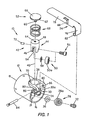
- a snake feed control device 10 in accordance with the present invention comprises a tubular housing 12 having an axis 14 and axially opposite front and rear ends 16 and 18, respectively.
- Housing 12 includes a wall 20 therein between ends 16 and 18 and transverse to axis 14, and wall 20 has front and rear sides not designated numerically, respectively facing front end 16 and rear end 18 of the housing.
- Wall 20 includes a passage 22 for receiving a snake 24 which is adapted to be axially fed relative to the device in the manner described in greater detail hereinafter.
- snake 24 is made of tightly wound spring wire and, in the embodiment illustrated, the wire at the free or outer end thereof is formed to provide an auger tip 26 which is radially enlarged relative to the remainder of the snake.
- Wall 20 includes roll mounting nodes 21 on the front side thereof, and feed device 10 further includes a pair of snake driving rolls 28 and 30 mounted on nodes 21 by socket head cap screws 32 and 34, respectively.
- a washer is interposed between each roll and the corresponding node as will be appreciated from the washer 36 illustrated in Figure 1 in connection with roll 28.
- Cap screws 32 and 34 provide axes of rotation for driving rolls 28 and 30, respectively, and each driving roll axis is skewed both horizontally and vertically relative to housing axis 14 and, preferably, at an angle of 30° with respect to each direction. It will be appreciated that the outer faces of nodes 21 are perpendicular to the corresponding driving roll axis.
- Driving rolls 28 and 30 have smooth outer surfaces 28a and 30a, respectively, and the skewed mounting thereof provides for driving snake 24 in a well known manner when the snake is rotated and displaced against the driving rolls.
- Housing 12 is provided inwardly adjacent front end 16 with a radially extending bore 38 having a bore axis 40 and an axially inner end which opens into snake passage 22.
- a snake drive actuating unit 42 is slidably and removably received in bore 38 and includes a drive actuating roll support member 44 having radially inner and outer ends 46 and 48, respectively, a drive actuating roll 50 mounted on inner end 46, and an operating member 52 mounted on outer end 48.
- inner end 46 of roll support member 44 is provided with an axially extending recess 54 receiving drive actuating roll 50 which is mounted in recess 54 by means of a socket head cap screw 56 and a washer 58, whereby roll 50 is rotatable about a drive actuating roll axis provided by cap screw 56.
- Operating member 52 includes a threaded stem 60 and an operating knob on the outer end thereof and having a peripheral edge 62 coaxial with axis 40 and having axially extending serrations or rolls, not designated numerically.
- Outer end 48 of roll support member 44 is provided with a threaded bore 64 which rotatably receives threaded stem 60, whereby the axial length of drive actuating unit 42 is adjustable by rotating operating member 52 relative to roll support member 44.
- the operating knob of member 52 has an axially outer surface 66 which is axially outwardly curved with respect to bore axis 40 and provides the outer end of drive actuating unit 42.
- drive actuating roll 50 provides the radially inner end of the drive actuating unit, and when the latter is received in bore 38, a compression spring 68 surrounds roll support member 44 and engages between the outer surface of housing 12 and the underside of the knob of operating member 52 to bias the drive actuating unit radially outwardly relative to the axis of housing 12.
- Drive actuating roll 50 is supported in housing 12 for the axis thereof to be skewed horizontally with respect to the housing axis, preferably at an angle of 30° relative thereto.
- an axially extending guide slot 70 is provided along bore 38 for receiving the outer end of a roll pin 72 which is mounted in an opening provided therefor in roll support member 44, not shown.
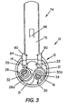
- Roll 50 has a smooth outer surface 50a and, as will be appreciated from Figure 2, snake driving rolls 28 and 30 and actuator drive roll 50 are equally spaced apart circumferentially about housing axis 14.
- Drive actuating unit 42 is adapted to be displaced radially inwardly of housing 12 against the bias of spring 68 by means of an operating lever 74 which includes a mounting leg 76 and a handle portion 78 extending generally perpendicular to the mounting leg.
- Front end 16 of housing 12 is provided with a pair of lever mounting ears 80 extending axially outwardly from end 16 at the radially outer end of bore 38, and mounting leg 76 is received between ears 80 for a rolled tubular lower end portion 82 thereof to receive a pivot pin 84 which extends through openings 86 provided therefor in ears 80.
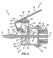
- Pin 84 provides a lever pivot axis transverse to and laterally spaced from both housing axis 14 and bore axis 40 and, as best seen in Figure 4-6, handle portion 78 of the lever normally extends across outer surface 66 of the operating knob of operating member 52 and slightly outwardly beyond rear end 18 of housing 12.
- handle portion 78 of lever 74 is provided with a latch element in the form of a finger 88 having a beveled outer end 90 for the purpose set forth hereinafter.
- Finger 88 is struck from the material of the handle portion to extend downwardly generally perpendicular thereto and, when lever 74 is in the position shown in Figure 4, finger 88 frictionally interengages with peripheral edge 62 of operating knob 52, whereby drive actuating unit 42 is releasably held in bore 38 by lever 74.
- drive actuating roll 50 is out of engagement with snake 24, and spring 68 biases lever 74 counterclockwise about pivot pin 84 so as to engage finger 88 radially inwardly against peripheral edge 62 of the operating knob.
- lever 74 By depressing handle portion 78 of lever 74 toward housing 12, the lever is pivoted clockwise about pin 84 to the position shown in Figure 5 in which drive actuating roll 50 engages snake 24 for the latter to be axially fed as will be described in greater detail hereinafter.
- lever 74 Such displacement of lever 74 presses handle portion 78 against outer surface 66 of the operating knob of member 52, whereby drive actuating unit 42 is displaced axially inwardly of bore 38 against the bias of spring 68 and finger 88 is displaced radially outwardly of peripheral edge 62.
- spring 68 biases operating member 52 radially outwardly of housing 12 to pivot lever 74 counterclockwise about pin 84, whereby finger 88 again frictionally interengages with peripheral edge 62 of the operating knob as shown in Figure 4 to releasably hold drive actuating unit 42 in bore 38.
- operating member 52 is rotatable relative to roll support member 44 so as to enable adjustment of the axial length of the drive actuating unit as defined by the innermost end of roll 50 and the outermost point on surface 66.
- Finger 88 on handle portion 78 of the lever in frictionally engaging peripheral edge 62 of the operating knob of member 52 restrains rotation thereof relative to roll support member 44 so as to preclude an unintended change in the length of the drive actuating unit.
- lever 74 is pivoted counterclockwise from the position shown in Figure 4 to disengage finger 88 from peripheral edge 62.
- spring 68 biases the drive actuating unit radially outwardly of housing 12 to the position shown in Figure 6 in which finger 88 engages outer surface 66 of the operating knob radially inwardly of peripheral edge 62 thereof.
- the operating knob can be freely rotated to adjust the length of the drive actuating unit, or the lever can be further pivoted counterclockwise to a position in which handle portion 78 is laterally offset from bore axis 40 and extends generally vertically relative to housing 12, as shown in Figure 3.
- drive actuating unit 42 is readily removable from bore 38 whereby, as will be appreciated from Figure 3, drive actuating roll 50 is displaced from its position intersecting snake passage 22. Accordingly, the latter can accommodate the enlarged auger portion 26 of snake 24 to facilitate the insertion or removal thereof from housing 12.
- lever 74 is adapted to be pivoted clockwise about pin 84 whereupon beveled outer end 90 of finger 88 interengages with outer surface 66 of the operating knob to displace drive actuating unit 42 radially inwardly of housing 12.
- finger 88 slides radially outwardly along surface 66 towards peripheral edge 62 of the operating knob.
- beveled end 90 of finger 88 moves across the upper extremity of peripheral edge 62, finger 88 moves downwardly and axially across edge 62 to again frictionally interengage the lever and operating knob to releasably hold the drive actuating unit in housing bore 38.
- feed control device 10 in accordance with the present invention is adapted to be attached to the axially outer end of a hand grip sleeve assembly 92 which corresponds structurally and functionally to hand grip sleeve assembly 60 in the drain cleaning apparatus disclosed in patent 4,956,889 to Kirk incorporated herein by reference. More particularly in this respect, rear end 18 of housing 12 is provided with diametrically opposed pairs of threaded openings 94 adapted to be aligned with corresponding openings provided in the outer end of sleeve assembly 92 for receiving threaded fasteners 96 by which feed control unit 10 is removably mountable on sleeve assembly 92.
- the snake driving rolls could be mounted on the housing for rotation about axes parallel to the housing axis and provided with helically grooved outer surfaces for cooperative engagement with the helically wound wire of the snake to achieve axial displacement of the latter relative to the housing upon displacement ofthe snake thereagainst.
- wall 20 can be axially thickened and provided with recesses for the snake driving rolls in place of the nodes which extend axially forwardly of the wall in the embodiment shown herein.
- the housing can be structured for support relative to the rotating snake of drain cleaning apparatus other than by mounting on the outer end of the hand grip assembly of a hand held power driven drain cleaning apparatus as disclosed herein.
Landscapes
- Engineering & Computer Science (AREA)
- Mechanical Engineering (AREA)
- Health & Medical Sciences (AREA)
- Life Sciences & Earth Sciences (AREA)
- Hydrology & Water Resources (AREA)
- Public Health (AREA)
- Water Supply & Treatment (AREA)
- Cleaning In General (AREA)
- Transmission Devices (AREA)
- Flexible Shafts (AREA)
- Finish Polishing, Edge Sharpening, And Grinding By Specific Grinding Devices (AREA)
Claims (53)
- Dispositif de contrôle de l'avance pour un outil de plomberie comprenant un serpentin flexible allongé (24) ayant un axe de serpentin, et un moyen destiné à mettre en rotation le serpentin (24) autour dudit axe, comprenant : un logement (12) comportant un axe de logement (14) et un passage (22) à travers celui-ci de manière axiale destiné à recevoir ledit serpentin (24), un moyen de rouleau d'entraínement du serpentin (28, 30) supporté sur ledit logement (12), un moyen d'actionnement de l'entraínement mobile radialement (42) supporté de manière amovible sur ledit logement (12) afin de déplacer ledit serpentin (24) contre ledit moyen de rouleau d'entraínement du serpentin (28, 30) ledit moyen d'actionnement de l'entraínement (42) ayant une extrémité externe radialement (48) caractérisé par un levier (74) monté de manière pivotante sur ledit logement (12) afin d'engager ladite extrémité externe et de déplacer radialement ledit moyen d'actionnement de l'entraínement (42) contre ledit serpentin (24) et ledit levier (74) et ladite extrémité externe (48) comprenant un moyen d'interengagement pour que ledit levier (74) maintienne de manière amovible ledit moyen d'actionnement de l'entraínement (42) sur ledit logement (12).
- Dispositif selon la revendication 1, caractérisé en ce que ledit moyen d'interengagement pour maintenir de manière amovible ledit moyen d'actionnement de l'entraínement (42) comprend un moyen de verrouillage sur ledit levier (74) qui engage par frottement ladite extrémité externe dudit moyen d'actionnement de l'entraínement (42).
- Dispositif selon la revendication 2, caractérisé en ce qu'il comprend en outre un moyen de ressort (68) qui pousse ledit moyen d'actionnement de l'entraínement (42) radialement vers l'extérieur pa rapport audit logement (12) pour que ladite extrémité externe s'engage contre ledit levier (74).
- Dispositif selon la revendication 3, caractérisé en ce que ladite extrémité externe comprend un élément de commande (52) transversal par rapport à la direction du déplacement radial dudit moyen d'actionnement de l'entraínement (42) et ayant un bord périphérique (62), ledit moyen de verrouillage s'engageant contre ledit bord périphérique (62).
- Dispositif selon la revendication 4, caractérisé en ce que ledit moyen de verrouillage comprend un doigt (88) sur ledit levier (74) qui s'étend depuis celui-ci généralement dans ladite direction.
- Dispositif selon la revendication 5, caractérisé en ce que ledit élément de commande (52) a une surface externe radialement (66) par rapport audit axe de logement (14), ladite surface (66) étant délimitée par ledit bord périphérique (62), et ledit levier (74) ayant des positions verrouillée et déverrouillée dans lesquelles ledit doigt (88) s'engage respectivement par frottement contre ledit bord périphérique (62) et recouvre ladite surface externe (66) vers l'intérieur dudit bord (62).
- Dispositif selon la revendication 6, caractérisé en ce que ladite surface externe (66) présente une courbure radialement vers l'extérieur par rapport audit axe de logement (14) et ledit doigt (88) à une extrémité qui engage ladite surface (66) dans ladite position déverrouillée, moyennant quoi ledit doigt (88) lors du déplacement dudit levier (74) de la position déverrouillée à la position verrouillée déplace ledit moyen d'actionnement de l'entraínement (42) radialement vers l'intérieur dudit logement (12) et ladite extrémité dudit doigt (88) se déplace radialement vers l'extérieur le long de ladite surface (66) vers ledit bord périphérique (62).
- Dispositif selon la revendication 7, caractérisé en ce que ladite extrémité dudit doigt (88) est pourvue d'un bord destiné à s'engager par glissement avec ladite surface externe (66) et un moyen de surface de came destiné à s'engager par glissement sur l'intersection dudit bord périphérique (62) avec ladite surface externe (66).
- Dispositif selon la revendication 1, caractérisé en ce que ledit logement (12) comprend un alésage radial (38) qui reçoit par glissement ledit moyen d'actionnement de l'entraínement (42), ledit levier (74) ayant une première position qui s'étend à travers ledit alésage (38), et une seconde position latéralement vers l'extérieur dudit alésage (38) et dans laquelle ledit moyen d'actionnement de l'entraínement (42) peut coulisser librement hors dudit alésage (38), ledit moyen s'interengageant pour que ledit levier (74) maintienne de manière amovible ledit moyen d'actionnement de l'entraínement (42) comprenant un moyen de verrouillage sur ledit levier (74) engageant par frottement ladite extrémité externe dudit moyen d'actionnement de l'entraínement (42) dans ladite première position dudit levier (74).
- Dispositif selon la revendication 9, caractérisé en ce que ladite extrémité externe comprend un élément de commande (52) transversal par rapport à la direction de déplacement radial dudit moyen d'actionnement de l'entraínement (42) et comportant un bord périphérique (62) et ledit moyen de verrouillage comprenant un doigt (88) sur ledit levier (74) s'engageant contre ledit bord périphérique (62) dans ladite première position dudit levier (74).
- Dispositif selon la revendication 10, caractérisé en ce qu'il comprend en outre un ressort de rappel (68) qui pousse ledit moyen d'actionnement de l'entraínement (42) radialement vers l'extérieur par rapport audit alésage (38), ledit élément de commande (52) comportant une surface externe (66), et ledit levier (74) ayant une troisième position entre lesdites première et seconde positions dans laquelle ledit doigt (88) s'engage contre ladite surface externe (66) dudit élément de commande (52) radialement vers l'intérieur dudit bord périphérique (62), moyennant quoi ledit bord (88) lors du déplacement dudit levier (74) de ladite troisième à ladite première position glisse radialement vers l'extérieur le long de ladite surface externe (66) et déplace ledit moyen d'actionnement de l'entraínement (42) radialement vers l'intérieur par rapport audit alésage (38) contre la force dudit ressort (68).
- Dispositif selon la revendication 11, caractérisé en ce que ledit doigt (88) comporte une extrémité engageant ladite surface externe (66) dans ladite troisième position dudit levier (74), ladite extrémité dudit doigt (88) et ladite surface externe (66) ayant des profiles destinés à favoriser le coulissement radial vers l'extérieur dudit doigt (88) de ladite troisième à ladite première position.
- Dispositif selon la revendication 12, caractérisé en ce que ladite surface externe (66) est incurvée vers l'extérieur par rapport audit axe de logement (14) et ladite extrémité dudit doigt (88) comprend un bord pour un engagement par glissement avec ladite surface externe (66) et une surface de came pour un engagement par glissement sur l'intersection de ladite surface externe (66) et dudit bord périphérique (62).
- Dispositif selon la revendication 13, caractérisé en ce que ledit moyen de rouleau d'entraínement du serpentin comprend une paire de rouleaux d'entraínement du serpentin (28, 30) montés chacun sur ledit logement (12) pour effectuer une rotation autour d'un axe de rouleau d'entraínement et ledit moyen d'actionnement de l'entraínement comprend un rouleau d'actionnement de l'entraínement (50) qui fournit ladite extrémité interne et qui peut être mis en rotation autour d'un axe du rouleau d'actionnement.
- Dispositif selon la revendication 14, caractérisé en ce que chacun parmi ledit axe de rouleau d'entraínement et ledit axe de rouleau d'actionnement est en biais par rapport audit axe de logement et chacun parmi lesdits rouleaux d'entraínement du serpentin (28, 30) et ledit rouleau d'actionnement (50) a une surface externe lisse (28a, 30a, 50a).
- Dispositif selon la revendication 1, caractérisé en ce qu'il comprend en outre un moyen (68) destiné à pousser ledit moyen d'actionnement de l'entraínement (42) radialement vers l'extérieur par rapport audit passage (22).
- Dispositif selon la revendication 1, caractérisé en ce que ledit moyen de rouleau d'entraínement du serpentin comprend une paire de rouleaux d'entraínement du serpentin (28, 30) montés chacun sur ledit logement (12) pour effectuer une rotation autour d'un axe de rouleau d'entraínement fixé radialement par rapport audit passage (22).
- Dispositif selon la revendication 17, caractérisé en ce que chaque axe de rouleau d'entraínement est en biais par rapport audit axe de logement (14).
- Dispositif selon la revendication 18, caractérisé en ce que chacun parmi lesdits rouleaux d'entraínement du serpentin (28, 30) a une surface externe lisse (28a, 30a).
- Dispositif selon la revendication 17, caractérisé en ce que ledit moyen d'actionnement de l'entraínement (42) comprend un rouleau d'actionnement de l'entraínement (50) qui fournit une extrémité interne radialement de celui-ci et qui peut être mis en rotation autour d'un axe du rouleau d'actionnement.
- Dispositif selon la revendication 20, caractérisé en ce que chacun parmi ledit axe de rouleau d'entraínement et ledit axe de rouleau d'actionnement est en biais par rapport audit axe de logement (14) et chacun parmi lesdits rouleaux d'entraínement du serpentin (28, 30) et ledit rouleau d'actionnement (50) a une surface externe lisse (28a, 30a, 50a).
- Dispositif selon la revendication 1, caractérisé en ce que ledit moyen d'actionnement de l'entraínement (42) comporte une extrémité interne radialement, et comprend un moyen destiné à ajuster la distance entre ses extrémités interne et externe radialement.
- Dispositif selon la revendication 22, caractérisé en ce que ledit moyen d'actionnement de l'entraínement (42) comprend des premier et second éléments (44, 52), et un moyen qui interconnecte lesdits premier et second éléments (44, 52) pour un déplacement l'un par rapport à l'autre afin d'ajuster la distance entre lesdites extrémités interne et externe.
- Dispositif selon la revendication 23, caractérisé en ce que ledit moyen qui interconnecte lesdits premier et second éléments (44, 52) comprend un moyen de filetage (60, 64).
- Dispositif selon la revendication 24, caractérisé en ce que ledit premier élément (44) comprend un alésage fileté (64) et un second élément (52) comprend une tige filetée (60) insérée par rotation dans ledit alésage (64).
- Dispositif selon la revendication 23, caractérisé en ce que ledit logement (12) comprend un alésage radial (38) recevant par glissement ledit premier élément (44), et un moyen de ressort (68) entre ledit logement (12) et ledit second élément (52) destiné à pousser ledit moyen d'actionnement de l'entraínement (42) radialement vers l'extérieur par rapport audit alésage (38).
- Dispositif selon la revendication 26, caractérisé en ce que ledit second élément (52) et ledit levier (74) comprennent ledit moyen d'interengagement afin de limiter un déplacement radial vers l'extérieur dudit moyen d'actionnement de l'entraínement (42).
- Dispositif selon la revendication 27, caractérisé en ce que ledit moyen qui interconnecte lesdits premier et second éléments (44, 52) comprend un alésage fileté (64) dans ledit premier élément (44) et une tige filetée (60) sur ledit second élément (52) insérée par rotation dans ledit alésage (64), ladite tige (60) ayant un pommeau sur celle-ci afin de mettre en rotation ledit second élément (52) par rapport audit premier élément (44), ledit pommeau constituant ladite extrémité externe dudit moyen d'actionnement de l'entraínement (42).
- Dispositif selon la revendication 28, caractérisé en ce que ledit moyen qui interengage ledit second élément (52) et ledit levier (74) sont des moyens qui s'interengagent avec ledit pommeau afin de limiter un déplacement radial vers l'extérieur dudit moyen d'actionnement de l'entraínement (42).
- Dispositif selon la revendication 29, caractérisé en ce que ledit moyen qui s'interengage avec ledit pommeau le fait de manière amovible afin de libérer ledit moyen d'actionnement de l'entraínement (42) pour être retiré dudit alésage radial (38).
- Dispositif selon la revendication 27, caractérisé en ce que ledit moyen qui interengage ledit second élément (52) et ledit levier (74) comprend un moyen sur ledit moyen de levier (74) qui s'interengage de façon amovible avec ledit second élément (52) afin de libérer ledit moyen d'actionnement de l'entraínement (42) pour être retiré dudit alésage radial (38).
- Dispositif selon la revendication 26, caractérisé en ce que ladite extrémité interne dudit moyen d'actionnement de l'entraínement (42) comprend un rouleau d'actionnement de l'entraínement (50) monté sur ledit premier élément (44) pour effectuer une rotation autour d'un axe de rouleau d'actionnement.
- Dispositif selon la revendication 32, caractérisé en ce que ledit moyen de rouleau d'entraínement du serpentin (28, 30) comprend une paire de rouleaux d'entraínement du serpentin montés chacun sur ledit logement (12) pour effectuer une rotation autour d'un axe de rouleau d'entraínement fixé radialement par rapport audit passage (22).
- Dispositif selon la revendication 33, caractérisé en ce que chacun parmi ledit axe de rouleau d'entraínement et ledit axe de rouleau d'actionnement est en biais par rapport audit axe de logement (14) et chacun parmi lesdits rouleaux d'entraínement du serpentin (28, 30) et ledit rouleau d'actionnement (50) a une surface externe lisse (28a, 30a, 50a).
- Dispositif selon la revendication 34, caractérisé en ce que ledit moyen qui interconnecte lesdits premier et second éléments (44, 52) comprend un alésage fileté (64) dans ledit premier élément (44) et une tige filetée (60) sur ledit second élément (52) inséré par rotation dans ledit alésage (64), ladite tige (60) ayant un pommeau sur celle-ci pour mettre en rotation ledit second élément (52) par rapport audit premier élément (44), ledit pommeau constituant ladite externe dudit moyen d'actionnement de l'entraínement (42).
- Dispositif selon la revendication 35, caractérisé en ce que ledit pommeau possède un bord périphérique (62) et ledit levier (74) comprend un doigt (88) qui s'interengage de manière amovible avec ledit bord (62) afin de limiter un déplacement radial vers l'extérieur dudit moyen d'actionnement de l'entraínement (42) et de libérer ledit moyen d'actionnement de l'entraínement (42) pour être retirer dudit alésage radial (38).
- Dispositif selon la revendication 1, caractérisé en ce que le logement (12) est tubulaire et a des extrémités opposées axialement (16, 18) et une paroi (20) entre lesdites extrémités (16, 18) à travers laquelle ledit passage (22) s'étend, ledit moyen de rouleau d'entraínement du serpentin comporte une paire de rouleaux d'entraínement du serpentin (28, 30) supportés chacun sur ladite paroi (20) pour effectuer une rotation autour d'un axe de rouleau d'entraínement correspondant et comportant une surface périphérique (28a, 30a) qui coupe ledit passage (22), un alésage radial (38) dans ledit logement (12) ayant un axe d'alésage (40) et une ouverture d'extrémité interne dans ledit passage (22), ledit moyen d'actionnement de l'entraínement (42) étant inséré à coulissement dans ledit alésage (38) et ayant un rouleau d'actionnement de l'entraínement (50) qui constitue une extrémité interne radialement dudit moyen d'actionnement de l'entraínement (42) et pouvant être mis en rotation autour d'un axe de rouleau d'actionnement, ledit levier (74) étant monté sur ledit logement (12) à proximité de l'une parmi lesdites extrémités opposées (16, 18) pour un déplacement par pivotement dans des directions opposées autour d'un axe de levier transversal par rapport à et écarté latéralement dudit axe d'alésage (40), ledit levier (74) comprenant une partie de poignée (78) s'étendant axialement dudit logement (12) depuis ladite une extrémité sur ladite extrémité externe dudit moyen d'actionnement (42), moyennant quoi un déplacement de ladite partie de poignée (78) radialement vers ledit logement (12) déplace ledit moyen d'actionnement de l'entraínement (42) radialement vers l'intérieur par rapport audit passage (22) afin d'engager ledit serpentin (24) contre lesdits rouleaux d'entraínement du serpentin (28, 30) et comprenant un moyen de ressort (68) destiné à pousser ledit moyen d'actionnement de l'entraínement (42) radialement vers l'extérieur par rapport audit passage (22) afin de dégager ledit serpentin (24) desdits rouleaux d'entraínement du serpentin (28, 30).
- Dispositif selon la revendication 37, caractérisé en ce que chacun parmi ledit axe de rouleau d'entraínement et ledit axe de rouleau d'actionnement (14) est en biais par rapport audit axe de logement et chacun parmi lesdits rouleaux d'entraínement du serpentin (28, 30) et ledit rouleau d'actionnement de l'entraínement (50) a une surface externe lisse (28a, 30a, 50a).
- Dispositif selon la revendication 37, caractérisé en ce que ledit moyen d'actionnement de l'entraínement (42) est inséré de manière amovible dans ledit alésage (38) et ladite extrémité externe de celui-ci et ladite partie de poignée (78) dudit levier (74) comprend un moyen d'interengagement destiné à maintenir de manière amovible ledit moyen d'actionnement de l'entraínement (42) dans ledit alésage (38).
- Dispositif selon la revendication 37, caractérisé en ce que ledit moyen d'actionnement de l'entraínement (42) comprend un moyen destiné à ajuster de manière sélective la distance entre lesdites extrémités radialement interne et externe de celui-ci.
- Dispositif selon la revendication 37, caractérisé en ce que lesdites extrémités opposées (16, 18) dudit logement (12) sont des extrémités avant et arrière, ladite paroi (20) ayant un côté avant faisant face à ladite extrémité avant (16), un moyen d'arbre d'axe qui supporte de manière amovible ladite paire de rouleaux d'entraínement du serpentin (28, 30) sur ledit côté avant de ladite paroi (20), et ledit moyen d'arbre d'axe étant accessible par l'intermédiaire de ladite extrémité avant (16) dudit logement (12) pour un retrait.
- Dispositif selon la revendication 37, caractérisé en ce que ledit moyen d'actionnement de l'entraínement (42) est inséré de manière amovible dans ledit alésage (38) et ladite extrémité externe de celui-ci comprend une surface externe axialement (66) qui recouvre ladite partie de poignée (78) dudit levier (74), ladite surface externe (66) étant délimitée par un bord périphérique (62) qui s'étend axialement par rapport audit axe d'alésage (40), et ladite partie de poignée (78) comprenant un élément de verrouillage (88) et ayant une position verrouillée dans laquelle ledit élément de verrouillage (88) s'engage par frottement avec ledit bord périphérique (62) afin d'interengager de manière amovible ledit levier (74) et ladite unité d'actionnement de l'entraínement (42).
- Dispositif selon la revendication 42, caractérisé en ce que ladite partie de poignée (78) dudit levier (74) peut être déplacée radialement dans un sens opposé dudit logement (12) jusqu'à une seconde position dans laquelle ledit élément de verrouillage (88) dégage ledit bord (62) et ladite partie de poignée (78) est latéralement vers l'extérieur dudit alésage (38), moyennant quoi ledit moyen d'actionnement de l'entraínement (42) peut être glissé hors dudit alésage (38).
- Dispositif selon la revendication 43, caractérisé en ce que ledit élément de verrouillage (88) est un doigt qui s'étend depuis ladite partie de poignée (78).
- Dispositif selon la revendication 44, caractérisé en ce que ladite partie de poignée (78) dudit levier (74) peut être déplacée jusqu'à une troisième position entre ladite position verrouillée et ladite seconde position, ledit doigt (88) dans ladite troisième position s'engageant contre ladite surface radialement externe (66) radialement vers l'intérieur dudit bord (62), et ledit doigt (88) et ladite surface externe (66) s'interengageant pour un déplacement de ladite partie de poignée (78) radialement vers ledit logement (12) depuis ladite troisième position afin de déplacer ledit moyen d'actionnement de l'entraínement (42) axialement vers l'intérieur par rapport audit alésage (38) et pour déplacer ledit doigt (88) radialement vers l'extérieur et sur ledit bord périphérique (62) jusqu'à une position verrouillée.
- Dispositif selon la revendication 37, caractérisé en ce que ledit moyen d'actionnement de l'entraínement (42) comprend un élément de support (44) du rouleau d'actionnement de l'entraínement ayant des extrémités interne et externe radialement (46, 48) et un élément de commande (52) sur ladite extrémité externe (48) et interengagé de manière filetée avec celui-ci, ledit rouleau d'actionnement de l'entraínement (50) étant monté sur ladite extrémité interne (46) dudit élément de support (44) et ledit élément de commande (52) ayant une extrémité externe comprenant un pommeau de commande constituant ladite extrémité externe dudit moyen d'actionnement (42), ledit élément de commande (52) pouvant être mis en rotation par rapport audit élément de support (44) par ledit pommeau afin d'ajuster la distance entre lesdites extrémités interne et externe dudit moyen d'actionnement de l'entraínement (42).
- Dispositif selon la revendication 46, caractérisé en ce que ledit moyen de ressort (68) comprend un ressort de compression qui entoure ledit élément de support de rouleau (44) et ayant des extrémités opposées dont l'une s'engage avec ledit logement (12) et l'autre avec ledit pommeau.
- Dispositif selon la revendication 37, caractérisé en ce que ledit moyen d'actionnement de l'entraínement (42) est inséré de façon amovible dans ledit alésage (38) et comprend un élément de support (44) du rouleau d'actionnement de l'entraínement ayant des extrémités interne et externe axialement (46, 48) par rapport audit alésage (38) et un élément de commande (52) monté par rotation sur ladite extrémité externe (48), ledit rouleau d'action de l'entraínement (50) étant monté sur ladite extrémité interne (46) dudit élément de support (44), ledit élément de commande (52) comprenant un pommeau ayant une surface externe axialement (66) constituant ladite extrémité externe dudit moyen d'actionnement de l'entraínement (42) et un bord périphérique (62) coaxial avec ledit axe d'alésage (40) et délimitant ladite surface (66), ledit élément de commande (52) et ladite extrémité externe (48) dudit élément de support (44) étant interengagés par filetage pour la rotation dudit pommeau afin d'ajuster axialement la distance entre lesdites extrémités interne et externe dudit moyen d'actionnement (42), ladite partie de poignée (78) dudit levier (74) comprenant un élément de verrouillage (88) et ledit levier (74) ayant des première et seconde positions dans lesquelles ladite partie de poignée (78) recouvre respectivement ladite surface externe axialement (66) dudit pommeau et est écarté latéralement de l'extérieur dudit alésage (38), ledit élément de verrouillage (88) dans ladite première position interengageant par frottement ledit bord périphérique (62) afin de restreindre la rotation dudit pommeau et de maintenir de manière amovible ledit moyen d'actionnement de l'entraínement (42) dans ledit alésage (38), et ladite partie de poignée (78) dans ladite seconde position découvrant ledit moyen d'actionnement (42) pour être retirée dudit alésage (38).
- Dispositif selon la revendication 48, caractérisé en ce que ledit élément de verrouillage (88) est un doigt s'étendant axialement dudit alésage (40) lorsque ledit levier (74) se trouve dans ladite première position, ledit doigt (88) ayant une extrémité écartée de ladite partie de poignée (78), ledit levier (74) ayant une troisième position entre lesdites première et seconde positions et dans laquelle ladite extrémité dudit doigt (88) engage ladite surface externe axialement (66) dudit pommeau radialement vers l'intérieur dudit bord périphérique (62), ladite extrémité dudit doigt (88) et de ladite surface externe (66) s'interengageant pour le déplacement dudit levier (74) depuis ladite troisième jusqu'à ladite première position afin de déplacer ledit moyen d'actionnement (42) axialement vers l'intérieur dudit alésage (38) et ledit doigt (88) radialement vers l'extérieur le long de ladite surface externe (66) et sur ledit bord périphérique (62).
- Dispositif selon la revendication 49, caractérisé en ce que ledit moyen de ressort (68) comprend un ressort de compression entourant ledit élément de support de rouleau (44) et ayant des extrémités opposées dont l'une s'engage avec ledit logement (12) et l'autre avec ledit pommeau.
- Dispositif selon la revendication 50, caractérisé en ce que lesdites extrémités opposées (16, 18) dudit logement (12) sont des extrémités avant et arrière, ladite paroi (20) ayant un côté avant faisant face à ladite extrémité avant (16), un moyen d'arbre d'axe supportant de manière amovible ladite paire de rouleaux d'entraínement du serpentin (28, 30) sur ledit côté avant de ladite paroi (20), et ledit moyen d'arbre d'axe étant accessible par l'intermédiaire de ladite extrémité avant (16) dudit logement (12) pour un retrait.
- Dispositif selon la revendication 51, caractérisé en ce que ladite une parmi lesdites extrémités opposées (16, 18) est ladite extrémité avant (16) et ledit levier (74) comprend une partie de patte (76) qui s'étend généralement de manière perpendiculaire depuis ladite partie de poignée (78) et ayant une extrémité (82) écartée de ladite partie de poignée, ladite extrémité de ladite partie de patte (76) étant montée de manière pivotante sur ladite extrémité avant (16) dudit logement (12) afin de constituer ledit axe de levier.
- Dispositif selon la revendication 52, caractérisé en ce que chacun parmi ledit axe de rouleau d'entraínement et ledit axe de rouleau d'actionnement est en biais par rapport audit axe de logement (14) et chacun parmi lesdits rouleaux d'entraínement du serpentin (28, 30) et ledit rouleau d'actionnement de l'entraínement (50) a une surface externe lisse (28a, 30a, 50a).
Priority Applications (2)
| Application Number | Priority Date | Filing Date | Title |
|---|---|---|---|
| EP05103180A EP1574630B1 (fr) | 1997-07-28 | 1998-06-26 | Dispositif de contrôle de l'avance pour outils de plombier |
| EP05103177A EP1568825B1 (fr) | 1997-07-28 | 1998-06-26 | Dispositif de contrôle de l'avance pour outils de plombier |
Applications Claiming Priority (2)
| Application Number | Priority Date | Filing Date | Title |
|---|---|---|---|
| US08/901,653 US5901401A (en) | 1997-07-28 | 1997-07-28 | Feed control device for plumbing tools |
| US901653 | 1997-07-28 |
Related Child Applications (2)
| Application Number | Title | Priority Date | Filing Date |
|---|---|---|---|
| EP05103180A Division EP1574630B1 (fr) | 1997-07-28 | 1998-06-26 | Dispositif de contrôle de l'avance pour outils de plombier |
| EP05103177A Division EP1568825B1 (fr) | 1997-07-28 | 1998-06-26 | Dispositif de contrôle de l'avance pour outils de plombier |
Publications (3)
| Publication Number | Publication Date |
|---|---|
| EP0894906A2 EP0894906A2 (fr) | 1999-02-03 |
| EP0894906A3 EP0894906A3 (fr) | 1999-09-15 |
| EP0894906B1 true EP0894906B1 (fr) | 2005-04-27 |
Family
ID=25414593
Family Applications (3)
| Application Number | Title | Priority Date | Filing Date |
|---|---|---|---|
| EP05103180A Expired - Lifetime EP1574630B1 (fr) | 1997-07-28 | 1998-06-26 | Dispositif de contrôle de l'avance pour outils de plombier |
| EP98630030A Expired - Lifetime EP0894906B1 (fr) | 1997-07-28 | 1998-06-26 | Dispositif de contrôle de l'avance pour outils de plombier |
| EP05103177A Expired - Lifetime EP1568825B1 (fr) | 1997-07-28 | 1998-06-26 | Dispositif de contrôle de l'avance pour outils de plombier |
Family Applications Before (1)
| Application Number | Title | Priority Date | Filing Date |
|---|---|---|---|
| EP05103180A Expired - Lifetime EP1574630B1 (fr) | 1997-07-28 | 1998-06-26 | Dispositif de contrôle de l'avance pour outils de plombier |
Family Applications After (1)
| Application Number | Title | Priority Date | Filing Date |
|---|---|---|---|
| EP05103177A Expired - Lifetime EP1568825B1 (fr) | 1997-07-28 | 1998-06-26 | Dispositif de contrôle de l'avance pour outils de plombier |
Country Status (7)
| Country | Link |
|---|---|
| US (1) | US5901401A (fr) |
| EP (3) | EP1574630B1 (fr) |
| JP (1) | JP4180696B2 (fr) |
| CN (1) | CN1095055C (fr) |
| CA (1) | CA2228868C (fr) |
| DE (3) | DE69829920T2 (fr) |
| ES (3) | ES2241110T3 (fr) |
Cited By (3)
| Publication number | Priority date | Publication date | Assignee | Title |
|---|---|---|---|---|
| DE102008015532A1 (de) | 2008-03-25 | 2009-10-08 | Rothenberger Ag | Reinigungsgerät für die Reinigung von Rohrleitungen |
| EP2277634A1 (fr) | 2009-07-24 | 2011-01-26 | Rothenberger AG | Appareil de nettoyage pour le nettoyage de conduites |
| DE202008018563U1 (de) | 2008-03-25 | 2015-11-03 | Rothenberger Ag | Reinigungsgerät für die Reinigung von Rohrleitungen |
Families Citing this family (40)
| Publication number | Priority date | Publication date | Assignee | Title |
|---|---|---|---|---|
| US6158076A (en) * | 1999-02-22 | 2000-12-12 | Emerson Electric Co. | Feed control devices for hand operated drain cleaning tools |
| US6470525B1 (en) * | 1999-11-30 | 2002-10-29 | Arthur A. Silverman | Drain cleaning apparatus having remote power feed |
| US6343398B1 (en) * | 2000-04-13 | 2002-02-05 | General Wire Spring Company | Drain cleaning apparatus with feed control |
| US6615436B1 (en) * | 2000-09-11 | 2003-09-09 | Emerson Electric Co. | Powered drain cleaner |
| US6637064B2 (en) | 2001-01-02 | 2003-10-28 | Lee H. Silverman | Drain cleaning apparatus with remotely adjustable feed control |
| US6655228B1 (en) * | 2001-07-06 | 2003-12-02 | Spartan Tool, L.L.C. | Dual directional power feed |
| US20040255415A1 (en) * | 2003-06-23 | 2004-12-23 | Ralph Silva | Cable feeding device |
| US7478451B2 (en) * | 2004-03-04 | 2009-01-20 | Emerson Electric Co. | Feed control device for plumbing tools |
| US7685669B2 (en) * | 2004-03-04 | 2010-03-30 | Emerson Electric Co. | Feed control device for plumbing tools |
| EP1931907A1 (fr) * | 2005-09-14 | 2008-06-18 | Sydney Water Corporation | Dispositif de fixation pour système de nettoyage de tuyau d'égout |
| NL1031314C2 (nl) * | 2006-03-07 | 2007-09-10 | Rior | Veertransporteur voor een afvoerreinigingsapparaat. |
| JP5247136B2 (ja) * | 2007-12-20 | 2013-07-24 | 中央発條株式会社 | ケーブル式操作装置及びケーブルガイド用コイルバネ |
| JP2011036769A (ja) * | 2009-08-07 | 2011-02-24 | Meiji Kikai Seisakusho:Kk | スプレーガン |
| US8887343B2 (en) * | 2010-03-12 | 2014-11-18 | Stoneage, Inc. | System for propelling a coil clad hose and method thereof |
| DE102012112599A1 (de) * | 2011-12-21 | 2013-06-27 | Emerson Electric Co. | Vorschubsteuersperre für manuell bedienten Abflussreiniger |
| US8826483B2 (en) | 2011-12-21 | 2014-09-09 | Emerson Electric Co. | Feed control lock for hand operated drain cleaner |
| US9550649B2 (en) | 2013-05-30 | 2017-01-24 | Stoneage, Inc. | Apparatus for propelling a coil clad hose |
| US10071401B2 (en) | 2014-12-23 | 2018-09-11 | Ridge Tool Company | Feed control device for plumbing tools |
| DE102015103349A1 (de) * | 2015-03-06 | 2016-09-08 | Rothenberger Ag | Vorschubeinheit für eine Rohrreinigungsmaschine, insbesondere Trommel-Rohrreinigungsmaschine |
| EP3387194B1 (fr) | 2015-12-09 | 2024-05-29 | Milwaukee Electric Tool Corporation | Dégorgeoir |
| TWM555907U (zh) | 2016-02-17 | 2018-02-21 | 米沃奇電子工具公司 | 衛浴用螺旋鑽 |
| US10626593B2 (en) | 2016-04-05 | 2020-04-21 | Black & Decker Inc. | Powered drain auger |
| US10189060B2 (en) * | 2016-04-20 | 2019-01-29 | Sdy International Co., Ltd. | Cable feeding device for drain cleaner |
| WO2017192289A1 (fr) * | 2016-05-05 | 2017-11-09 | Stoneage, Inc. | Appareil d'entraînement à courroie sans fin pour lance de nettoyage de tube flexible |
| CN107663886B (zh) | 2016-07-27 | 2020-12-04 | 米沃奇电动工具公司 | 用于排水管清洁器的缆绳进给控制机构 |
| US10704250B2 (en) | 2016-10-28 | 2020-07-07 | Milwaukee Electric Tool Corporation | Sewer cleaning machine |
| US10722928B2 (en) | 2016-11-28 | 2020-07-28 | Milwaukee Electric Tool Corporation | Drain cleaner |
| USD830806S1 (en) | 2017-02-15 | 2018-10-16 | Black & Decker Inc. | Drain auger |
| US9683360B1 (en) * | 2017-02-23 | 2017-06-20 | Daisval Vigoa | Automated pipe clearer |
| US10519646B2 (en) | 2017-10-27 | 2019-12-31 | Tti (Macao Commercial Offshore) Limited | Cable feed mechanism for a drain cleaner |
| EP3735497B1 (fr) | 2018-01-05 | 2026-03-04 | Milwaukee Electric Tool Corporation | Machine de nettoyage d'égouts |
| US11505229B2 (en) | 2018-04-13 | 2022-11-22 | Milwaukee Electric Tool Corporation | Tool support |
| US10612230B2 (en) * | 2018-06-28 | 2020-04-07 | Sdy International Co., Ltd. | Cable control device for pipeline cleaner |
| WO2020033626A1 (fr) * | 2018-08-10 | 2020-02-13 | Milwaukee Electric Tool Corporation | Machine de nettoyage de canalisations |
| EP3849718B1 (fr) | 2018-09-11 | 2025-03-19 | Milwaukee Electric Tool Corporation | Déboucheur |
| WO2020215059A1 (fr) | 2019-04-19 | 2020-10-22 | Milwaukee Electric Tool Corporation | Mécanisme d'alimentation pour ensemble de nettoyage de drain |
| WO2020231966A1 (fr) | 2019-05-15 | 2020-11-19 | Milwaukee Electric Tool Corporation | Dispositif de nettoyage de drains |
| US12409478B2 (en) | 2019-06-10 | 2025-09-09 | Milwaukee Electric Tool Corporation | Transportable machine including a track system |
| CN118357222B (zh) * | 2024-06-19 | 2024-09-03 | 洛阳信成精密机械有限公司 | 一种激光清洗装置及其清洗方法 |
| KR102835660B1 (ko) * | 2024-12-13 | 2025-07-23 | 주식회사 대현드래곤트레이딩 | 관로 막힘 제거용 관로 천공 장치 |
Family Cites Families (20)
| Publication number | Priority date | Publication date | Assignee | Title |
|---|---|---|---|---|
| US550762A (en) * | 1895-12-03 | murphy | ||
| US2600707A (en) * | 1949-04-15 | 1952-06-17 | James E Turnbaugh | Flexible rotary reaming apparatus |
| US3224024A (en) * | 1964-03-23 | 1965-12-21 | Marco Products Co | Feed means for plumbers' tool |
| US3449782A (en) * | 1967-09-15 | 1969-06-17 | Lawrence Irwin F | Grip handle chuck |
| US3451089A (en) * | 1967-11-06 | 1969-06-24 | Conco Inc | Conduit cleaning apparatus |
| US3691583A (en) * | 1971-01-06 | 1972-09-19 | Gen Wire Spring Co | Sewer augering machine |
| US3703015A (en) * | 1971-08-25 | 1972-11-21 | Lester H Naeve | Conduit cleaning apparatus |
| US3882565A (en) * | 1973-11-30 | 1975-05-13 | Lawrence F Irwin | Spring feed device |
| US4153966A (en) * | 1978-06-12 | 1979-05-15 | Lawrence Irwin F | Spring feed device |
| US4218802A (en) * | 1979-03-14 | 1980-08-26 | Emerson Electric Co. | Drain cleaning apparatus |
| US4395791A (en) * | 1980-03-03 | 1983-08-02 | Lawrence Irwin F | Spring feeding mechanism |
| US4580306A (en) * | 1984-01-19 | 1986-04-08 | Lawrence Irwin F | Waste line cleanout apparatus |
| US4686732A (en) * | 1984-01-19 | 1987-08-18 | Lawrence Irwin F | Waste line cleanout apparatus |
| US4956889A (en) * | 1989-07-03 | 1990-09-18 | Emerson Electric Co. | Portable drain cleaning apparatus |
| US5029356A (en) * | 1989-09-25 | 1991-07-09 | General Wire Spring Company | Sewer augering apparatus |
| US5031276A (en) * | 1990-02-20 | 1991-07-16 | Emerson Electric Co. | Drain cleaning machine |
| US5031263A (en) * | 1990-02-20 | 1991-07-16 | Emerson Electric Co. | Drain cleaning machine |
| US5239724A (en) * | 1992-01-30 | 1993-08-31 | Spartan Tool | Mechanism for advancing a rotating cylindrical member |
| US5507062A (en) * | 1995-03-24 | 1996-04-16 | Spartan Tool Div. Of Pettibone Corp. | Sealing structure on a mechanism for advancing a rotating cylindrical member |
| US5640736A (en) * | 1995-09-12 | 1997-06-24 | Pettibone Corporation | Power feed device for hand held drain and sewer cleaner |
-
1997
- 1997-07-28 US US08/901,653 patent/US5901401A/en not_active Expired - Lifetime
-
1998
- 1998-03-09 CA CA002228868A patent/CA2228868C/fr not_active Expired - Fee Related
- 1998-06-23 CN CN98115047A patent/CN1095055C/zh not_active Expired - Fee Related
- 1998-06-26 DE DE69829920T patent/DE69829920T2/de not_active Expired - Lifetime
- 1998-06-26 EP EP05103180A patent/EP1574630B1/fr not_active Expired - Lifetime
- 1998-06-26 EP EP98630030A patent/EP0894906B1/fr not_active Expired - Lifetime
- 1998-06-26 DE DE69840762T patent/DE69840762D1/de not_active Expired - Lifetime
- 1998-06-26 ES ES98630030T patent/ES2241110T3/es not_active Expired - Lifetime
- 1998-06-26 ES ES05103177T patent/ES2320147T3/es not_active Expired - Lifetime
- 1998-06-26 DE DE69840487T patent/DE69840487D1/de not_active Expired - Lifetime
- 1998-06-26 ES ES05103180T patent/ES2324303T3/es not_active Expired - Lifetime
- 1998-06-26 EP EP05103177A patent/EP1568825B1/fr not_active Expired - Lifetime
- 1998-07-27 JP JP21064798A patent/JP4180696B2/ja not_active Expired - Fee Related
Cited By (4)
| Publication number | Priority date | Publication date | Assignee | Title |
|---|---|---|---|---|
| DE102008015532A1 (de) | 2008-03-25 | 2009-10-08 | Rothenberger Ag | Reinigungsgerät für die Reinigung von Rohrleitungen |
| DE102008015532B4 (de) * | 2008-03-25 | 2014-08-07 | Rothenberger Ag | Reinigungsgerät für die Reinigung von Rohrleitungen |
| DE202008018563U1 (de) | 2008-03-25 | 2015-11-03 | Rothenberger Ag | Reinigungsgerät für die Reinigung von Rohrleitungen |
| EP2277634A1 (fr) | 2009-07-24 | 2011-01-26 | Rothenberger AG | Appareil de nettoyage pour le nettoyage de conduites |
Also Published As
| Publication number | Publication date |
|---|---|
| CA2228868C (fr) | 2003-09-09 |
| CN1206804A (zh) | 1999-02-03 |
| ES2241110T3 (es) | 2005-10-16 |
| DE69840762D1 (de) | 2009-05-28 |
| DE69840487D1 (de) | 2009-03-05 |
| EP1574630B1 (fr) | 2009-04-15 |
| ES2320147T3 (es) | 2009-05-19 |
| DE69829920T2 (de) | 2006-05-04 |
| JP4180696B2 (ja) | 2008-11-12 |
| EP1568825A1 (fr) | 2005-08-31 |
| ES2324303T3 (es) | 2009-08-04 |
| CA2228868A1 (fr) | 1999-01-28 |
| EP1568825B1 (fr) | 2009-01-14 |
| EP0894906A2 (fr) | 1999-02-03 |
| US5901401A (en) | 1999-05-11 |
| JPH11104588A (ja) | 1999-04-20 |
| EP1574630A1 (fr) | 2005-09-14 |
| DE69829920D1 (de) | 2005-06-02 |
| EP0894906A3 (fr) | 1999-09-15 |
| CN1095055C (zh) | 2002-11-27 |
Similar Documents
| Publication | Publication Date | Title |
|---|---|---|
| US5901401A (en) | Feed control device for plumbing tools | |
| EP1031666B1 (fr) | Outil manuel de nettoyage pour conduits | |
| US6412136B1 (en) | Drain cleaning apparatus | |
| US6615436B1 (en) | Powered drain cleaner | |
| US6360397B1 (en) | Feed control device for plumbing apparatus | |
| US4956889A (en) | Portable drain cleaning apparatus | |
| US4580306A (en) | Waste line cleanout apparatus | |
| US4686732A (en) | Waste line cleanout apparatus | |
| JPS6159190B2 (fr) | ||
| US6076219A (en) | Waste line clean out apparatus | |
| EP0786564B1 (fr) | Appareil de nettoyage pour tubes d'évacuation | |
| US5414888A (en) | Grip handle chuck | |
| CA1273161A (fr) | Dispositif degorgeoir de tuyaux | |
| CA1255461A (fr) | Machine de degorgement de tuyaux | |
| US4361924A (en) | Grip handle chuck | |
| CN220760409U (zh) | 排水管清理器 | |
| HK1017416A (en) | Feed control device for plumbing tools | |
| EP4653795A1 (fr) | Positionneur de brosse portatif avec détection d'arrêt de rétraction | |
| US20020078731A1 (en) | Sheet metal dent removing device |
Legal Events
| Date | Code | Title | Description |
|---|---|---|---|
| PUAI | Public reference made under article 153(3) epc to a published international application that has entered the european phase |
Free format text: ORIGINAL CODE: 0009012 |
|
| AK | Designated contracting states |
Kind code of ref document: A2 Designated state(s): DE ES GB IT |
|
| AX | Request for extension of the european patent |
Free format text: AL;LT;LV;MK;RO;SI |
|
| PUAL | Search report despatched |
Free format text: ORIGINAL CODE: 0009013 |
|
| AK | Designated contracting states |
Kind code of ref document: A3 Designated state(s): AT BE CH CY DE DK ES FI FR GB GR IE IT LI LU MC NL PT SE |
|
| AX | Request for extension of the european patent |
Free format text: AL;LT;LV;MK;RO;SI |
|
| 17P | Request for examination filed |
Effective date: 19991231 |
|
| AKX | Designation fees paid |
Free format text: DE ES GB IT |
|
| GRAP | Despatch of communication of intention to grant a patent |
Free format text: ORIGINAL CODE: EPIDOSNIGR1 |
|
| GRAS | Grant fee paid |
Free format text: ORIGINAL CODE: EPIDOSNIGR3 |
|
| GRAA | (expected) grant |
Free format text: ORIGINAL CODE: 0009210 |
|
| AK | Designated contracting states |
Kind code of ref document: B1 Designated state(s): DE ES GB IT |
|
| REG | Reference to a national code |
Ref country code: GB Ref legal event code: FG4D |
|
| REF | Corresponds to: |
Ref document number: 69829920 Country of ref document: DE Date of ref document: 20050602 Kind code of ref document: P |
|
| REG | Reference to a national code |
Ref country code: ES Ref legal event code: FG2A Ref document number: 2241110 Country of ref document: ES Kind code of ref document: T3 |
|
| PLBE | No opposition filed within time limit |
Free format text: ORIGINAL CODE: 0009261 |
|
| STAA | Information on the status of an ep patent application or granted ep patent |
Free format text: STATUS: NO OPPOSITION FILED WITHIN TIME LIMIT |
|
| 26N | No opposition filed |
Effective date: 20060130 |
|
| PGFP | Annual fee paid to national office [announced via postgrant information from national office to epo] |
Ref country code: GB Payment date: 20090625 Year of fee payment: 12 |
|
| GBPC | Gb: european patent ceased through non-payment of renewal fee |
Effective date: 20100626 |
|
| PG25 | Lapsed in a contracting state [announced via postgrant information from national office to epo] |
Ref country code: GB Free format text: LAPSE BECAUSE OF NON-PAYMENT OF DUE FEES Effective date: 20100626 |
|
| PGFP | Annual fee paid to national office [announced via postgrant information from national office to epo] |
Ref country code: ES Payment date: 20110628 Year of fee payment: 14 |
|
| PGFP | Annual fee paid to national office [announced via postgrant information from national office to epo] |
Ref country code: IT Payment date: 20110627 Year of fee payment: 14 |
|
| PGFP | Annual fee paid to national office [announced via postgrant information from national office to epo] |
Ref country code: DE Payment date: 20120627 Year of fee payment: 15 |
|
| PG25 | Lapsed in a contracting state [announced via postgrant information from national office to epo] |
Ref country code: IT Free format text: LAPSE BECAUSE OF NON-PAYMENT OF DUE FEES Effective date: 20120626 |
|
| REG | Reference to a national code |
Ref country code: ES Ref legal event code: FD2A Effective date: 20131022 |
|
| REG | Reference to a national code |
Ref country code: DE Ref legal event code: R119 Ref document number: 69829920 Country of ref document: DE Effective date: 20140101 |
|
| PG25 | Lapsed in a contracting state [announced via postgrant information from national office to epo] |
Ref country code: DE Free format text: LAPSE BECAUSE OF NON-PAYMENT OF DUE FEES Effective date: 20140101 |
|
| PG25 | Lapsed in a contracting state [announced via postgrant information from national office to epo] |
Ref country code: ES Free format text: LAPSE BECAUSE OF NON-PAYMENT OF DUE FEES Effective date: 20120627 |