EP0894932B1 - Agencement pour dispositifs de fermeture et/ou d'ouverture de portes - Google Patents
Agencement pour dispositifs de fermeture et/ou d'ouverture de portes Download PDFInfo
- Publication number
- EP0894932B1 EP0894932B1 EP98850090A EP98850090A EP0894932B1 EP 0894932 B1 EP0894932 B1 EP 0894932B1 EP 98850090 A EP98850090 A EP 98850090A EP 98850090 A EP98850090 A EP 98850090A EP 0894932 B1 EP0894932 B1 EP 0894932B1
- Authority
- EP
- European Patent Office
- Prior art keywords
- teeth
- force transmitting
- transmitting device
- arrangement
- rotatable
- Prior art date
- Legal status (The legal status is an assumption and is not a legal conclusion. Google has not performed a legal analysis and makes no representation as to the accuracy of the status listed.)
- Expired - Lifetime
Links
Images

Classifications
-
- E—FIXED CONSTRUCTIONS
- E05—LOCKS; KEYS; WINDOW OR DOOR FITTINGS; SAFES
- E05F—DEVICES FOR MOVING WINGS INTO OPEN OR CLOSED POSITION; CHECKS FOR WINGS; WING FITTINGS NOT OTHERWISE PROVIDED FOR, CONCERNED WITH THE FUNCTIONING OF THE WING
- E05F3/00—Closers or openers with braking devices, e.g. checks; Construction of pneumatic or liquid braking devices
- E05F3/04—Closers or openers with braking devices, e.g. checks; Construction of pneumatic or liquid braking devices with liquid piston brakes
- E05F3/10—Closers or openers with braking devices, e.g. checks; Construction of pneumatic or liquid braking devices with liquid piston brakes with a spring, other than a torsion spring, and a piston, the axes of which are the same or lie in the same direction
- E05F3/102—Closers or openers with braking devices, e.g. checks; Construction of pneumatic or liquid braking devices with liquid piston brakes with a spring, other than a torsion spring, and a piston, the axes of which are the same or lie in the same direction with rack-and-pinion transmission between driving shaft and piston within the closer housing
-
- E—FIXED CONSTRUCTIONS
- E05—LOCKS; KEYS; WINDOW OR DOOR FITTINGS; SAFES
- E05F—DEVICES FOR MOVING WINGS INTO OPEN OR CLOSED POSITION; CHECKS FOR WINGS; WING FITTINGS NOT OTHERWISE PROVIDED FOR, CONCERNED WITH THE FUNCTIONING OF THE WING
- E05F3/00—Closers or openers with braking devices, e.g. checks; Construction of pneumatic or liquid braking devices
- E05F3/22—Additional arrangements for closers, e.g. for holding the wing in opened or other position
- E05F3/224—Additional arrangements for closers, e.g. for holding the wing in opened or other position for assisting in opening the wing
-
- E—FIXED CONSTRUCTIONS
- E05—LOCKS; KEYS; WINDOW OR DOOR FITTINGS; SAFES
- E05F—DEVICES FOR MOVING WINGS INTO OPEN OR CLOSED POSITION; CHECKS FOR WINGS; WING FITTINGS NOT OTHERWISE PROVIDED FOR, CONCERNED WITH THE FUNCTIONING OF THE WING
- E05F15/00—Power-operated mechanisms for wings
- E05F15/60—Power-operated mechanisms for wings using electrical actuators
- E05F15/603—Power-operated mechanisms for wings using electrical actuators using rotary electromotors
- E05F15/611—Power-operated mechanisms for wings using electrical actuators using rotary electromotors for swinging wings
- E05F15/63—Power-operated mechanisms for wings using electrical actuators using rotary electromotors for swinging wings operated by swinging arms
-
- E—FIXED CONSTRUCTIONS
- E05—LOCKS; KEYS; WINDOW OR DOOR FITTINGS; SAFES
- E05F—DEVICES FOR MOVING WINGS INTO OPEN OR CLOSED POSITION; CHECKS FOR WINGS; WING FITTINGS NOT OTHERWISE PROVIDED FOR, CONCERNED WITH THE FUNCTIONING OF THE WING
- E05F3/00—Closers or openers with braking devices, e.g. checks; Construction of pneumatic or liquid braking devices
- E05F3/22—Additional arrangements for closers, e.g. for holding the wing in opened or other position
-
- E—FIXED CONSTRUCTIONS
- E05—LOCKS; KEYS; WINDOW OR DOOR FITTINGS; SAFES
- E05Y—INDEXING SCHEME ASSOCIATED WITH SUBCLASSES E05D AND E05F, RELATING TO CONSTRUCTION ELEMENTS, ELECTRIC CONTROL, POWER SUPPLY, POWER SIGNAL OR TRANSMISSION, USER INTERFACES, MOUNTING OR COUPLING, DETAILS, ACCESSORIES, AUXILIARY OPERATIONS NOT OTHERWISE PROVIDED FOR, APPLICATION THEREOF
- E05Y2201/00—Constructional elements; Accessories therefor
- E05Y2201/40—Motors; Magnets; Springs; Weights; Accessories therefor
- E05Y2201/404—Function thereof
- E05Y2201/41—Function thereof for closing
-
- E—FIXED CONSTRUCTIONS
- E05—LOCKS; KEYS; WINDOW OR DOOR FITTINGS; SAFES
- E05Y—INDEXING SCHEME ASSOCIATED WITH SUBCLASSES E05D AND E05F, RELATING TO CONSTRUCTION ELEMENTS, ELECTRIC CONTROL, POWER SUPPLY, POWER SIGNAL OR TRANSMISSION, USER INTERFACES, MOUNTING OR COUPLING, DETAILS, ACCESSORIES, AUXILIARY OPERATIONS NOT OTHERWISE PROVIDED FOR, APPLICATION THEREOF
- E05Y2201/00—Constructional elements; Accessories therefor
- E05Y2201/40—Motors; Magnets; Springs; Weights; Accessories therefor
- E05Y2201/404—Function thereof
- E05Y2201/422—Function thereof for opening
-
- E—FIXED CONSTRUCTIONS
- E05—LOCKS; KEYS; WINDOW OR DOOR FITTINGS; SAFES
- E05Y—INDEXING SCHEME ASSOCIATED WITH SUBCLASSES E05D AND E05F, RELATING TO CONSTRUCTION ELEMENTS, ELECTRIC CONTROL, POWER SUPPLY, POWER SIGNAL OR TRANSMISSION, USER INTERFACES, MOUNTING OR COUPLING, DETAILS, ACCESSORIES, AUXILIARY OPERATIONS NOT OTHERWISE PROVIDED FOR, APPLICATION THEREOF
- E05Y2201/00—Constructional elements; Accessories therefor
- E05Y2201/40—Motors; Magnets; Springs; Weights; Accessories therefor
- E05Y2201/43—Motors
- E05Y2201/434—Electromotors; Details thereof
-
- E—FIXED CONSTRUCTIONS
- E05—LOCKS; KEYS; WINDOW OR DOOR FITTINGS; SAFES
- E05Y—INDEXING SCHEME ASSOCIATED WITH SUBCLASSES E05D AND E05F, RELATING TO CONSTRUCTION ELEMENTS, ELECTRIC CONTROL, POWER SUPPLY, POWER SIGNAL OR TRANSMISSION, USER INTERFACES, MOUNTING OR COUPLING, DETAILS, ACCESSORIES, AUXILIARY OPERATIONS NOT OTHERWISE PROVIDED FOR, APPLICATION THEREOF
- E05Y2400/00—Electronic control; Electrical power; Power supply; Power or signal transmission; User interfaces
- E05Y2400/10—Electronic control
- E05Y2400/30—Electronic control of motors
- E05Y2400/3013—Electronic control of motors during manual wing operation
- E05Y2400/3015—Power assistance
-
- E—FIXED CONSTRUCTIONS
- E05—LOCKS; KEYS; WINDOW OR DOOR FITTINGS; SAFES
- E05Y—INDEXING SCHEME ASSOCIATED WITH SUBCLASSES E05D AND E05F, RELATING TO CONSTRUCTION ELEMENTS, ELECTRIC CONTROL, POWER SUPPLY, POWER SIGNAL OR TRANSMISSION, USER INTERFACES, MOUNTING OR COUPLING, DETAILS, ACCESSORIES, AUXILIARY OPERATIONS NOT OTHERWISE PROVIDED FOR, APPLICATION THEREOF
- E05Y2900/00—Application of doors, windows, wings or fittings thereof
- E05Y2900/10—Application of doors, windows, wings or fittings thereof for buildings or parts thereof
- E05Y2900/13—Type of wing
- E05Y2900/132—Doors
Definitions
- the invention refers to an arrangement used with mechanically operated doors, preferably doors where the movement of a linearly operating motor such as a piston cylinder unit or similar actuates a rotating component that is in turn coupled together with a mechanism that actuates the door.
- a linearly operating motor such as a piston cylinder unit or similar actuates a rotating component that is in turn coupled together with a mechanism that actuates the door.
- door openers utilise, together with a pressure-operated cylinder, a displaceable component body that is furnished with a gear or teeth, plus a gear wheel arranged with its axis of rotation across the direction of movement of this body, and that is in turn joined to a mechanism that operates the doorleaf (see WO-A-9502107). Arrangements of this type are on their manufacturing set to rotate the teeth wheel in a specific direction. This means that two different door opening units must be supplied, even if - when space permits - one can in emergencies use a left-handed door opener for a right-handed door and vice versa by turning the opener upside down.
- the essential objective of the invention is to accomplish an arrangement that can be set up at the point of installation to operate together with a right-handed or a left-handed door according to need.
- a pressure-operated piston or the like displaceable body provided with double rows of teeth that are opposite to each other, and a toothed wheel supported by a bearing device so arranged that the axis of rotation of the wheel can be displaced between two positions located on either side of a centre plane running between the rows of teeth, whereby in one of these positions, the toothed wheel engages the rack or row of teeth arranged to bring about movement of the toothed wheel in the one direction, while in the opposite position, the toothed wheel engages the rack or row of teeth arranged to bring about movement of the toothed wheel in the opposite direction.
- the displacement of the toothed wheel is accomplished in that its axle is eccentrically mounted in the bearing device in turn arranged to be supported and rotate in a circular seat at the frame of the arrangement.
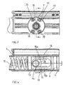
- the operating mechanism proper is designated 2. It includes a frame 3 with a cylinder 4, fig 4, in which one part, as an unit designated 6, is movable in order to turn an axle 7.
- a system of arms 8, 9 (Fig. 1) is connected to the axle 7, of which an outer arm 9 is intended to be connected to the doorleaf whose movement is to be controlled by the unit 1.
- the closing movement is accomplished by a spring 10 partly shown in fig 4 and biassing part 6, whereas the opening movement is accomplished by hydraulic means in that a motor 11, with the help of a pump 12, generates a pressure in the cylinder 4. This pressure, working against the closing spring 10, displaces the piston device on part 6 in the opening direction.
- the piston part 6 is rigidly connected to a part 13 and from this the linear reciprocating movement of part 6 is transferred to the arm system 8, 9 by means of a toothed wheel 14, the axle 7 of which is carried by the frame 3 as described below, by its teeth engaging one row of teeth 15 on the portion 13 of part 6.
- two opposite rows of teeth, 15a and 15b respectively, are arranged on the displaceable part 13 of part 6.
- the axle 7 supporting the toothed wheel 14, the free end of which is intended to be connected to the arm system 8,9, is eccentrically mounted with at the bearing parts 16 cooperating therewith.
- These bearing parts have cylindrical circumferential contact surfaces resting in cylindrical seats arranged in frame 3. This means that the bearing parts with the bearings in which the toothed wheel 14 axle 7 is housed, together with the axle and toothed wheel, can be moved into different turning positions relative to the frame.
- a turning of the said bearing parts 16 means results in a shifting of the rotation axis of the toothed wheel relative to the rows of teeth 15a, 15b. This means that by turning to a first position, the toothed wheel 14 can be made engage the one row of teeth 15a, and by turning to a second position, be made engage the other row of teeth 15b.
- the part 6 including the piston section and part 13 are made as a unit and the latter part has an elongated opening 18 extending in the axial direction. Along the opposing sides of the opening, the teeth 15a and 15b are arranged.
- the bearing parts have protruding flanges 16 that rest against the exterior of the frame 3 and that are furnished with slot-shaped cavities for locking screws 20. By loosening the locking screws 20, the bearing units are freed from the frame 3 and can be turned in one direction or the other and then be re-secured by means of the screws. The eccentricity of the position of the bearing parts is then adjusted so that a shifting or, more correctly, a turning of the bearing parts between their outer or end positions causes a shifting of the bearing parts and the toothed wheel 14 from engaging the row of teeth on the one side to the row of teeth of the other side.
- this arrangement can also be used with apparatuses only function of which is to close doors where the opening causes an accumulation of force in a spring or similar device to utilised to give a driving force for a closing movement suitably controlled in a per se known way by a hydraulic system of control.
- the arrangement can naturally be used for other types of operating mechanisms than hydraulic ones, for example linear motors and the like.
Landscapes
- Power-Operated Mechanisms For Wings (AREA)
- Refrigerator Housings (AREA)
- Wing Frames And Configurations (AREA)
Claims (7)
- Agencement de fonctionnement de dispositifs pour des portes actionnées mécaniquement comprenant un mécanisme d'actionnement (6), un premier et un deuxième dispositif de transmission de forces (13, 14) et un mécanisme de commande (2) agencés dans un châssis (3), où le mécanisme d'actionnement (6) est agencé pour donner au premier dispositif de transmission de forces (13) un mouvement linéaire et ledit premier dispositif de transmission de forces donne à son tour au second dispositif de transmission de forces (14) un mouvement rotatif ou tournant, et où le premier dispositif de transmission de forces (13) présente au moins une portion comportant une roue dentée ou bien une rangée de dents (15a, 15b) dans la direction du mouvement linéaire, tandis que le second dispositif de transmission de forces (14), le long d'au moins d'une partie de sa périphérie, présente des dents qui engrènent avec les dents de la rangée de dents agencée dans la direction du mouvement linéaire, reliée essentiellement d'une manière rigide au mécanisme d'actionnement (6), caractérisé en ce que le premier dispositif de transmission de forces (13) déplaçable dans des directions linéaires, présente deux portions linéaires présentant des dents (15a, 15b), les portions étant opposées l'une à l'autre et se trouvant à une distance l'une de l'autre,
en ce que le dispositif de transmission de forces tournant ou rotatif (14) qui est pourvu de dents, peut tourner autour d'un axe (7) qui est essentiellement parallèle avec et s'étendent entre les plans des deux portions linéaires présentant des dents (15a, 15b) et est installé dans des paliers transversalement mobiles entre lesdits plans,
en ce que le deuxième dispositif de transmission de forces rotatif ou tournant (14) pourvu de dents est localisé entre les portions linéaires (15a, 15b) présentant des dents et possède une extension radiale qui permet une prise d'engrènement avec seulement l'une de ces portions linéaires à la fois, et
en ce qu'un montage mobile (16, 17) permet le déplacement du deuxième dispositif de transmission de forces rotatif ou tournant (14) pourvu de dents vers ou au loin, respectivement des portions linéaires présentant des dents (15a, 15b), de chaque côté de celui-ci pour la mise en ou hors prise avec l'une desdites portions à la fois. - Agencement selon la revendication 1, caractérisé en ce que le deuxième dispositif de transmission de forces tournant pourvu de dents (14) est installé dans un dispositif formant palier (16) qui comporte des surfaces de support circulaires en vue d'une interaction avec un moyen de siège rotatif agencé dans le châssis (3), en ce que l'axe de rotation dudit deuxième dispositif de transmission de forces (14) est agencé d'une manière excentrique relativement à l'axe du dispositif formant palier et en ce que l'agencement excentrique entre l'axe du deuxième dispositif de transmission de forces (14) et l'axe du dispositif formant palier (16) est réglé de façon que la rotation du dispositif formant palier (16) se traduit par un déplacement du deuxième dispositif de transmission de forces (14) vers et au loin des portions linéaires présentant des dents.
- Agencement selon la revendication 1 ou 2, caractérisé en ce qu'un mécanisme de verrouillage (19) agissant conjointement avec le dispositif formant palier (16) est agencé pour maintenir le dispositif formant palier (16) dans une position spécifiée réglée ou, après le relâchement, pour permettre sa rotation vers une autre position.
- Agencement selon la revendication 1 ou 2, caractérisé en ce que le deuxième dispositif de transmission de forces (14) a un diamètre défini de façon que dans une première position de déplacement, il vienne en prise avec l'une des deux portions linéaires présentant des dents (15a) et, dans une deuxième position de déplacement, il vienne en prise avec l'autre des deux portions linéaires présentant des dents (15b), et en ce que l'agencement excentrique des dispositifs est réglé de façon que par la rotation du dispositif formant palier (16), un déplacement du montage de dispositif (17) et ainsi du deuxième dispositif de transmission de forces (14) d'une position à l'autre est atteint.
- Agencement selon la revendication 1, 2 ou 3, caractérisé en ce que le mécanisme de fonctionnement comporte un ressort (10).
- Agencement selon la revendication 1, 2 ou 3, caractérisé en ce que le mécanisme de fonctionnement comporte un agencement à piston et à vérin (6) réagissant à la pression.
- Agencement selon la revendication 1, 2 ou 3, caractérisé en ce que le mécanisme de fonctionnement comporte un ressort (10) pour le déplacement du premier dispositif de transmission de forces dans une direction ainsi qu'un agencement à piston et à vérin réagissant à la pression pour le déplacement dans l'autre direction.
Applications Claiming Priority (2)
| Application Number | Priority Date | Filing Date | Title |
|---|---|---|---|
| SE9702085A SE509527C2 (sv) | 1997-06-02 | 1997-06-02 | Anordning vid manöversystem för kraftdrivna dörrar |
| SE9702085 | 1997-06-02 |
Publications (3)
| Publication Number | Publication Date |
|---|---|
| EP0894932A2 EP0894932A2 (fr) | 1999-02-03 |
| EP0894932A3 EP0894932A3 (fr) | 1999-04-14 |
| EP0894932B1 true EP0894932B1 (fr) | 2003-01-02 |
Family
ID=20407205
Family Applications (1)
| Application Number | Title | Priority Date | Filing Date |
|---|---|---|---|
| EP98850090A Expired - Lifetime EP0894932B1 (fr) | 1997-06-02 | 1998-05-28 | Agencement pour dispositifs de fermeture et/ou d'ouverture de portes |
Country Status (4)
| Country | Link |
|---|---|
| EP (1) | EP0894932B1 (fr) |
| AT (1) | ATE230461T1 (fr) |
| DE (1) | DE69810397T2 (fr) |
| SE (1) | SE509527C2 (fr) |
Families Citing this family (2)
| Publication number | Priority date | Publication date | Assignee | Title |
|---|---|---|---|---|
| US7152718B2 (en) | 2002-04-16 | 2006-12-26 | Illinois Tool Works Inc | Damper |
| DE10325027B4 (de) * | 2003-06-02 | 2007-04-05 | Dorma Gmbh + Co. Kg | Drehtürantrieb für eine mindestens einflügelige Tür |
Family Cites Families (2)
| Publication number | Priority date | Publication date | Assignee | Title |
|---|---|---|---|---|
| US3059268A (en) * | 1959-07-02 | 1962-10-23 | Independent Lock Co | Door closer |
| DE4323150B4 (de) * | 1993-07-10 | 2004-09-23 | Geze Gmbh | Drehtürantrieb |
-
1997
- 1997-06-02 SE SE9702085A patent/SE509527C2/sv not_active IP Right Cessation
-
1998
- 1998-05-28 AT AT98850090T patent/ATE230461T1/de active
- 1998-05-28 DE DE69810397T patent/DE69810397T2/de not_active Expired - Lifetime
- 1998-05-28 EP EP98850090A patent/EP0894932B1/fr not_active Expired - Lifetime
Also Published As
| Publication number | Publication date |
|---|---|
| EP0894932A3 (fr) | 1999-04-14 |
| SE509527C2 (sv) | 1999-02-08 |
| EP0894932A2 (fr) | 1999-02-03 |
| SE9702085L (sv) | 1998-12-03 |
| SE9702085D0 (sv) | 1997-06-02 |
| DE69810397D1 (de) | 2003-02-06 |
| ATE230461T1 (de) | 2003-01-15 |
| DE69810397T2 (de) | 2003-08-21 |
Similar Documents
| Publication | Publication Date | Title |
|---|---|---|
| US7143547B2 (en) | Spring assisted swing door operator | |
| US5480198A (en) | Drive arrangement for a security system | |
| KR970006334B1 (ko) | 가변 토크 세팅 기계 | |
| KR890001668A (ko) | 유성식 트랜스미션 및 위치결정 유니트를 구비한 공구 고정구 터릿 | |
| US4147073A (en) | Garage door opener | |
| EP0894932B1 (fr) | Agencement pour dispositifs de fermeture et/ou d'ouverture de portes | |
| EP0089129B1 (fr) | Mécanisme de transmission de force avec régulateur de jeu pour robot industriel | |
| US20080163772A1 (en) | Register Adjusting Apparatus for Rotating Body | |
| US4922790A (en) | Dynamic phase adjuster | |
| JPH0788913B2 (ja) | バルブのスピンドル駆動機構 | |
| EP0018978A1 (fr) | Appareil de transformation d'un mouvement rotatif en un mouvement lineaire | |
| US5862698A (en) | Bending device | |
| JP2779140B2 (ja) | くわえ胴のくわえ機構の調整装置 | |
| US5158019A (en) | Device for infinitely variable adjustment of the axial spreading movement of distributing rollers | |
| US4955254A (en) | Eccentricity control device | |
| EP0322884B1 (fr) | Dispositif pour le réglage de la course dans une presse | |
| US5823055A (en) | Worm gear drive locking apparatus | |
| US4880949A (en) | Switch drive for a rotary switch | |
| US20070175729A1 (en) | Retractable stop assembly | |
| EP3626926B1 (fr) | Dispositif d'entraînement de porte | |
| US20030123166A1 (en) | Automobile mirror swiveling device | |
| JPH049603Y2 (fr) | ||
| USRE27403E (en) | Variable pitch linear actuator | |
| US9568054B2 (en) | Actuating device | |
| EP0466035A1 (fr) | Régulation de vitre, en particulier pour véhicules automobiles |
Legal Events
| Date | Code | Title | Description |
|---|---|---|---|
| PUAI | Public reference made under article 153(3) epc to a published international application that has entered the european phase |
Free format text: ORIGINAL CODE: 0009012 |
|
| AK | Designated contracting states |
Kind code of ref document: A2 Designated state(s): AT BE DE FR GB IT NL SE |
|
| AX | Request for extension of the european patent |
Free format text: AL;LT;LV;MK;RO;SI |
|
| PUAL | Search report despatched |
Free format text: ORIGINAL CODE: 0009013 |
|
| RHK1 | Main classification (correction) |
Ipc: E05F 3/00 |
|
| AK | Designated contracting states |
Kind code of ref document: A3 Designated state(s): AT BE CH CY DE DK ES FI FR GB GR IE IT LI LU MC NL PT SE |
|
| AX | Request for extension of the european patent |
Free format text: AL;LT;LV;MK;RO;SI |
|
| 17P | Request for examination filed |
Effective date: 19990429 |
|
| AKX | Designation fees paid |
Free format text: AT BE DE FR GB IT NL SE |
|
| 17Q | First examination report despatched |
Effective date: 20011012 |
|
| GRAG | Despatch of communication of intention to grant |
Free format text: ORIGINAL CODE: EPIDOS AGRA |
|
| GRAG | Despatch of communication of intention to grant |
Free format text: ORIGINAL CODE: EPIDOS AGRA |
|
| GRAH | Despatch of communication of intention to grant a patent |
Free format text: ORIGINAL CODE: EPIDOS IGRA |
|
| GRAH | Despatch of communication of intention to grant a patent |
Free format text: ORIGINAL CODE: EPIDOS IGRA |
|
| GRAA | (expected) grant |
Free format text: ORIGINAL CODE: 0009210 |
|
| AK | Designated contracting states |
Kind code of ref document: B1 Designated state(s): AT BE DE FR GB IT NL SE |
|
| REF | Corresponds to: |
Ref document number: 230461 Country of ref document: AT Date of ref document: 20030115 Kind code of ref document: T |
|
| REG | Reference to a national code |
Ref country code: GB Ref legal event code: FG4D Free format text: 20030102 |
|
| REF | Corresponds to: |
Ref document number: 69810397 Country of ref document: DE Date of ref document: 20030206 Kind code of ref document: P |
|
| RAP2 | Party data changed (patent owner data changed or rights of a patent transferred) |
Owner name: BESAM INTERNATIONAL HB |
|
| REG | Reference to a national code |
Ref country code: SE Ref legal event code: TRGR |
|
| NLT2 | Nl: modifications (of names), taken from the european patent patent bulletin |
Owner name: BESAM INTERNATIONAL HB |
|
| ET | Fr: translation filed | ||
| PLBE | No opposition filed within time limit |
Free format text: ORIGINAL CODE: 0009261 |
|
| STAA | Information on the status of an ep patent application or granted ep patent |
Free format text: STATUS: NO OPPOSITION FILED WITHIN TIME LIMIT |
|
| 26N | No opposition filed |
Effective date: 20031003 |
|
| REG | Reference to a national code |
Ref country code: GB Ref legal event code: 732E |
|
| NLS | Nl: assignments of ep-patents |
Owner name: ASSA ABLOY IP AB Effective date: 20070319 |
|
| REG | Reference to a national code |
Ref country code: FR Ref legal event code: TP |
|
| REG | Reference to a national code |
Ref country code: FR Ref legal event code: PLFP Year of fee payment: 19 |
|
| REG | Reference to a national code |
Ref country code: FR Ref legal event code: PLFP Year of fee payment: 20 |
|
| PGFP | Annual fee paid to national office [announced via postgrant information from national office to epo] |
Ref country code: NL Payment date: 20170512 Year of fee payment: 20 |
|
| PGFP | Annual fee paid to national office [announced via postgrant information from national office to epo] |
Ref country code: DE Payment date: 20170523 Year of fee payment: 20 Ref country code: FR Payment date: 20170413 Year of fee payment: 20 Ref country code: GB Payment date: 20170524 Year of fee payment: 20 |
|
| PGFP | Annual fee paid to national office [announced via postgrant information from national office to epo] |
Ref country code: AT Payment date: 20170425 Year of fee payment: 20 Ref country code: BE Payment date: 20170413 Year of fee payment: 20 Ref country code: IT Payment date: 20170522 Year of fee payment: 20 Ref country code: SE Payment date: 20170511 Year of fee payment: 20 |
|
| REG | Reference to a national code |
Ref country code: DE Ref legal event code: R071 Ref document number: 69810397 Country of ref document: DE |
|
| REG | Reference to a national code |
Ref country code: NL Ref legal event code: MK Effective date: 20180527 |
|
| REG | Reference to a national code |
Ref country code: GB Ref legal event code: PE20 Expiry date: 20180527 |
|
| REG | Reference to a national code |
Ref country code: SE Ref legal event code: EUG |
|
| REG | Reference to a national code |
Ref country code: AT Ref legal event code: MK07 Ref document number: 230461 Country of ref document: AT Kind code of ref document: T Effective date: 20180528 |
|
| REG | Reference to a national code |
Ref country code: BE Ref legal event code: MK Effective date: 20180528 |
|
| PG25 | Lapsed in a contracting state [announced via postgrant information from national office to epo] |
Ref country code: GB Free format text: LAPSE BECAUSE OF EXPIRATION OF PROTECTION Effective date: 20180527 |