EP0894957A2 - Direkteinspritzbrennkraftmaschine mit Funkenzündung - Google Patents
Direkteinspritzbrennkraftmaschine mit Funkenzündung Download PDFInfo
- Publication number
- EP0894957A2 EP0894957A2 EP98114014A EP98114014A EP0894957A2 EP 0894957 A2 EP0894957 A2 EP 0894957A2 EP 98114014 A EP98114014 A EP 98114014A EP 98114014 A EP98114014 A EP 98114014A EP 0894957 A2 EP0894957 A2 EP 0894957A2
- Authority
- EP
- European Patent Office
- Prior art keywords
- swirl
- charge combustion
- combustion region
- engine
- intensity
- Prior art date
- Legal status (The legal status is an assumption and is not a legal conclusion. Google has not performed a legal analysis and makes no representation as to the accuracy of the status listed.)
- Granted
Links
Images




Classifications
-
- F—MECHANICAL ENGINEERING; LIGHTING; HEATING; WEAPONS; BLASTING
- F02—COMBUSTION ENGINES; HOT-GAS OR COMBUSTION-PRODUCT ENGINE PLANTS
- F02B—INTERNAL-COMBUSTION PISTON ENGINES; COMBUSTION ENGINES IN GENERAL
- F02B31/00—Modifying induction systems for imparting a rotation to the charge in the cylinder
- F02B31/08—Modifying induction systems for imparting a rotation to the charge in the cylinder having multiple air inlets
- F02B31/085—Modifying induction systems for imparting a rotation to the charge in the cylinder having multiple air inlets having two inlet valves
-
- F—MECHANICAL ENGINEERING; LIGHTING; HEATING; WEAPONS; BLASTING
- F02—COMBUSTION ENGINES; HOT-GAS OR COMBUSTION-PRODUCT ENGINE PLANTS
- F02D—CONTROLLING COMBUSTION ENGINES
- F02D41/00—Electrical control of supply of combustible mixture or its constituents
- F02D41/30—Controlling fuel injection
- F02D41/3011—Controlling fuel injection according to or using specific or several modes of combustion
- F02D41/3064—Controlling fuel injection according to or using specific or several modes of combustion with special control during transition between modes
-
- F—MECHANICAL ENGINEERING; LIGHTING; HEATING; WEAPONS; BLASTING
- F02—COMBUSTION ENGINES; HOT-GAS OR COMBUSTION-PRODUCT ENGINE PLANTS
- F02F—CYLINDERS, PISTONS OR CASINGS, FOR COMBUSTION ENGINES; ARRANGEMENTS OF SEALINGS IN COMBUSTION ENGINES
- F02F1/00—Cylinders; Cylinder heads
- F02F1/24—Cylinder heads
- F02F1/42—Shape or arrangement of intake or exhaust channels in cylinder heads
- F02F1/4214—Shape or arrangement of intake or exhaust channels in cylinder heads specially adapted for four or more valves per cylinder
-
- F—MECHANICAL ENGINEERING; LIGHTING; HEATING; WEAPONS; BLASTING
- F02—COMBUSTION ENGINES; HOT-GAS OR COMBUSTION-PRODUCT ENGINE PLANTS
- F02B—INTERNAL-COMBUSTION PISTON ENGINES; COMBUSTION ENGINES IN GENERAL
- F02B75/00—Other engines
- F02B75/12—Other methods of operation
- F02B2075/125—Direct injection in the combustion chamber for spark ignition engines, i.e. not in pre-combustion chamber
-
- F—MECHANICAL ENGINEERING; LIGHTING; HEATING; WEAPONS; BLASTING
- F02—COMBUSTION ENGINES; HOT-GAS OR COMBUSTION-PRODUCT ENGINE PLANTS
- F02B—INTERNAL-COMBUSTION PISTON ENGINES; COMBUSTION ENGINES IN GENERAL
- F02B2275/00—Other engines, components or details, not provided for in other groups of this subclass
- F02B2275/48—Tumble motion in gas movement in cylinder
-
- F—MECHANICAL ENGINEERING; LIGHTING; HEATING; WEAPONS; BLASTING
- F02—COMBUSTION ENGINES; HOT-GAS OR COMBUSTION-PRODUCT ENGINE PLANTS
- F02D—CONTROLLING COMBUSTION ENGINES
- F02D41/00—Electrical control of supply of combustible mixture or its constituents
- F02D41/0002—Controlling intake air
- F02D2041/0015—Controlling intake air for engines with means for controlling swirl or tumble flow, e.g. by using swirl valves
-
- F—MECHANICAL ENGINEERING; LIGHTING; HEATING; WEAPONS; BLASTING
- F02—COMBUSTION ENGINES; HOT-GAS OR COMBUSTION-PRODUCT ENGINE PLANTS
- F02F—CYLINDERS, PISTONS OR CASINGS, FOR COMBUSTION ENGINES; ARRANGEMENTS OF SEALINGS IN COMBUSTION ENGINES
- F02F1/00—Cylinders; Cylinder heads
- F02F1/24—Cylinder heads
- F02F2001/244—Arrangement of valve stems in cylinder heads
- F02F2001/245—Arrangement of valve stems in cylinder heads the valve stems being orientated at an angle with the cylinder axis
-
- Y—GENERAL TAGGING OF NEW TECHNOLOGICAL DEVELOPMENTS; GENERAL TAGGING OF CROSS-SECTIONAL TECHNOLOGIES SPANNING OVER SEVERAL SECTIONS OF THE IPC; TECHNICAL SUBJECTS COVERED BY FORMER USPC CROSS-REFERENCE ART COLLECTIONS [XRACs] AND DIGESTS
- Y02—TECHNOLOGIES OR APPLICATIONS FOR MITIGATION OR ADAPTATION AGAINST CLIMATE CHANGE
- Y02T—CLIMATE CHANGE MITIGATION TECHNOLOGIES RELATED TO TRANSPORTATION
- Y02T10/00—Road transport of goods or passengers
- Y02T10/10—Internal combustion engine [ICE] based vehicles
- Y02T10/12—Improving ICE efficiencies
Definitions
- This invention relates to improvements in a cylinder direct injection spark-ignition internal combustion engine, and more particularly to a control system for variably controlling the intensity of swirl to be generated in a cylinder of the engine.
- Hitherto cylinder direct injection spark-ignition internal combustion engines have been proposed and put into practical use, in which fuel is directly injected into each cylinder of the engine. Typical one of them is disclosed in Japanese Patent Provisional Publication No. 2-125911.
- This engine is configured as follows: Each piston is formed at its crown with a cavity.
- a spark plug is installed to a cylinder head and located to face the peripheral portion of the cavity.
- a fuel injector is disposed to project in the cylinder so as to directly inject fuel into the cylinder, and located to prevent injected fuel from directly splashing onto the spark plug.
- this engine is provided with a device for controlling the intensity of swirl of air-fuel mixture to be generated in the cylinder.
- the intensity of swirl is increased by the swirl intensity controlling device, while fuel is injected from the fuel injector at the latter half of compression stroke, thereby gathering combustible mixture around the spark plug.
- the combustible mixture is burnt to accomplish stratified charge combustion in the cylinder.
- the intensity of swirl is decreased, while fuel is injected on intake stroke thereby to previously mix fuel and air. This forms homogeneous air-fuel mixture throughout the whole combustion chamber thus to accomplishing homogeneous charge combustion in the cylinder.
- the intensity of swirl is changed in accordance with engine load which is largely changed stepwise, for example, when acceleration and deceleration are abruptly repeated in the stratified charge combustion region. Accordingly, change in swirl (i.e., change in combustion condition) becomes abrupt thereby degrading driveability of the engine. Otherwise, if only the intensity of swirl is gradually changed during sudden acceleration or deceleration in the stratified charge combustion region, there arises the fear that no matching is established between the magnitude of engine load and the magnitude of the swirl intensity.
- engine operation is divided into the stratified charge combustion region and a homogeneous charge combustion region where homogeneous charge combustion is made, in which the homogeneous charge combustion region is further divided into a lean homogeneous charge combustion region and a stoichiometric homogeneous charge combustion region (including a high power output homogeneous charge combustion region).
- the intensity of swirl is gradually decreased in the stratified charge combustion condition, immediately decreased in the lean homogeneous charge combustion region, and again decreased immediately after reaching the stoichiometric homogeneous charge combustion region.
- the intensity of swirl in the cylinder is unavoidably changed largely whenever combustion condition in the cylinder is changed over. Even if the intensity of swirl is changed in accordance with engine load in a process that engine operation is changed from the stratified charge combustion region through the lean homogeneous charge combustion region to the stoichiometric homogeneous charge combustion region under a change in engine load, change in swirl intensity becomes abrupt thereby degrading driveability of the engine.
- Another object of the present invention is to provide an improved cylinder direct injection spark-ignition internal combustion engine, in which combustion condition in each cylinder cannot be abruptly changed even under abrupt acceleration and deceleration of the engine.
- a further object of the present invention is to provide an improved cylinder direct injection spark-ignition internal combustion engine, in which the intensity of swirl to be generated in each cylinder is variably controlled in accordance with engine speed which does not make its abrupt change.
- An aspect of the present invention resides, as shown in Fig. 16, in a cylinder direct injection spark-ignition internal combustion engine which comprises a section 41 for controlling an intensity of swirl to be formed in a cylinder of the engine.
- a section 42 is provided to detect a stratified charge combustion region in accordance with an engine operating condition.
- a section 43 is provided to regulate the swirl intensity controlling section so as to change the intensity of swirl in accordance with an engine speed of the engine, in the stratified charge combustion region detected by the detecting section.
- a cylinder direct injection spark-ignition internal combustion engine which comprises a swirl control valve movably disposed in a passage connected to a cylinder of the engine, the swirl control valve regulating a swirl ratio in the cylinder.
- a sensor is provided to detect an engine operating condition representative of a stratified charge combustion region.
- a controller is provided to control the swirl control valve so as to change the swirl ratio in accordance an engine speed of the engine, in the stratified charge combustion region detected by the sensor.
- the intensity of swirl is changed in accordance with engine speed which hardly makes its abrupt change, without being changed in accordance with engine load which may its abrupt change.
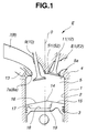
- the engine E of this embodiment is for an automotive vehicle and comprises a cylinder block 1 in which a plurality of engine cylinders 2 are formed though only one engine cylinder 2 is shown.
- a piston 3 is movably disposed in each cylinder.
- a cylinder head 4 is fixed to the top surface of the cylinder block 1.
- a pentrooftype combustion chamber 5 is formed between the piston 3 and the cylinder head 4.
- Two intake ports 7, 8 and two exhaust ports E1 and E2 are formed in the cylinder head 4.
- the intake ports 7, 8 are largely inclined relative to a vertical plane (not shown) containing the axes O of the cylinders 2 in order to prevent the an intake manifold (not shown) to be installed from being located at a high position relative to the engine E.
- the intake port 7, 8 open to the combustion chamber 5 respectively through valve seats 7a, 8a.
- Intake valves 9, 10 are movably disposed to be seatable respectively on the valve seats 7a, 8a.
- exhaust ports E1, E2 open to the combustion chamber 5 respectively through valve seats S1, S2.
- Exhaust valves 11, 12 are movably disposed to be seatable respectively on the valve seats S1, S2.
- a spark plug 6 and a fuel injector 13 are disposed in the cylinder head 4 so as to project into the combustion chamber 5.
- the spark plug 6 is located such that its axis is slightly separate from the axis O of the cylinder 2.
- the tip end section of the fuel injector 13 is located near the periphery of the combustion chamber 5 as shown in Fig. 1 and positioned between the two intake valves 9, 10 as viewed from the upper side as shown in Fig. 2.
- the piston 3 has its roof-type top surface including inclined surfaces 15, 16 which are contiguous through a ridgeline 14.
- a generally dish-shaped circular cavity 17 is formed at the top surface of the piston 3 so as to be eccentric to the side of the fuel injector 13 relative to the axis O of the cylinder 2 as viewed from the upper side. More specifically, the cavity 17 has a flat bottom wall surface 18 which is perpendicular to the axis O of the cylinder 2.
- a generally annular side wall surface 19 extends upward from the periphery of the bottom surface 18 and reaches the top surface of the piston 3. The diameter of the side wall surface 19 increases in a direction toward the top surface of the piston 3.
- the cavity 17 is defined by the bottom wall surface 18 and the side wall surface 19.
- the side wall surface 19 has a predetermined inclination angle relative to the vertical plane containing the axes O of the cylinders 2, on another vertical plane C (in Fig. 2) perpendicular to the above-mentioned vertical plane (containing the axes O) as illustrated in Fig. 1. Additionally, the cavity 17 is formed in a manner to cut out a central section of the ridgeline 14 between the inclined surfaces 15, 16 of the top surface of the piston 3 so that sprayed fuel from the fuel injector 13 can be gathered around the spark plug 6 in an engine operating region where stratified charge combustion is carried out.
- the shape of the piston 3 and the combustion chamber 5 is symmetrical with respect to the vertical plane C including the axes O of the cylinders as shown in Fig. 2.
- the intake ports 7, 8 are formed generally symmetrical with respect to the vertical plane C, in which the intake port 7 has a larger inclination angle relative to the vertical plane C than that of the intake port 8 as viewed from the upper side as illustrated in Fig. 2. Accordingly, intake air is distributed equally into the intake ports 7, 8 and then flows into the cylinder 2 to form intake air stream.
- the intake air stream descends through an inclined wall surface 5a forming part of the ceiling wall of the combustion chamber 5 and through an inner wall surface of the cylinder 2 contiguous with the inclined wall surface 5a, thereby generating so-called tumble stream which turns in the cylinder 2.
- the fuel injector 13 has an axis which can be directed into the cavity 17 and is inclined downward so as to prevent fuel injected or sprayed from the fuel injector 13 from directly striking against the spark plug 6 as shown in Fig. 1.
- the fuel injected from the fuel injector 13 takes a spray cone whose spray angle is set at a value within a predetermined range at which almost whole the sprayed fuel is within the cavity 17 when fuel is injected upon opening of the fuel injector 13 at the latter half period of compression stroke (where the piston 3 ascends) in the engine operating region where stratified charge combustion is carried out.
- fuel injection from the fuel injector 13 is made on intake stroke (where the piston 3 descends).
- fuel injection timings (at which the fuel injector 13 injects fuel) of the engine E is controlled in accordance with combustion conditions such as stratified charge combustion and homogeneous charge combustion.
- a control unit or controller 31 forming part of a control system S is provided to control the fuel injection timings in accordance with the combustion conditions, and to control a spark timing (at which the spark plug 6 makes its spark) and a fuel injection quantity (at which fuel is injected from the fuel injector 13).
- the control unit 31 is supplied with an intake air quantity signal (from an airflow meter 32) representative of quantity of intake air to be supplied to the engine E, a coolant temperature signal (from a coolant temperature sensor 33) representative of temperature of engine coolant, an engine speed signal (from a crank angle sensor 34) representative of engine speed of the engine E, and an accelerator position signal (from an accelerator position sensor 35) representative of an operation amount of an accelerator.
- the control unit 31 is configured to judge as to which combustion condition (i.e., the engine operating region) is required for the current engine operation, in accordance with the intake air quantity signal, the coolant temperature signal, the engine speed signal and the accelerator position signal.
- the control unit 31 is further configured to calculate the fuel injection quantity and the spark timing corresponding to the judged combustion condition, and output control signals representative of the fuel injection quantity and the spark timing to the fuel injector 13 and the spark plug 6.
- the engine operating regions for the respective combustion conditions are set as shown in Fig. 4.
- Each engine operating region is set and detected in accordance with engine speed detected by the crank angle sensor 34 and engine load determined by the intake air quantity detected by the airflow meter 32, the accelerator operation amount detected by the accelerator position sensor 35 and/or the like.
- the stratified charge combustion or engine operating region R1 (where stratified charge combustion is carried out) lies within a low and medium engine speed range extending from a low engine speed to a medium engine speed of the engine and lines within a low and medium engine load range extending from a low engine load to a medium engine load of the engine.
- a homogeneous charge combustion or engine operating region R2, R3 (where stratified charge combustion is carried out) lies within a medium and high engine speed range and within a medium and high engine load range as shown in Fig. 4.
- fuel injected on intake stroke is uniformly mixed with air in the cylinder and thereafter combusted.
- the homogeneous charge combustion region R2, R3 includes a lean homogeneous charge combustion or engine operating region R2 in which engine operation is made in a lean air-fuel ratio range between air-fuel ratios 20 : 1 and 25 : 1, and a stoichiometric homogeneous charge combustion or engine operating region R3 in which engine operation is made in stoichiometric air-fuel ratio range around stoichiometric air-fuel ratio.
- Fuel economy has preference over engine power output in the lean homogeneous charge combustion region, whereas engine power output has preference over fuel economy in the stoichiometric homogeneous charge combustion region.
- the stoichiometric homogeneous charge combustion region R3 includes a high power output homogeneous charge combustion region which resides around the maximum engine speed of the engine.
- engine operation is made at an air-fuel ratio richer than stoichiometric air-fuel ratio.
- a swirl control valve 23 of the butterfly valve type is rotatably disposed in a branch runner 21 of an exhaust manifold, connected to the intake port 7. Another branch runner 22 of the intake manifold is connected to the intake port 8.
- the swirl control valve 23 is driven by an actuator 24 constituted of a step motor, shown in Fig. 3.
- the opening degree of the swirl control valve 23 is decreased to narrow a flow passage area of the branch runner 21, the rate of the quantity of intake air flowing through the branch runner 22 to the cylinder 2 increases relative to the rate of the quantity of intake air flowing through the branch runner 21 into the cylinder 2, thereby generating swirl of air-fuel mixture in the cylinder 2 as indicated by an arrow A in Fig. 2.
- turning streams generated in the cylinder 2 include swirl (component) which turns around the axis of the cylinder 5, and tumble (component) which turns around an axis (not shown) perpendicular to the axis O of the cylinder 2.
- a swirl ratio is set preferably at a value within a range of from 1.5 to 3.0, or a value not less than about 3.
- the swirl ratio is set preferably at a value not less than 1.5 times of a tumble ratio.
- the swirl ratio is the number of rotations of the swirl during a time period in which a crankshaft of the engine E makes its one rotation.
- the tumble ratio is the number of rotations of the tumble during a time period in which the crankshaft makes its one rotation.
- the intensity of the swirl is changed in the stratified charge combustion region, the combustion condition will change so as to largely affect driveability of the engine. Consequently, it is preferable to gradually change the intensity of the swirl in order to omit a changeover shock made during changeover of the combustion conditions.
- the intensity of the swirl is changed in accordance with engine load, and therefore change in intensity of swirl (i.e., change in combustion condition) is frequent and abrupt when abrupt acceleration and deceleration are repeated during stratified charge combustion, thereby degrading driveability of the engine.
- the intensity of the swirl is to be controlled as follows: In a process that engine operation is changed over from the stratified charge combustion region (R1) through the lean homogeneous charge combustion region (R2) to the stoichiometric homogeneous charge combustion region (R3), the intensity of the swirl is gradually decreased in the stratified charge combustion region (R1), immediately increased in the lean homogeneous charge combustion region (R2), and again decreased in the stoichiometric homogeneous charge combustion region (R3).
- the intensity of the swirl is largely changed whenever changeover of the combustion conditions is made.
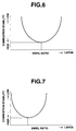
- the intensity of the swirl is controlled to be changeable in accordance with engine speed of the engine E which engine speed is not changed abruptly. More specifically, the opening degree of the swirl control valve 23 is controlled in such a manner as to increase the intensity of the swirl in a low engine speed range and to decrease the intensity of the swirl as the engine speed increases in the stratified charge combustion region R1 as shown in Fig. 5.
- the intensity of swirl is weak and therefore a relatively long time is taken before the air-fuel mixture reaches the spark plug 6 so that no stable combustion can be obtained. Consequently, in the low engine speed range, the intensity of swirl is increased in order to well mix injected fuel with air and to smoothly transport air-fuel mixture to a position around the spark plug 6. Besides, the intensity of swirl increases with an increase in engine speed.
- Fig. 8 the relationship between the swirl ratio and the opening degree of the swirl control valve 23 is shown in Fig. 8. If the characteristics of Fig. 5 is converted into the relationship between the engine speed and the opening degree of the swirl control valve by using the relationship of Fig. 8, a characteristics of Fig. 9 is obtained.
- the control unit 31 When engine operation has come to the stratified charge combustion region, the control unit 31 operates as follows: Searching is made on a table corresponding to Fig. 9 in accordance with the engine speed thereby to determine the opening degree (a target opening degree) of the swirl control valve 23, and then the actuator 24 is driven so that the swirl control valve 23 takes this opening degree.
- the control unit 31 When engine operation is changed over from the stratified charge combustion region R1 to the lean homogeneous charge combustion region R2 along with rise in engine speed in connection with Fig. 4, the control unit 31 operates as follows: The swirl control valve 23 is controlled to take its minimum opening degree (at which the valve 23 is in a generally fully closed state) thereby increasing the intensity of swirl. Then, when engine operation shits to the stoichiometric homogeneous charge combustion region (including the high power output homogeneous charge combustion region) upon a further rise in engine speed, the control unit 31 operates to put the swirl control valve 23 into its fully opened state so as to remove swirl in the cylinder.
- the opening degree of the swirl control valve 23 takes a characteristics shown in Fig. 10, in terms of the engine speed and the opening degree of the swirl control valve 23. This characteristics depicts that the opening degree of the swirl control valve 23 is smaller in the low engine speed range and is increased with rise of engine speed.
- the opening degree of the swirl control valve 23 is controlled in accordance with engine speed which cannot make its abrupt change, without being controlled in accordance with engine load which makes abrupt change.
- combustion condition in the cylinder can be prevented from its abrupt change even though abrupt acceleration and deceleration are repeatedly made in the stratified charge combustion region, thereby suppressing influence on driveability of the engine to a small level.
- the intensity of swirl is increased in the low engine speed range and decreased as engine speed rises. Consequently, combustion in the stratified charge combustion region can be always stable, and therefore good driveability of the engine can be maintained under stable combustion even under abrupt acceleration and deceleration made in the stratified charge combustion region.
- the swirl control valve 23 When engine operation is changed over from the stratified charge combustion region through the lean homogeneous charge combustion region to the stoichiometric homogeneous charge combustion region (including the high power output homogeneous charge combustion region) under the constant engine load, the swirl control valve 23 is changed to its generally fully closed state in the lean homogeneous charge combustion region and to its generally fully opened state in the stoichiometric homogeneous charge combustion region (including the high power output homogeneous charge combustion region) as illustrated in Fig. 10.
- changeover in intensity of swirl in the cylinder is accomplished in accordance with engine speed, among the combustion regions which are largely different in combustion condition, when engine operation is changed over among the combustion regions along with a change in engine speed.
- combustion condition in the cylinder can be prevented from being abruptly changed even when the combustion regions having the respective combustion conditions are changed over with a change in engine speed.
- Figs. 13, 14 and 15 illustrate another embodiment of the engine according to the present invention, similar to the engine of the above embodiment. It will be understood that Figs. 13, 14 and 15 correspond respectively to Figs. 5, 9 and 10 for the above embodiment.
- This embodiment is configured to stepwise change the intensity of swirl in the cylinder in a two-stage manner in which the intensity of swirl is divided into a first stage for the low engine speed range and a second stage for the other engine speed ranges.
- driving manner for the actuator 24 is simplified thereby making it possible to accurately control the actuator 24 without using a precise step motor, thus realizing a low-cost control system for the engine.
Landscapes
- Engineering & Computer Science (AREA)
- Chemical & Material Sciences (AREA)
- Combustion & Propulsion (AREA)
- Mechanical Engineering (AREA)
- General Engineering & Computer Science (AREA)
- Combustion Methods Of Internal-Combustion Engines (AREA)
- Electrical Control Of Air Or Fuel Supplied To Internal-Combustion Engine (AREA)
- Control Of Throttle Valves Provided In The Intake System Or In The Exhaust System (AREA)
- Fuel-Injection Apparatus (AREA)
- Combined Controls Of Internal Combustion Engines (AREA)
Applications Claiming Priority (3)
| Application Number | Priority Date | Filing Date | Title |
|---|---|---|---|
| JP20564097 | 1997-07-31 | ||
| JP205640/97 | 1997-07-31 | ||
| JP20564097A JP3514083B2 (ja) | 1997-07-31 | 1997-07-31 | 筒内直接噴射式火花点火エンジン |
Publications (3)
| Publication Number | Publication Date |
|---|---|
| EP0894957A2 true EP0894957A2 (de) | 1999-02-03 |
| EP0894957A3 EP0894957A3 (de) | 1999-07-21 |
| EP0894957B1 EP0894957B1 (de) | 2003-11-12 |
Family
ID=16510249
Family Applications (1)
| Application Number | Title | Priority Date | Filing Date |
|---|---|---|---|
| EP98114014A Expired - Lifetime EP0894957B1 (de) | 1997-07-31 | 1998-07-27 | Direkteinspritzbrennkraftmaschine mit Funkenzündung |
Country Status (5)
| Country | Link |
|---|---|
| US (1) | US6006718A (de) |
| EP (1) | EP0894957B1 (de) |
| JP (1) | JP3514083B2 (de) |
| KR (1) | KR100306732B1 (de) |
| DE (1) | DE69819620T2 (de) |
Cited By (3)
| Publication number | Priority date | Publication date | Assignee | Title |
|---|---|---|---|---|
| DE10157659B4 (de) * | 2000-12-05 | 2008-06-05 | Ford Global Technologies, LLC (n.d.Ges.d. Staates Delaware), Dearborn | Einlassventil-Zeitsteuerung für nockenlose Mehrventilmotoren |
| WO2015097509A1 (en) * | 2013-12-24 | 2015-07-02 | Toyota Jidosha Kabushiki Kaisha | Control system for spark-ignition internal combustion engine |
| EP3502447A1 (de) * | 2017-12-15 | 2019-06-26 | Mazda Motor Corporation | Steuerungssystem für motor, motor, verfahren zur steuerung eines motors und computerprogrammprodukt |
Families Citing this family (7)
| Publication number | Priority date | Publication date | Assignee | Title |
|---|---|---|---|---|
| JP3903657B2 (ja) * | 1998-12-02 | 2007-04-11 | トヨタ自動車株式会社 | 筒内噴射式火花点火内燃機関 |
| DE102005005324B4 (de) | 2004-02-05 | 2017-03-30 | Denso Corporation | Steuerungsvorrichtung für eine Direkteinspritzbrennkraftmaschine |
| US8662054B2 (en) * | 2011-03-09 | 2014-03-04 | Toyota Jidosha Kabushiki Kaisha | Engine control device |
| JP6176005B2 (ja) * | 2013-09-06 | 2017-08-09 | トヨタ自動車株式会社 | 内燃機関の制御装置 |
| JP6206285B2 (ja) * | 2013-09-06 | 2017-10-04 | トヨタ自動車株式会社 | 内燃機関 |
| KR101887763B1 (ko) * | 2016-10-17 | 2018-09-07 | 현대자동차주식회사 | 차량의 흡기조절장치 |
| JP6627820B2 (ja) * | 2017-04-28 | 2020-01-08 | トヨタ自動車株式会社 | 内燃機関 |
Citations (1)
| Publication number | Priority date | Publication date | Assignee | Title |
|---|---|---|---|---|
| JPH02125911A (ja) | 1988-11-04 | 1990-05-14 | Toyota Motor Corp | 筒内直接噴射内燃機関 |
Family Cites Families (12)
| Publication number | Priority date | Publication date | Assignee | Title |
|---|---|---|---|---|
| JPH0658067B2 (ja) * | 1983-08-09 | 1994-08-03 | マツダ株式会社 | 層状給気エンジン |
| JPS60230529A (ja) * | 1984-04-27 | 1985-11-16 | Mazda Motor Corp | 燃料噴射装置付エンジン |
| EP0235288B1 (de) * | 1985-08-23 | 1992-07-01 | Mitsubishi Jidosha Kogyo Kabushiki Kaisha | Ansaugeanordnung für motoren mit veränderlicher wirbelung |
| US4827883A (en) * | 1988-04-15 | 1989-05-09 | General Motors Corporation | Variable swirl inlet port |
| US5190008A (en) * | 1990-02-15 | 1993-03-02 | Fujitsu Ten Limited | Lean burn internal combustion engine |
| JP2531322B2 (ja) * | 1991-09-13 | 1996-09-04 | トヨタ自動車株式会社 | 内燃機関 |
| JP3221236B2 (ja) * | 1994-06-23 | 2001-10-22 | 株式会社日立製作所 | 内燃機関の制御装置及び制御方法 |
| JP3562016B2 (ja) * | 1994-09-06 | 2004-09-08 | マツダ株式会社 | 自動車用リーンバーンエンジン |
| JPH09273435A (ja) * | 1996-04-05 | 1997-10-21 | Hitachi Ltd | 筒内噴射エンジンの混合気成層化方法およびそれに使用する電子式エンジン制御装置 |
| JP3052869B2 (ja) * | 1996-10-17 | 2000-06-19 | トヨタ自動車株式会社 | 内燃機関の負圧制御装置 |
| JPH10299537A (ja) * | 1997-04-28 | 1998-11-10 | Mazda Motor Corp | 筒内噴射型火花点火式エンジン |
| EP1739294A1 (de) * | 1997-05-20 | 2007-01-03 | Nissan Motor Co., Ltd. | Kolben für eine direkteinspritzende Otto-Brennkraftmaschine |
-
1997
- 1997-07-31 JP JP20564097A patent/JP3514083B2/ja not_active Expired - Lifetime
-
1998
- 1998-07-27 EP EP98114014A patent/EP0894957B1/de not_active Expired - Lifetime
- 1998-07-27 DE DE69819620T patent/DE69819620T2/de not_active Expired - Lifetime
- 1998-07-27 US US09/122,645 patent/US6006718A/en not_active Expired - Lifetime
- 1998-07-30 KR KR1019980030829A patent/KR100306732B1/ko not_active Expired - Lifetime
Patent Citations (1)
| Publication number | Priority date | Publication date | Assignee | Title |
|---|---|---|---|---|
| JPH02125911A (ja) | 1988-11-04 | 1990-05-14 | Toyota Motor Corp | 筒内直接噴射内燃機関 |
Cited By (4)
| Publication number | Priority date | Publication date | Assignee | Title |
|---|---|---|---|---|
| DE10157659B4 (de) * | 2000-12-05 | 2008-06-05 | Ford Global Technologies, LLC (n.d.Ges.d. Staates Delaware), Dearborn | Einlassventil-Zeitsteuerung für nockenlose Mehrventilmotoren |
| WO2015097509A1 (en) * | 2013-12-24 | 2015-07-02 | Toyota Jidosha Kabushiki Kaisha | Control system for spark-ignition internal combustion engine |
| EP3502447A1 (de) * | 2017-12-15 | 2019-06-26 | Mazda Motor Corporation | Steuerungssystem für motor, motor, verfahren zur steuerung eines motors und computerprogrammprodukt |
| US10704480B2 (en) | 2017-12-15 | 2020-07-07 | Mazda Motor Corporation | Control system for compression-ignition engine |
Also Published As
| Publication number | Publication date |
|---|---|
| KR100306732B1 (ko) | 2001-11-15 |
| JPH1150853A (ja) | 1999-02-23 |
| DE69819620T2 (de) | 2004-05-13 |
| EP0894957A3 (de) | 1999-07-21 |
| KR19990014301A (ko) | 1999-02-25 |
| US6006718A (en) | 1999-12-28 |
| EP0894957B1 (de) | 2003-11-12 |
| JP3514083B2 (ja) | 2004-03-31 |
| DE69819620D1 (de) | 2003-12-18 |
Similar Documents
| Publication | Publication Date | Title |
|---|---|---|
| US6173690B1 (en) | In-cylinder direct-injection spark-ignition engine | |
| US6705275B2 (en) | Incylinder direct injection spark ignition engine | |
| US4667636A (en) | Fuel injection type internal combustion engine | |
| US6681739B2 (en) | Control device for direct-injection spark-ignition engine and method of setting fuel injection timing of the same | |
| US4811231A (en) | Apparatus for controlling fuel injection and swirl motion of air in internal combustion engine | |
| US6715463B2 (en) | In-cylinder fuel injection engine and the method of controlling the engine | |
| EP1069291B1 (de) | Direkteinspritzbrennkraftmaschine mit Fremdzündung | |
| US6199534B1 (en) | Control equipment for internal combustion engines | |
| US7168409B2 (en) | Controller for direct injection internal combustion engine | |
| US6006718A (en) | Cylinder direct injection spark-ignition engine | |
| US4658792A (en) | Fuel injection system for internal combustion engine | |
| US20010022169A1 (en) | Control equipment for internal combustion engines | |
| US6691670B1 (en) | Method and engine providing mixing of at least one gaseous fluid such as air and of a fuel in the combustion chamber of a direct-injection internal-combustion engine | |
| JPH04362221A (ja) | 内燃機関の供給燃料制御装置 | |
| JP3671755B2 (ja) | 直噴式内燃機関の吸気制御装置 | |
| JPH04237822A (ja) | 筒内噴射式内燃機関 | |
| JPH06257442A (ja) | ユニフロー式2サイクルエンジン | |
| JP3823612B2 (ja) | 直噴火花点火式内燃機関 | |
| JP3030226B2 (ja) | 自動車用リーンバーンエンジン | |
| JPH0571350A (ja) | 筒内噴射式内燃機関 | |
| JPH068286Y2 (ja) | 2サイクル内燃機関の燃料噴射装置 | |
| JPH04103855A (ja) | 2サイクルエンジンの燃料噴射制御装置 | |
| JPS5941630A (ja) | 火花点火式内燃機関 | |
| JPS6361774A (ja) | エンジンの燃料噴射装置 | |
| JPH06117297A (ja) | 4サイクルエンジンの燃料噴射制御装置 |
Legal Events
| Date | Code | Title | Description |
|---|---|---|---|
| PUAI | Public reference made under article 153(3) epc to a published international application that has entered the european phase |
Free format text: ORIGINAL CODE: 0009012 |
|
| 17P | Request for examination filed |
Effective date: 19980727 |
|
| AK | Designated contracting states |
Kind code of ref document: A2 Designated state(s): DE FR GB |
|
| AX | Request for extension of the european patent |
Free format text: AL;LT;LV;MK;RO;SI |
|
| PUAL | Search report despatched |
Free format text: ORIGINAL CODE: 0009013 |
|
| AK | Designated contracting states |
Kind code of ref document: A3 Designated state(s): AT BE CH CY DE DK ES FI FR GB GR IE IT LI LU MC NL PT SE |
|
| AX | Request for extension of the european patent |
Free format text: AL;LT;LV;MK;RO;SI |
|
| AKX | Designation fees paid |
Free format text: DE FR GB |
|
| 17Q | First examination report despatched |
Effective date: 20011002 |
|
| GRAH | Despatch of communication of intention to grant a patent |
Free format text: ORIGINAL CODE: EPIDOS IGRA |
|
| GRAS | Grant fee paid |
Free format text: ORIGINAL CODE: EPIDOSNIGR3 |
|
| GRAA | (expected) grant |
Free format text: ORIGINAL CODE: 0009210 |
|
| AK | Designated contracting states |
Kind code of ref document: B1 Designated state(s): DE FR GB |
|
| REG | Reference to a national code |
Ref country code: GB Ref legal event code: FG4D |
|
| REF | Corresponds to: |
Ref document number: 69819620 Country of ref document: DE Date of ref document: 20031218 Kind code of ref document: P |
|
| ET | Fr: translation filed | ||
| PLBE | No opposition filed within time limit |
Free format text: ORIGINAL CODE: 0009261 |
|
| STAA | Information on the status of an ep patent application or granted ep patent |
Free format text: STATUS: NO OPPOSITION FILED WITHIN TIME LIMIT |
|
| 26N | No opposition filed |
Effective date: 20040813 |
|
| REG | Reference to a national code |
Ref country code: FR Ref legal event code: PLFP Year of fee payment: 19 |
|
| REG | Reference to a national code |
Ref country code: FR Ref legal event code: PLFP Year of fee payment: 20 |
|
| PGFP | Annual fee paid to national office [announced via postgrant information from national office to epo] |
Ref country code: FR Payment date: 20170613 Year of fee payment: 20 |
|
| PGFP | Annual fee paid to national office [announced via postgrant information from national office to epo] |
Ref country code: GB Payment date: 20170726 Year of fee payment: 20 Ref country code: DE Payment date: 20170719 Year of fee payment: 20 |
|
| REG | Reference to a national code |
Ref country code: DE Ref legal event code: R071 Ref document number: 69819620 Country of ref document: DE |
|
| REG | Reference to a national code |
Ref country code: GB Ref legal event code: PE20 Expiry date: 20180726 |
|
| PG25 | Lapsed in a contracting state [announced via postgrant information from national office to epo] |
Ref country code: GB Free format text: LAPSE BECAUSE OF EXPIRATION OF PROTECTION Effective date: 20180726 |