EP0894985B1 - Echafaudage, notamment pour éléments de meubles, à barres profilées raccordées de manière détachable par un connecteur - Google Patents
Echafaudage, notamment pour éléments de meubles, à barres profilées raccordées de manière détachable par un connecteur Download PDFInfo
- Publication number
- EP0894985B1 EP0894985B1 EP98112266A EP98112266A EP0894985B1 EP 0894985 B1 EP0894985 B1 EP 0894985B1 EP 98112266 A EP98112266 A EP 98112266A EP 98112266 A EP98112266 A EP 98112266A EP 0894985 B1 EP0894985 B1 EP 0894985B1
- Authority
- EP
- European Patent Office
- Prior art keywords
- plate
- coupling
- frame according
- base plate
- connector
- Prior art date
- Legal status (The legal status is an assumption and is not a legal conclusion. Google has not performed a legal analysis and makes no representation as to the accuracy of the status listed.)
- Expired - Lifetime
Links
- 230000008878 coupling Effects 0.000 title claims abstract description 90
- 238000010168 coupling process Methods 0.000 title claims abstract description 90
- 238000005859 coupling reaction Methods 0.000 title claims abstract description 90
- 238000009434 installation Methods 0.000 claims description 4
- 229910000639 Spring steel Inorganic materials 0.000 claims description 3
- 239000013013 elastic material Substances 0.000 claims 1
- 230000002035 prolonged effect Effects 0.000 claims 1
- 238000005452 bending Methods 0.000 description 12
- 230000007480 spreading Effects 0.000 description 8
- 239000002184 metal Substances 0.000 description 7
- 230000009471 action Effects 0.000 description 5
- 230000008859 change Effects 0.000 description 4
- 238000013459 approach Methods 0.000 description 3
- 238000010586 diagram Methods 0.000 description 3
- 206010040954 Skin wrinkling Diseases 0.000 description 2
- 238000006243 chemical reaction Methods 0.000 description 2
- 230000000694 effects Effects 0.000 description 2
- 239000012634 fragment Substances 0.000 description 2
- 239000013067 intermediate product Substances 0.000 description 2
- 229910000831 Steel Inorganic materials 0.000 description 1
- 230000015572 biosynthetic process Effects 0.000 description 1
- 238000010276 construction Methods 0.000 description 1
- 210000003746 feather Anatomy 0.000 description 1
- 238000003780 insertion Methods 0.000 description 1
- 230000037431 insertion Effects 0.000 description 1
- 230000003993 interaction Effects 0.000 description 1
- 238000004519 manufacturing process Methods 0.000 description 1
- 239000000463 material Substances 0.000 description 1
- 230000001151 other effect Effects 0.000 description 1
- 230000009467 reduction Effects 0.000 description 1
- 238000005096 rolling process Methods 0.000 description 1
- 239000010959 steel Substances 0.000 description 1
Images


Classifications
-
- F—MECHANICAL ENGINEERING; LIGHTING; HEATING; WEAPONS; BLASTING
- F16—ENGINEERING ELEMENTS AND UNITS; GENERAL MEASURES FOR PRODUCING AND MAINTAINING EFFECTIVE FUNCTIONING OF MACHINES OR INSTALLATIONS; THERMAL INSULATION IN GENERAL
- F16B—DEVICES FOR FASTENING OR SECURING CONSTRUCTIONAL ELEMENTS OR MACHINE PARTS TOGETHER, e.g. NAILS, BOLTS, CIRCLIPS, CLAMPS, CLIPS OR WEDGES; JOINTS OR JOINTING
- F16B12/00—Jointing of furniture or the like, e.g. hidden from exterior
- F16B12/10—Jointing of furniture or the like, e.g. hidden from exterior using pegs, bolts, tenons, clamps, clips, or the like
- F16B12/12—Jointing of furniture or the like, e.g. hidden from exterior using pegs, bolts, tenons, clamps, clips, or the like for non-metal furniture parts, e.g. made of wood, of plastics
- F16B12/20—Jointing of furniture or the like, e.g. hidden from exterior using pegs, bolts, tenons, clamps, clips, or the like for non-metal furniture parts, e.g. made of wood, of plastics using clamps, clips, wedges, sliding bolts, or the like
-
- F—MECHANICAL ENGINEERING; LIGHTING; HEATING; WEAPONS; BLASTING
- F16—ENGINEERING ELEMENTS AND UNITS; GENERAL MEASURES FOR PRODUCING AND MAINTAINING EFFECTIVE FUNCTIONING OF MACHINES OR INSTALLATIONS; THERMAL INSULATION IN GENERAL
- F16B—DEVICES FOR FASTENING OR SECURING CONSTRUCTIONAL ELEMENTS OR MACHINE PARTS TOGETHER, e.g. NAILS, BOLTS, CIRCLIPS, CLAMPS, CLIPS OR WEDGES; JOINTS OR JOINTING
- F16B7/00—Connections of rods or tubes, e.g. of non-circular section, mutually, including resilient connections
- F16B7/04—Clamping or clipping connections
- F16B7/044—Clamping or clipping connections for rods or tubes being in angled relationship
- F16B7/0446—Clamping or clipping connections for rods or tubes being in angled relationship for tubes using the innerside thereof
- F16B7/0473—Clamping or clipping connections for rods or tubes being in angled relationship for tubes using the innerside thereof with hook-like parts gripping, e.g. by expanding, behind the flanges of a profile
Definitions
- the invention relates to a frame with a connector for each other detachable profile bars, at least some of which are undercut Grooves and others have an end cavity for receiving the connector exhibit.
- the connector consists of at least two profiled plates, which are pushed apart by a spring force, but can be moved against each other by rotating a pressure member.
- there the one plate is provided with a hook end that has at least one Coupling hook that comes from the front when the connector is installed the profile rod protrudes to couple into the groove of the other profile rod protrudes and engages behind the groove wall in the event of a coupling.
- This plate should therefore be called “clutch plate” below.
- the other plate becomes stationary in the cavity of the profile rod in case of assembly positioned. Therefore, this plate should be called the "base plate”.
- the connector In the known frame of this type (DE 16 50 975 A, Fig. 1) the connector consists of two coupling plates arranged in mirror image to each other with coupling hooks pointing away from each other and two on opposite inner surfaces of the cavity by a toothing stationary base plates.
- One is used as a pressure member Grub screw that can be screwed into a threaded hole in one coupling plate is and is supported at the end on the other clutch plate.
- the two hook ends are separated by screwing in the setscrew spread and drive behind the groove on both sides of the coupling lying groove walls of the other profile bar. Except for the one from Pressure element generated spreading movement of the two clutch plates comes there is also an indirect longitudinal movement of the two clutch plates compared to the base plates.
- the two coupling plates Removed from the pressure member's point of application the two coupling plates have contact points for one on the two Base plates each provided sloping surfaces.
- the sloping surfaces are created through mirror-image bends of the base plates, which result in openings engage the associated two hook plates.
- the inside ends of the two Coupling plates form a swivel joint during the spreading movement.
- screwing in of the grub screw slide the provided in the plate openings Contact points along the sloping surfaces. This will make the two mirror-image coupling hooks in the coupling case against the associated Groove walls of the other profile bar used.
- a disadvantage of this known connector is the indispensable double the effort on two coupling plates and two base plates.
- a Reduction of components to just one coupling and one base plate with a transversely movable pressure member, which is both a longitudinal and even a transverse movement of the clutch plate controls seemed impossible.
- Another major disadvantage is the soft, relative movement mutually permissible connection between the two coupled profile bars and the lack of fixation of the two coupling plates in the cavity with uncoupled profile bars.
- the two coupling rods are namely by two leaf springs arranged in mirror image to each other pressed against each other, which are supported on the two base plates.
- the two leaf springs press the clutch plates against each other, justify a lateral play compared to the two base plates, whereby the position of the two coupling hooks in the direction of expansion remains unfixed. Neither in the uncoupling case nor in the coupling case the lateral play between the clutch plates and base plates remove. Because the grub screw engages with the one coupling plate is standing and the coupling plates are screwed in when the grub screw is screwed in to move longitudinally, there must be sufficient longitudinal play between the grub screw and an opening provided in the profile rod for access of the actuation end from the pin.
- the base plate of this connector consists of a U-shaped housing that holds a pivot pin for a pivotal movement of the Coupling plate carries.
- This connector is a simple expansion clamp, where the hook end on the one hand and lugs on the base housing on the other Support at opposite reveal points of the groove of the other profile. The two profile rods are not against each other in the coupling case pressed because there is no longitudinal movement of the clutch plate.
- the invention has for its object a reliable connector with compared to a base plate both longitudinally and transversely movable Coupling plate of the type mentioned at the beginning (DE 16 50 975 A) to develop the coupling for a reliable, firm connection of the two profile bars ensures, easier to manufacture and space-saving is and still by a simple transverse movable pressure member, like a screw.
- This is according to the invention by the Measures listed in the characterizing part of claim 1 are achieved has the following special meaning.
- the first effect is that of the state of the art in this context known longitudinal movement of the clutch plate in the sense of a tightening movement of the coupling hook. In the invention this takes place in a special way.
- the pressure member presses the two Panels directly together and over the inclined surface on the one hand and its associated contact point, on the other hand, becomes the plate longitudinal movement generated.
- the other effect is a swiveling movement of the hook end, which in the invention by a longitudinally offset, in opposite directions to the inclined surface oriented inclination surface on the one hand and an associated contact point on the other hand is obtained between the two plates.
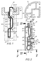
- a fragment of a frame 10 is shown, where two profile bars 11, 12 are held together by means of a special connector 20.
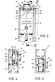
- 6 shows the coupling state of the connector 20 while in Fig. 2 shows the decoupling state, where the two profile bars 11, 12 are separated from each other.
- Fig. 8 includes the connector two self-profiled plates 21, 22, the present Case are integrally formed and a two-legged unit 23 form.
- the connector 20 comprises, apart from this assembly 23, only a pressure member 30, which in the first embodiment shown in FIG. 2 to 9 consists of a simple screw.
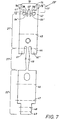
- the assembly 23 is shown in a flat state in FIG. 7
- Produced sheet metal blank 23 ' which consists of spring steel.
- the one there with 21 ', 22 'marked band sections produce dash-dotted lines in Fig. 7 indicated crease and / or bend and / or fold lines 40th to 49, the shape of the unit 23 shown in FIG. 8 7, a narrow intermediate section runs in both band sections 21 ', 22' of FIG 27 ', which is a bow-shaped after a bend on line 45
- Spring 27 is produced on the inner plate ends 28, 29 according to FIG. 9.
- the Spring 27 not only ensures a captive connection between the two plates 21, 22 of the structural unit, but also produces one between the two plates 21 in the spreading force acting when the two plates 21, 22 from the spread position in FIG. 8 into a From Fig. 2 apparent contact position transferred.
- the spring force generated here 16 is marked by an arrow in FIG. 2 and results when the assembly 23 from FIG. 8 in the profile rod 12 according to FIG. 2 mounted.
- This assembly 23 is in one of the front end 14 of the profile rod 12th inserted from accessible cavity 13 and in its inserted position the screw 30 fixed.
- the screw 30 comprises a screw head 31 with a cylindrical outer surface, which is in a hollow cylindrical transverse bore 15 is performed.
- a plate 22 has an opening 24, which extends through the threaded shaft 32 of the screw 30 freely.
- the Screw head 31 acts like a collar to the shaft 32, which is with supports the inside of its collar 33 on the outside 26 of this plate 22.
- the other plate 21 has a threaded bore 25 for the threaded shaft 32, whereby the screw 30 when it is rotated by the arrow 34 in FIG. 2 illustrated rotary actuator can be screwed.
- the two plates 21, 22 are pressed together, which is illustrated in the diagram of FIG. 1 by a push actuation arrow 50 is.
- the two plates 21, 22 perform different functions by what suitable bends, folds in the sheet metal blank 23 'is achieved.
- this coupling hook 36 protrudes from the front end 14 of the profile rod 12 out.
- the coupling hook 36 has a height 37 that is less than / equal to the clear width 17 in the other profile rod to be connected 11 provided groove 18 is.
- This groove 18 of the other profile bar 11 is undercut and has groove walls pointing into the interior of the groove 19. Because of its coupling function at the hook end 35, this plate should 22 hereinafter referred to as "clutch plate”, as already emphasized at the beginning has been.
- this plate 21 becomes stationary in the cavity 13 of the profile rod 12 fixed. Therefore, this plate 21 can be called “base plate” as has already been mentioned at the beginning. This is done through the head 31 of the Screw 30 which is rotatably mounted in the transverse bore 15 in the case of assembly and the plate 21 is fixed by thread engagement in the threaded bore 25.
- this plate has 21 supports 61 to 63, of which, as can be seen 8 and 9, three pieces are provided for a stable three-point system this plate 21 on the inner surfaces of the cavity 13 of the Serve profile bar 12. These supports 61 to 63 are on the inside End 29 and at the outer end 39 of this base plate 21. They are each illustrated by angling from those with 61 ', 62' and 63 'in Fig.
- the inclined surface 56 is on the clutch plate 22 and is there by a suitable cranking of the section shown in FIG. 7 22 'generated in the area of line 46.
- the inclined surface 56 by a Z-shaped bend in the course of the plate the clutch plate 22 generated.
- the inclined surface 56 extends at a negative angle 58, which is caused by bending the plate clockwise.
- the investment site 57 is in the present case by an analog cranking of the Base plate 21 generated, so that one here also from a casserole two Sloping surfaces could speak.
- the inclination surface 66 is opposite to the one described above Inclination surface 56 inclined.
- the one that determines the inclination surface 66 The plate section, seen in the side view of FIG. 8, has a S-curve; with respect to the already mentioned middle level 59, the Inclination surface 66 is a counterclockwise positive Angle 68 on.
- This direction of action 52 is the direction of their cause 50, namely the pressure actuation by the screw is directed in the opposite direction.
- Action 50 is therefore in the opposite direction reaction 52 of swinging out.
- the print direction is 50 between the two plates 21, 22 perpendicular to the train movement 51 of the clutch plate 22.
- action 50 turns two into one another vertical reactions 51, 52 produces, namely a pivoting 51st in the spreading direction and a longitudinal movement 51 in the pulling direction.
- the connector 20 allows an exact adjustment of the desired one 6 apparent pivoting angle 72 of its spreading movement 52
- the position of the contact point 67 is opposite the inclination surface 66 changeable. It’s easier than having that 8 change the inclination angle 68 described above would what is possible in itself.
- the position of the contact point 67 can be increased by curving up or bend fingers 64 change.
- the direction of curvature of the fingers 64 on the base plate 21 is from the hook end 36 of the coupling plate 22 directed away.
- the screw head 31 axially moved in the hollow cylindrical transverse bore 15 of the profile rod 12, like a comparison between the unscrewing position of screw 30 2 with the screw-in position of the screw 30 shows in the coupling state of FIG. 6.
- This axial movement is in 6 is illustrated by an arrow 60.
- the screw head 31 as can be seen from FIG. 6, a head height 73 which is greater than the difference in distance between the plate spacing 54 in the uncoupling state of Fig. 2 and the minimum distance 54 in the coupling state of Fig. 6 is. 6, the screw head 31 should be as possible be flush with the outer surface of the profile rod 12. In the uncoupled state 2 but the screw head 31 must already with his engage the inner end piece in the transverse bore 15 and thereby the already Above mentioned position of the assembled connector 20 in the profile rod Secure 12.
- the base plate 21 has two outer Plate extensions 77, which in the assembly case from the end face 14 of the Project the profile rod 12 and to the side, next to the coupling hook 36 the clutch plate 20 come to rest.
- These plate extensions As shown in the coupling state of FIG. 6, 77 protrude when connected into the groove 18 of the other profile rod 11 and are supported the opposite with respect to the previously described spreading movement 52 Reveal side of the groove 18. This will twist the two interconnected profile bars 11, 12 prevented.
- Im relaxed Condition, d. that is, when the coupling hook is in its uncoupling position 36 according to FIGS. 2 and 4, the coupling hook is in a vertical position Alignment with the two plate extensions 77.
- the plate extensions 77 are aligned with the coupling hook 36 and should have a matching overall width 37 as shown in FIG. 2 exhibit. This is possible because the two plate extensions 77, 3, include between them a fork space, in which the hook end fits with its coupling hook 36. Such a Fork space 79 can also be seen from the flat sheet metal blank 23 'of FIG. 7, that occurs between two band edge extensions 77 ', which is a special outline profile to be described in more detail from attachment parts 75 'and end portions 78.
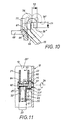
- the band edge extensions 77 'of Fig. 7 initially have two against each other pointing flat tabs 74 along the fold lines there 40 are angled against the coupling plate 22 of the assembly 23, whereby lateral lugs 75 are formed there next to the coupling hooks 36. This can be seen particularly well from FIG. 4. Prevent the approaches 75 a lateral evasive movement of the hook end in the direction of the groove. This results in a guidance for that which can also be seen from FIG. 10 End of hook 36 if the coupling hook over the route 71 and pivoting distance 72 between the release position 36 in the uncoupling state and the engagement position 36 "in the coupling state. In FIG. 10 the starting position 36 'of the coupling hook is also dash-dotted in the dismantled state the assembly 23 shown in FIG. 8.
- the plate extension 77 has, as is apparent from Fig. 9, one Base plate 21 on both sides laterally projecting lugs 76 which - in the case of assembly of the connector in the profile rod 12 according to FIG. 3 - at the front end 14 support and thereby the installation depth of the connector 20 in the cavity Set 13.
- the threaded bore 25 with the side Cross bore 15 aligned in the wall of the profile rod 12 and allowed a quick insertion and screwing in of the screw 30.
- the lugs 76 come through a U-shaped refolding of end portions 78 of the strip edge extensions 77 'of the sheet metal blank 23' shown in FIG. 7 conditions. 7 is the position of the fold lines 41 relevant therefor Refolding indicated.
- FIG. 11 a modified one is used Connector 20 'used.
- the connector 20 ' also has two in the expansion direction according to the force arrow 16 in Fig. 11 spring-loaded plates 21, 22, which act as a base and coupling plate act.
- a pressure member 30 ' is used, the However, shaft 32 'is thread-free and with its inner shaft end 82 is rotatably anchored in the base plate 21.
- the outer shaft end 81 of the pressure member 30 ' analogous to the screw head 31 described above, fixed in the transverse bore 15 of the profile rod 12. But there are the following Deviations of this connector 20 'before.
- the thread-free shaft 32 passes through a hole 25' of the base plate 21 ' and is rotatable 34, but anchored axially. An end flange is used for this 82 at the inside of the shaft.
- the pressure member 30 ' is also supported with a Collar 31 'on the outside 26 of the clutch plate 22, but has on its inside 33 'a wedge surface 83, which 31 this collar converted into a rotary wedge 80. Has in the area of the wedge surface 83 the coupling plate 22 there is an angled section 84 which the wedge surface 83 is supported. With a rotary operation 34 um 180 °, the rotary wedge 80 comes into an opposite rotational position, where the Wedge surface 83, clutch plate 22 in the direction of arrows 50 of FIG.
- the connector 20 'of Fig. 11 is characterized by a particularly simple Assembly in the interior of the cavity 13 of the profile rod 12.
- the connector 20 ' can completely from its components outside the profile rod 12 be pre-assembled.
- the two-legged assembly 23 here as well can already be equipped with the pressure member 30 'from the manufacturer and are delivered in a complete combination of components 23, 30 '.
- the two plates 21, 22 are first compressed so far that the connector 20 'with the fully assembled Pressure member 30 'inserted axially through the profile opening of the rod 12 can be.
- the installation depth in the cavity 13 can also here by the lugs on the base plate already described in the first exemplary embodiment be determined to strike the end of this profile rod 12.
- the Mounting depth is also determined by the fact that the axially inserted Connector 20 with its actuating end 81 in the transverse bore 15 snaps. If you release the compressed plates 21, 22, then the actuating end 81 of the pressure member 30 'by the spring force 16 after Type of a push button pressed into the transverse bore 15. The connector 20 is held in its defined mounting position in the profile rod 12.
Landscapes
- Engineering & Computer Science (AREA)
- General Engineering & Computer Science (AREA)
- Mechanical Engineering (AREA)
- Clamps And Clips (AREA)
- Supports Or Holders For Household Use (AREA)
- Holders For Apparel And Elements Relating To Apparel (AREA)
- Closing And Opening Devices For Wings, And Checks For Wings (AREA)
- Mutual Connection Of Rods And Tubes (AREA)
- Connection Of Plates (AREA)
- Control Of Positive-Displacement Air Blowers (AREA)
- Furniture Connections (AREA)
Claims (24)
- Echaufadage (10), en particulier pour meuble, formé de barres profilées (11, 12), susceptibles d'être accouplées ensemble de façon désolidarisable à l'aide d'un connecteur (20, 20'), barres profilées dont au moins quelques unes présentent des rainures (18) à contre-dépouille, et d'autres présentent un espace creux (13) frontal pour recevoir le connecteur,
et le connecteur (20, 20') est formé d'au moins deux plaques (21, 22) profilées, placées l'une à côté de l'autre,
qui, précisément, sont poussées à l'écart l'une de l'autre à l'aide d'une force élastique (16), mais sont déplaçables l'une vers l'autre (50), avec diminution de leur espacement, par un actionnement en rotation (34) d'un organe de pressage (30, 30'), déplaçable transversalement par rapport à l'orientation des plaques (21, 22) profilées, l'organe de pressage (30, 30') agissant sur un point (55) défini sur l'une des plaques (21, 22),
où une première plaque, précisément une plaque d'accouplement (22), comporte une extrémité formant crochet (35) avec au moins un crochet d'accouplement (36), qui ressort de l'extrémité frontale (14) de la barre profilée (12) lorsque le connecteur (20, 20') est monté, et qui, pour assurer l'accouplement, s'engage dans la rainure (18) de l'autre barre profilée (11) et la saisit par l'arrière,
tandis que l'autre plaque, précisément une plaque de base (21), en cas de montage est placée de façon localement fixe dans l'espace creux (13) de la barre profilée (12),
caractérisé en ce que
les deux plaques (21, 22) présentent entre elles deux paires de profils de commande (56, 57; 66, 67), coopérant chaque fois, ayant leur direction longitudinale espacée l'une de l'autre,
les paires de profils de commande, lors de l'actionnement en rotation (34) de l'organe de pressage (30, 30'), provoquant deux déplacements (51, 52), différents l'un de l'autre de la plaque d'accouplement (22) par rapport à la plaque de base (21), précisémentun déplacement longitudinal (51) de la plaque d'accouplement (22) par rapport à la plaque de base (21), ayant comme effet de tirer le crochet d'accouplement (36) contre l'extrémité frontale (14) de la barre profilée (12), déplacement longitudinal provoqué par la première paire de profils de commande (56, 57) en cas d'actionnement en rotation (34) de l'organe de pressage (30, 30') dans le sens du rapprochement des plaques (50), la première paire de profils de commande (56, 57) étant formée de la face oblique (56), disposée à proximité sur le point d'action (55) de l'organe de pressage (30, 30'), sur une plaque (22), et du point d'application (57) afférent sur l'autre plaque (21), etun déplacement transversal (52) de l'extrémité de crochet (35) de la plaque d'accouplement (22) par rapport à la plaque de base (21), ayant comme effet de faire pivoter le crochet d'accouplement (36) à l'encontre du sens d'approche des plaques (50), derrière la paroi de rainure (19), déplacement transversal qui - en cas d'accouplement des deux barres profilées (11, 12)- lors d'un actionnement en rotation (34) de l'organe de pressage (30, 30') dans le sens d'approche des plaques (50), est provoqué par la deuxième paire de profils de commande (66, 67), qui est formée de la face inclinée (66), inclinée en sens inverse par rapport à la face oblique (56), disposée à distance (65) du point d'action (55) de l'organe de pressage (30 ; 30'), sur une première plaque (22), et d'une zone de contact (67) afférente sur l'autre plaque (21). - Echafaudage selon la revendication 1, caractérisé en ce que l'organe de pressage (30, 30'), présentant une tige (32, 32') et une collerette (31, 31'), est ancré, avec possibilité de rotation par sa tige (32, 32'), précisément dans la plaque de base (21), mais traverse librement (24) la plaque d'accouplement (22),
en ce que l'extrémité de tige (31, 81) extérieure est montée à rotation dans un perçage transversal (15) de la barre profilée (12) et fixe la position de la plaque de base (21) dans l'espace creux (13) de la barre profilée (12)
et en ce que la collerette (31, 31') prend appui sur la face extérieure (26) de la barre d'accouplement (22). - Echafaudage selon la revendication 1 ou 2, caractérisé en ce que l'organe de pressage est formé d'une vis (30) avec une tige filetée (32) et une tête de vis (31) épaissie,
la tige filetée (32) s'engage dans un taraudage (25) de la plaque de base (21) et est susceptible d'y être vissée lors de l'actionnement en rotation (34),
et en ce que la tête de vis (31) prend appui sur la face extérieure (26) de la plaque d'accouplement (22). - Echafaudage selon la revendication 1 ou 2, caractérisé en ce que l'organe de pressage (30') présente une tige (32') exempte de filetage, munie d'une collerette (31'),
dont l'extrémité intérieure de tige (82) est ancrée sur la plaque de base (21), d'une manière permettant une rotation (34) mais axialement stationnaire,
en ce que la collerette (31') est conformée en coin rotatif (80) et présente, sur sa face intérieure de collerette (31'), une face de coin (83) du genre d'une hélicoïde qui prend appui sur un tronçon, coudé (tronçon coudé 84) de la plaque d'accouplement (22),
et en ce que l'extrémité extérieure (81) de la tige (32') s'encliquette au moyen de la charge exercée par une force élastique (16) agissant entre les deux plaques (21, 22), à la façon d'un bouton pression, dans le perçage transversal (15) de la barre profilée (12), lors du montage du connecteur (20'). - Echafaudage selon les revendications 1 à 4, caractérisé en ce que la plaque d'accouplement (22) et la plaque de base (21) forment ensemble une seule pièce.
- Echafaudage selon la revendication 5, caractérisé en ce qu'un ressort (27), qui charge élastiquement (16) les deux plaques (21, 22) dans le sens de l'ouverture par écartement l'une de l'autre, s'étend entre ces deux plaques.
- Echafaudage selon la revendication 5 ou 6, caractérisé en ce que les deux plaques (21, 22) sont formées d'un matériau élastique, tel que de l'acier à ressort, et sont reliées ensemble à leurs extrémités de plaque (28, 29) intérieures au moyen d'un ressort (27) en forme d'étrier, et forment un ensemble de construction (23) à deux branches pour le connecteur (20).
- Echafaudage selon l'une ou plusieurs des revendications 1 à 7, caractérisé en ce que la plaque de base (21) présente des appuis (61, 62, 63) s'étendant transversalement par rapport à la direction de la plaque et prenant appui sur la face intérieure de l'espace creux.
- Echafaudage selon la revendication 8, caractérisé en ce que les appuis (61, 62, 63) sont formés de parties de plaques (61', 62', 63') coudées, se trouvant de préférence sur l'extrémité de plaque (29, 39) extérieure et intérieure de la plaque de base (21).
- Echafaudage selon la revendication 8 ou 9, caractérisé en ce que trois appuis (61, 62, 63) produisent un appui à trois points de la plaque de base (21) sur la face intérieure de l'espace creux.
- Echafaudage selon la revendication 10, caractérisé en ce que les trois appuis sont formés d'un appui extérieur (63) et de deux appuis intérieurs (61, 62),
dont l'appui extérieur (63) est disposé dans la zone médiane de la zone de contact (67) ou de la face inclinée (66),
tandis que les deux appuis intérieurs (61, 62) sont disposés des deux côtés du ressort (27) en forme d'étrier, situé côté extrémité. - Echafaudage selon l'une ou plusieurs de revendications 1 à 11, caractérisé en ce que la tête (31), montée à rotation dans le perçage transversal (15) de la barre profilée (12), de la vis de pressage (30) a une hauteur de tête (73) supérieure/égale à la course maximale de déplacement de rabattement (50) de la plaque d'accouplement (22) par rapport à la plaque de base (21), entre la pleine position de libération et la pleine position d'engagement de l'extrémité formant crochet (35).
- Echafaudage selon l'une ou plusieurs des revendications 1 à 12, caractérisé en ce que la plaque de base (21) présente au moins un prolongement extérieur de plaque (77) qui, en cas de montage du connecteur (20), ressort de la face frontale (14) de la barre profilée (12) et vient se placer latéralement à côté du crochet d'accouplement (36) de la plaque d'accouplement (22),
et en ce que le prolongement de plaque (77), en cas d'accouplement, pénètre dans la rainure (18) de l'autre barre profilée (11). - Echafaudage selon la revendication 13, caractérisé en ce que l'extrémité de plaque (77') extérieure de la plaque de base (21) est fourchue et la bifurcation (79) produit deux prolongements de plaque (77'), conformés l'un par rapport à l'autre en répondant à une symétrie spéculaire,
et en ce que - lorsque le connecteur (20) est monté - l'extrémité formant crochet (35) de la plaque d'accouplement (22) est disposée dans l'espace de fourche (79). - Echafaudage selon la revendication 13 ou 14, caractérisé en ce que le prolongement de plaque (77) de la plaque de base présente un appendice (75) latéral, qui empêche tout déplacement d'échappement de l'extrémité formant crochet (35) dans la direction de la rainure de l'autre barre profilée (11).
- Echafaudage selon la revendication 15, caractérisé en ce que l'appendice (75) est produit par une languette (74) coudée, formée d'un seul tenant sur le prolongement de plaque (77).
- Echafaudage selon l'une ou plusieurs des revendications 13 à 16, caractérisé en ce que le prolongement de plaque (77) porte un ergot (76) qui ressort latéralement de la plaque de base (21) et - lorsque le connecteur (20) est monté - prend appui sur l'extrémité frontale (14) de la barre profilée (12) et détermine la profondeur d'insertion du connecteur (20) dans l'espace creux (13).
- Echafaudage selon la revendication 17, caractérisé en ce que l'ergot (76) est formé par un repli en U d'un tronçon d'extrémité (78) du prolongement de plaque (77).
- Echafaudage selon l'une ou plusieurs des revendications 1 à 18, caractérisé en ce que l'angle d'inclinaison (68) de la face inclinée (66) se trouvant à l'extrémité formant crochet (35) de la plaque d'accouplement (22) et/ou la position de l'emplacement de contact (67) afférent, sur l'extrémité extérieure (39) de la plaque de base (21), sont ajustables.
- Echafaudage selon la revendication 19, caractérisé en ce que la zone de contact (67) est produit par une extrémité extérieure incurvée (extrémité courbée 39) de la plaque de base (21), dont l'arc d'incurvation (69) est modifiable (70) dans le but d'ajuster la position de la zone de contact (67).
- Echafaudage selon la revendication 20, caractérisé en ce que l'extrémité d'incurvation (39) de la plaque de base (21) est munie d'une fente longitudinale (38) et produit plusieurs doigts (63, 64), situés les uns à côté des autres, dont au moins quelques uns d'entre eux (64) forment la zone de contact (67).
- Echafaudage selon la revendication 21, caractérisé en ce que la direction d'incurvation (69) des doigts (64) sur la plaque de base (21) s'écarte de l'extrémité formant crochet (35) de la plaque d'accouplement (21).
- Echafaudage selon la revendication 21 ou 22, caractérisé en ce qu'un doigt (63) est prolongé et forme en même temps l'appui extérieur de la plaque de base (21) qui prend appui - lorsque le connecteur (20) est monté - sur la face intérieure d'espace creux de la barre profilée (12).
- Echafaudage selon l'une ou plusieurs des revendications 1 à 23, caractérisé en ce que la tête de vis (31) présente une face d'enveloppe cylindrique, guidée dans le perçage transversal (15) cylindrique creux de la barre profilée (12) et déplaçable axialement lors de la rotation (34) de la vis de pressage (30).
Applications Claiming Priority (2)
| Application Number | Priority Date | Filing Date | Title |
|---|---|---|---|
| DE19733023A DE19733023C1 (de) | 1997-07-31 | 1997-07-31 | Gestell, insbesondere für Möbel, aus lösbar durch einen Verbinder miteinander kuppelbaren Profilstangen |
| DE19733023 | 1997-07-31 |
Publications (2)
| Publication Number | Publication Date |
|---|---|
| EP0894985A1 EP0894985A1 (fr) | 1999-02-03 |
| EP0894985B1 true EP0894985B1 (fr) | 2002-10-02 |
Family
ID=7837505
Family Applications (1)
| Application Number | Title | Priority Date | Filing Date |
|---|---|---|---|
| EP98112266A Expired - Lifetime EP0894985B1 (fr) | 1997-07-31 | 1998-07-02 | Echafaudage, notamment pour éléments de meubles, à barres profilées raccordées de manière détachable par un connecteur |
Country Status (8)
| Country | Link |
|---|---|
| EP (1) | EP0894985B1 (fr) |
| AT (1) | ATE225466T1 (fr) |
| CZ (1) | CZ232598A3 (fr) |
| DE (2) | DE19733023C1 (fr) |
| DK (1) | DK0894985T3 (fr) |
| ES (1) | ES2180098T3 (fr) |
| PL (1) | PL327766A1 (fr) |
| PT (1) | PT894985E (fr) |
Families Citing this family (3)
| Publication number | Priority date | Publication date | Assignee | Title |
|---|---|---|---|---|
| DE10349534A1 (de) * | 2003-10-22 | 2005-06-16 | Versatile Systems Gmbh | Verbindungselement für Möbelelemente, Möbelelement und Möbelsystem, insbesondere Regalsystem |
| DE102014104413A1 (de) | 2014-03-28 | 2015-10-01 | Hestex Systems B.V. | Verbinder |
| TWI720844B (zh) * | 2020-03-16 | 2021-03-01 | 林永泰 | 隔板的快速接頭 |
Family Cites Families (15)
| Publication number | Priority date | Publication date | Assignee | Title |
|---|---|---|---|---|
| DE1650975A1 (de) * | 1968-01-26 | 1970-10-22 | Johannes Jankowski | Vorrichtung zum Anschliessen bzw. Verbinden von Bauelementen |
| DE7341203U (de) * | 1973-11-17 | 1975-06-26 | Gebr Vieler Gmbh | Gestell mit lösbar verbindbaren Stangenelementen |
| DE2732910A1 (de) * | 1977-07-21 | 1979-02-01 | Geb Weiss Karin Martens | Verbindungselement eines gestelles |
| DE3107661A1 (de) * | 1981-02-28 | 1982-09-16 | geb. Weiß Karin 5090 Leverkusen Martens | Verbindungsvorrichtung |
| DE3153232C2 (de) * | 1981-07-20 | 1986-03-20 | Gebrüder Vieler GmbH, 5860 Iserlohn | Gestell aus lösbar verbindbaren Profilstangen |
| FR2519388B1 (fr) * | 1982-01-06 | 1985-10-25 | Rivasseau Jean Pierre | Dispositif d'assemblage de profile creux, lui-meme obtenu a partir d'au moins un profile |
| EP0254288A3 (fr) * | 1986-07-23 | 1988-08-17 | Dinko Klaric | Jonctions |
| DE3843911A1 (de) * | 1988-12-24 | 1990-06-28 | Kurt Gassler | Schnellverbindungsvorrichtung |
| US4974987A (en) * | 1989-07-06 | 1990-12-04 | Matrix Exhibits, Inc. | Locking devices for exhibit framework systems |
| EP0412339B1 (fr) * | 1989-08-11 | 1992-12-02 | Gerd und Bernd Vieler KG. | Dispositif pour la connexion de barres profilées d'une étagère |
| DE4216439C2 (de) * | 1992-05-19 | 1997-02-06 | Intur System Profil Gmbh & Co | Spannschloß |
| DE4218842A1 (de) * | 1992-06-09 | 1993-12-16 | Offenbroich A | Klemmvorrichtung |
| DE4225926A1 (de) * | 1992-08-05 | 1994-02-10 | Mero Raumstruktur Gmbh & Co | Befestigungsvorrichtung |
| DE9412773U1 (de) * | 1994-08-08 | 1995-03-16 | Expo Mart Inc., New York, N.Y. | Verbindungsvorrichtung |
| FR2732083B1 (fr) * | 1995-03-22 | 1997-05-30 | Alugrip | Dispositif de connexion a montage simplifie pour assembler deux profiles |
-
1997
- 1997-07-31 DE DE19733023A patent/DE19733023C1/de not_active Expired - Lifetime
-
1998
- 1998-07-02 DE DE59805771T patent/DE59805771D1/de not_active Expired - Lifetime
- 1998-07-02 DK DK98112266T patent/DK0894985T3/da active
- 1998-07-02 AT AT98112266T patent/ATE225466T1/de not_active IP Right Cessation
- 1998-07-02 EP EP98112266A patent/EP0894985B1/fr not_active Expired - Lifetime
- 1998-07-02 PT PT98112266T patent/PT894985E/pt unknown
- 1998-07-02 ES ES98112266T patent/ES2180098T3/es not_active Expired - Lifetime
- 1998-07-23 CZ CZ982325A patent/CZ232598A3/cs unknown
- 1998-07-30 PL PL98327766A patent/PL327766A1/xx unknown
Also Published As
| Publication number | Publication date |
|---|---|
| DE59805771D1 (de) | 2002-11-07 |
| DK0894985T3 (da) | 2003-02-03 |
| DE19733023C1 (de) | 1999-02-11 |
| EP0894985A1 (fr) | 1999-02-03 |
| ES2180098T3 (es) | 2003-02-01 |
| CZ232598A3 (cs) | 1999-02-17 |
| ATE225466T1 (de) | 2002-10-15 |
| PL327766A1 (en) | 1999-02-01 |
| PT894985E (pt) | 2003-02-28 |
Similar Documents
| Publication | Publication Date | Title |
|---|---|---|
| EP0238848B1 (fr) | Dispositif de fixation ayant une fermeture de serrage pour l'attachement amovible à des profils ayant des contre de pouilles | |
| EP0139954B1 (fr) | Echafaudage à barres détachables | |
| EP0175856B1 (fr) | Collier de serrage avec vis tendeuse | |
| EP0371153B1 (fr) | Elément de connexion | |
| EP0412339B1 (fr) | Dispositif pour la connexion de barres profilées d'une étagère | |
| EP0412338B1 (fr) | Echafaudage à barres profilées verrouilles en manière détachable par un connecteur | |
| EP0218808A2 (fr) | Coffrage pour bâtiments ronds ou polygonaux | |
| EP1135616A1 (fr) | Assemblage en t de deux barreaux profiles | |
| EP0684174B1 (fr) | Dispositif de verrouillage pour pièces d'aiguillage de chemin de fer | |
| EP2783437B1 (fr) | Rail support pour une armoire electrique | |
| DE4322253A1 (de) | Schalung mit Schaltafeln und Verbindungsmitteln | |
| EP0303889A2 (fr) | Pince à entailler pour sertir des embouts d'extrémité, des souliers de câble et des connecteurs aux conducteurs électriques | |
| EP0305731A2 (fr) | Barre de guidage pour un joint d'angle | |
| EP0166794A1 (fr) | Dispositif pour la connexion des barres profilées d'une étagère | |
| EP2625346B1 (fr) | Sous-structure métallique de plafond | |
| DE19733023C1 (de) | Gestell, insbesondere für Möbel, aus lösbar durch einen Verbinder miteinander kuppelbaren Profilstangen | |
| DE69115698T2 (de) | Vorrichtung zur Schnellverbindung von Schalungspanelen für Betonkonstruktionen | |
| DE2824301C2 (de) | Vorrichtung zum Verbinden eines Fensterblend- oder eines Türrahmens mit einem Rolladenkasten | |
| EP0485936B1 (fr) | Dispositif de serrure à barres avec joint des barres détachable | |
| DE4002125A1 (de) | Kupplungselement zur loesbaren verbindung von zwei profilteilen | |
| DE19504038C2 (de) | Gerüst | |
| DE2532192B2 (de) | Verbindungsvorrichtung für die gleichzeitige Betätigung von Schaltknebeln | |
| EP1632723B1 (fr) | Système de montage pour une hotte aspirante fixable au mur | |
| DE4012332A1 (de) | Gestell mit einem profilstangen kuppelnden verbinder | |
| DE19546669C2 (de) | Verbindung zwischen einem Leiterholm und einem Gelenkschenkel eines Leitergelenkes |
Legal Events
| Date | Code | Title | Description |
|---|---|---|---|
| PUAI | Public reference made under article 153(3) epc to a published international application that has entered the european phase |
Free format text: ORIGINAL CODE: 0009012 |
|
| AK | Designated contracting states |
Kind code of ref document: A1 Designated state(s): AT CH DE DK ES FR GB IE IT LI NL PT SE |
|
| AX | Request for extension of the european patent |
Free format text: AL;LT;LV;MK;RO;SI |
|
| 17P | Request for examination filed |
Effective date: 19990504 |
|
| AKX | Designation fees paid |
Free format text: AT CH DE DK ES FR GB IE IT LI NL PT SE |
|
| GRAG | Despatch of communication of intention to grant |
Free format text: ORIGINAL CODE: EPIDOS AGRA |
|
| GRAG | Despatch of communication of intention to grant |
Free format text: ORIGINAL CODE: EPIDOS AGRA |
|
| GRAH | Despatch of communication of intention to grant a patent |
Free format text: ORIGINAL CODE: EPIDOS IGRA |
|
| 17Q | First examination report despatched |
Effective date: 20020328 |
|
| GRAH | Despatch of communication of intention to grant a patent |
Free format text: ORIGINAL CODE: EPIDOS IGRA |
|
| GRAA | (expected) grant |
Free format text: ORIGINAL CODE: 0009210 |
|
| AK | Designated contracting states |
Kind code of ref document: B1 Designated state(s): AT CH DE DK ES FR GB IE IT LI NL PT SE |
|
| REF | Corresponds to: |
Ref document number: 225466 Country of ref document: AT Date of ref document: 20021015 Kind code of ref document: T |
|
| REG | Reference to a national code |
Ref country code: GB Ref legal event code: FG4D Free format text: NOT ENGLISH |
|
| REG | Reference to a national code |
Ref country code: CH Ref legal event code: NV Representative=s name: ISLER & PEDRAZZINI AG Ref country code: CH Ref legal event code: EP |
|
| REG | Reference to a national code |
Ref country code: IE Ref legal event code: FG4D Free format text: GERMAN |
|
| REF | Corresponds to: |
Ref document number: 59805771 Country of ref document: DE Date of ref document: 20021107 |
|
| GBT | Gb: translation of ep patent filed (gb section 77(6)(a)/1977) |
Effective date: 20021105 |
|
| ET | Fr: translation filed | ||
| REG | Reference to a national code |
Ref country code: ES Ref legal event code: FG2A Ref document number: 2180098 Country of ref document: ES Kind code of ref document: T3 |
|
| REG | Reference to a national code |
Ref country code: DK Ref legal event code: T3 |
|
| REG | Reference to a national code |
Ref country code: PT Ref legal event code: SC4A Free format text: AVAILABILITY OF NATIONAL TRANSLATION Effective date: 20021227 |
|
| PG25 | Lapsed in a contracting state [announced via postgrant information from national office to epo] |
Ref country code: IE Free format text: LAPSE BECAUSE OF NON-PAYMENT OF DUE FEES Effective date: 20030702 Ref country code: AT Free format text: LAPSE BECAUSE OF NON-PAYMENT OF DUE FEES Effective date: 20030702 |
|
| PG25 | Lapsed in a contracting state [announced via postgrant information from national office to epo] |
Ref country code: LI Free format text: LAPSE BECAUSE OF NON-PAYMENT OF DUE FEES Effective date: 20030731 Ref country code: DK Free format text: LAPSE BECAUSE OF NON-PAYMENT OF DUE FEES Effective date: 20030731 Ref country code: CH Free format text: LAPSE BECAUSE OF NON-PAYMENT OF DUE FEES Effective date: 20030731 |
|
| PLBE | No opposition filed within time limit |
Free format text: ORIGINAL CODE: 0009261 |
|
| STAA | Information on the status of an ep patent application or granted ep patent |
Free format text: STATUS: NO OPPOSITION FILED WITHIN TIME LIMIT |
|
| 26N | No opposition filed |
Effective date: 20030703 |
|
| PG25 | Lapsed in a contracting state [announced via postgrant information from national office to epo] |
Ref country code: PT Free format text: LAPSE BECAUSE OF NON-PAYMENT OF DUE FEES Effective date: 20040131 |
|
| PG25 | Lapsed in a contracting state [announced via postgrant information from national office to epo] |
Ref country code: NL Free format text: LAPSE BECAUSE OF NON-PAYMENT OF DUE FEES Effective date: 20040201 |
|
| REG | Reference to a national code |
Ref country code: CH Ref legal event code: PL |
|
| REG | Reference to a national code |
Ref country code: DK Ref legal event code: EBP |
|
| PG25 | Lapsed in a contracting state [announced via postgrant information from national office to epo] |
Ref country code: FR Free format text: LAPSE BECAUSE OF NON-PAYMENT OF DUE FEES Effective date: 20040331 |
|
| NLV4 | Nl: lapsed or anulled due to non-payment of the annual fee |
Effective date: 20040201 |
|
| REG | Reference to a national code |
Ref country code: FR Ref legal event code: ST Ref country code: PT Ref legal event code: MM4A Free format text: LAPSE DUE TO NON-PAYMENT OF FEES Effective date: 20040131 |
|
| REG | Reference to a national code |
Ref country code: IE Ref legal event code: MM4A |
|
| PG25 | Lapsed in a contracting state [announced via postgrant information from national office to epo] |
Ref country code: IT Free format text: LAPSE BECAUSE OF NON-PAYMENT OF DUE FEES Effective date: 20050702 |
|
| PGFP | Annual fee paid to national office [announced via postgrant information from national office to epo] |
Ref country code: DE Payment date: 20070613 Year of fee payment: 10 |
|
| PGFP | Annual fee paid to national office [announced via postgrant information from national office to epo] |
Ref country code: ES Payment date: 20070720 Year of fee payment: 10 |
|
| PGFP | Annual fee paid to national office [announced via postgrant information from national office to epo] |
Ref country code: GB Payment date: 20070723 Year of fee payment: 10 |
|
| PGFP | Annual fee paid to national office [announced via postgrant information from national office to epo] |
Ref country code: SE Payment date: 20070718 Year of fee payment: 10 |
|
| PG25 | Lapsed in a contracting state [announced via postgrant information from national office to epo] |
Ref country code: DE Free format text: LAPSE BECAUSE OF THE APPLICANT RENOUNCES Effective date: 20080627 |
|
| EUG | Se: european patent has lapsed | ||
| GBPC | Gb: european patent ceased through non-payment of renewal fee |
Effective date: 20080702 |
|
| PG25 | Lapsed in a contracting state [announced via postgrant information from national office to epo] |
Ref country code: GB Free format text: LAPSE BECAUSE OF NON-PAYMENT OF DUE FEES Effective date: 20080702 |
|
| REG | Reference to a national code |
Ref country code: ES Ref legal event code: FD2A Effective date: 20080703 |
|
| PG25 | Lapsed in a contracting state [announced via postgrant information from national office to epo] |
Ref country code: ES Free format text: LAPSE BECAUSE OF NON-PAYMENT OF DUE FEES Effective date: 20080703 |
|
| PG25 | Lapsed in a contracting state [announced via postgrant information from national office to epo] |
Ref country code: SE Free format text: LAPSE BECAUSE OF NON-PAYMENT OF DUE FEES Effective date: 20080703 |