EP0305731A2 - Barre de guidage pour un joint d'angle - Google Patents
Barre de guidage pour un joint d'angle Download PDFInfo
- Publication number
- EP0305731A2 EP0305731A2 EP88112091A EP88112091A EP0305731A2 EP 0305731 A2 EP0305731 A2 EP 0305731A2 EP 88112091 A EP88112091 A EP 88112091A EP 88112091 A EP88112091 A EP 88112091A EP 0305731 A2 EP0305731 A2 EP 0305731A2
- Authority
- EP
- European Patent Office
- Prior art keywords
- faceplate
- approximately
- double hook
- shaped
- side flanks
- Prior art date
- Legal status (The legal status is an assumption and is not a legal conclusion. Google has not performed a legal analysis and makes no representation as to the accuracy of the status listed.)
- Granted
Links
- 239000002184 metal Substances 0.000 claims description 3
- 230000000149 penetrating effect Effects 0.000 claims description 2
- 238000005452 bending Methods 0.000 claims 1
- 238000004080 punching Methods 0.000 claims 1
- 230000003319 supportive effect Effects 0.000 abstract 1
- 238000010168 coupling process Methods 0.000 description 6
- 230000008878 coupling Effects 0.000 description 5
- 238000005859 coupling reaction Methods 0.000 description 5
- 210000001331 nose Anatomy 0.000 description 5
- 238000009434 installation Methods 0.000 description 2
- 239000000463 material Substances 0.000 description 2
- 238000000034 method Methods 0.000 description 2
- 229910000639 Spring steel Inorganic materials 0.000 description 1
- 229910000831 Steel Inorganic materials 0.000 description 1
- 230000000295 complement effect Effects 0.000 description 1
- 238000010276 construction Methods 0.000 description 1
- 230000000977 initiatory effect Effects 0.000 description 1
- 238000003780 insertion Methods 0.000 description 1
- 230000037431 insertion Effects 0.000 description 1
- 239000007769 metal material Substances 0.000 description 1
- 239000010959 steel Substances 0.000 description 1
Images

Classifications
-
- E—FIXED CONSTRUCTIONS
- E05—LOCKS; KEYS; WINDOW OR DOOR FITTINGS; SAFES
- E05F—DEVICES FOR MOVING WINGS INTO OPEN OR CLOSED POSITION; CHECKS FOR WINGS; WING FITTINGS NOT OTHERWISE PROVIDED FOR, CONCERNED WITH THE FUNCTIONING OF THE WING
- E05F7/00—Accessories for wings not provided for in other groups of this subclass
- E05F7/08—Means for transmitting movements between vertical and horizontal sliding bars, rods, or cables
-
- E—FIXED CONSTRUCTIONS
- E05—LOCKS; KEYS; WINDOW OR DOOR FITTINGS; SAFES
- E05C—BOLTS OR FASTENING DEVICES FOR WINGS, SPECIALLY FOR DOORS OR WINDOWS
- E05C9/00—Arrangements of simultaneously actuated bolts or other securing devices at well-separated positions on the same wing
- E05C9/004—Faceplates ; Fixing the faceplates to the wing
-
- E—FIXED CONSTRUCTIONS
- E05—LOCKS; KEYS; WINDOW OR DOOR FITTINGS; SAFES
- E05C—BOLTS OR FASTENING DEVICES FOR WINGS, SPECIALLY FOR DOORS OR WINDOWS
- E05C9/00—Arrangements of simultaneously actuated bolts or other securing devices at well-separated positions on the same wing
- E05C9/24—Means for transmitting movements between vertical and horizontal sliding bars, rods or cables for the fastening of wings, e.g. corner guides
-
- E—FIXED CONSTRUCTIONS
- E05—LOCKS; KEYS; WINDOW OR DOOR FITTINGS; SAFES
- E05D—HINGES OR SUSPENSION DEVICES FOR DOORS, WINDOWS OR WINGS
- E05D15/00—Suspension arrangements for wings
- E05D15/48—Suspension arrangements for wings allowing alternative movements
- E05D15/52—Suspension arrangements for wings allowing alternative movements for opening about a vertical as well as a horizontal axis
- E05D15/5208—Suspension arrangements for wings allowing alternative movements for opening about a vertical as well as a horizontal axis with means for transmitting movements between vertical and horizontal sliding bars, rods or cables
-
- E—FIXED CONSTRUCTIONS
- E05—LOCKS; KEYS; WINDOW OR DOOR FITTINGS; SAFES
- E05Y—INDEXING SCHEME ASSOCIATED WITH SUBCLASSES E05D AND E05F, RELATING TO CONSTRUCTION ELEMENTS, ELECTRIC CONTROL, POWER SUPPLY, POWER SIGNAL OR TRANSMISSION, USER INTERFACES, MOUNTING OR COUPLING, DETAILS, ACCESSORIES, AUXILIARY OPERATIONS NOT OTHERWISE PROVIDED FOR, APPLICATION THEREOF
- E05Y2600/00—Mounting or coupling arrangements for elements provided for in this subclass
- E05Y2600/50—Mounting methods; Positioning
- E05Y2600/52—Toolless
- E05Y2600/528—Hooking, e.g. using bayonets; Locking
-
- E—FIXED CONSTRUCTIONS
- E05—LOCKS; KEYS; WINDOW OR DOOR FITTINGS; SAFES
- E05Y—INDEXING SCHEME ASSOCIATED WITH SUBCLASSES E05D AND E05F, RELATING TO CONSTRUCTION ELEMENTS, ELECTRIC CONTROL, POWER SUPPLY, POWER SIGNAL OR TRANSMISSION, USER INTERFACES, MOUNTING OR COUPLING, DETAILS, ACCESSORIES, AUXILIARY OPERATIONS NOT OTHERWISE PROVIDED FOR, APPLICATION THEREOF
- E05Y2800/00—Details, accessories and auxiliary operations not otherwise provided for
- E05Y2800/20—Combinations of elements
- E05Y2800/205—Combinations of elements forming a unit
-
- E—FIXED CONSTRUCTIONS
- E05—LOCKS; KEYS; WINDOW OR DOOR FITTINGS; SAFES
- E05Y—INDEXING SCHEME ASSOCIATED WITH SUBCLASSES E05D AND E05F, RELATING TO CONSTRUCTION ELEMENTS, ELECTRIC CONTROL, POWER SUPPLY, POWER SIGNAL OR TRANSMISSION, USER INTERFACES, MOUNTING OR COUPLING, DETAILS, ACCESSORIES, AUXILIARY OPERATIONS NOT OTHERWISE PROVIDED FOR, APPLICATION THEREOF
- E05Y2900/00—Application of doors, windows, wings or fittings thereof
- E05Y2900/10—Application of doors, windows, wings or fittings thereof for buildings or parts thereof
- E05Y2900/13—Type of wing
- E05Y2900/148—Windows
-
- F—MECHANICAL ENGINEERING; LIGHTING; HEATING; WEAPONS; BLASTING
- F16—ENGINEERING ELEMENTS AND UNITS; GENERAL MEASURES FOR PRODUCING AND MAINTAINING EFFECTIVE FUNCTIONING OF MACHINES OR INSTALLATIONS; THERMAL INSULATION IN GENERAL
- F16B—DEVICES FOR FASTENING OR SECURING CONSTRUCTIONAL ELEMENTS OR MACHINE PARTS TOGETHER, e.g. NAILS, BOLTS, CIRCLIPS, CLAMPS, CLIPS OR WEDGES; JOINTS OR JOINTING
- F16B2200/00—Constructional details of connections not covered for in other groups of this subclass
- F16B2200/67—Rigid angle couplings
Definitions
- the invention relates to a faceplate corner connection between two substantially at right angles to each other on the wing or on the frame of a window or door fitting components of espagnolette fittings, in which the faceplate with its two longitudinal edges against groove steps of an espagnolette groove in the wing or frame profile and supported can be fixed with screws directed transversely to their planes and penetrating into the base of the groove and can be connected with the aid of connecting parts which can be brought into positive engagement.
- Such a faceplate corner connection which does not require any loose individual parts, does not require any tools for its assembly, but is designed such that the assembly parts must necessarily be brought into engagement during assembly is known in principle from DE-PS 23 02 538.
- the connecting parts are formed by claw-like interlocking U-shaped hooks on the faceplate ends, in which the side flanks of the rectangular hook mouth of one hook run vertically and the side flanks of the rectangular hook mouth of the other hook run parallel to the respective faceplate plane.
- the free end of one hook engages in the hook mouth of the other hook and the on Order of the hooks is such that they are received by the drive rod groove when the faceplate rails are mounted, the hooks having a smaller width than the faceplate rails and being arranged symmetrically to the longitudinal axis of the faceplate rails.
- a faceplate corner connection has already been developed in accordance with DE-OS 23 65 893, which is particularly characterized in that each hook is designed as a double hook and the double hook on one faceplate is approximately C- in the longitudinal direction thereof. has a cross-sectional shape in which the ends of the side flanks are turned towards one another, while the double hook on the second faceplate has an outline shape which is approximately T-shaped and transverse to the plane thereof, in which the ends of the side flanks are directed away from one another.
- the approximately C-shaped double hook is located on a molded part which is firmly connected to the back of the faceplate and closed by a base which forms a support for the approximately T-shaped double hook of the second faceplate.
- the side flank of this pocket is assigned a stop at a distance corresponding to the thickness of the second faceplate, which forms a support for the back of the second faceplate so that it can be positively locked into the opening of an eyelet inserted into the hook mouth by limited pivoting relative to the first faceplate can be snapped into a sawtooth-shaped projection.
- the particular advantage of the faceplate corner connection according to FIGS. 1 and 2 DE-OS 23 27 086 is that the engagement of the hook ends of the faceplate can be easily and safely brought about in any case. First of all, the ends of the two cuff rails to be coupled together are plugged together at an obtuse angle and then the engagement is ensured in that both cuff rails are pivoted relative to one another into an angular position of approximately 90 °.
- the invention has for its object to design a faceplate corner connection using the solution principle of DE-OS 23 65 893 in accordance with DE-OS 23 27 086 so that the molded part arranged in the inside angle of the faceplate corner connection - that is, received by the drive rod groove the cuff rails already connected to each other before they are fastened can no longer come out of engagement during the implementation of the installation work, but together with other fitting parts form a three-dimensionally secured, angular structural unit secured exclusively by the claw-like interlocking double hooks.
- the molded part forming the approximately C-shaped double hook is a stamped and bent molded part made of sheet metal, in which the bottom is formed by an angled tab which is at least approximately the width of the The faceplate has a corresponding width and protrudes on both sides beyond the outer surface of the side flanks of the double hook, which is approximately C-shaped in cross section.
- the side flanks of the double hook which is approximately C-shaped in cross-section, are each formed by an angled tab of the stamped and bent molded part, which gradually slopes towards the bottom along a concave arcuate edge has increasing width, this curved arc-shaped edge to the upper Boundary edge of the lugs adjoins the mutually facing ends of the side flanks.
- a further development feature of the invention is further seen according to claim 4 in that the mutually facing ends of the side flanks of the approximately C-shaped double hook are formed by crimped into the tabs, which are from the inside of the bottom of the stamped and bent molded part about Extend one-third of the total length of this stamped and bent molded part.
- the mutually facing ends of the side flank of the approximately C-shaped double hook on their surface facing away from the noses over a distance between the inside of the floor and the edge facing it the lug corresponding dimension runs approximately at right angles to the level of the floor, while the adjoining area thereof faces the adjacent lug at an obtuse angle.
- this configuration facilitates the bringing together of the double hooks to be brought into engagement with one another and, on the other hand, ensures that the double hooks are held together with little play in their connecting position.
- the espagnolette fitting according to DE-PS 30 21 309 makes use of the tamper-evident principle according to FIGS. 1 and 2 of DE-OS 23 27 086 in a faceplate corner connection according to DE-OS 29 49 051.
- the connecting parts each from one to a rail
- There are hook ends formed along the longitudinal edge open, angled recess the possibility is given that the connection can not slide apart in the direction of the faceplate plane if the faceplate rails are not yet inserted into the drive rod groove of the wing or frame, if there are no additional fitting parts attached to the faceplate rails engage with each other in the direction transverse to the faceplate levels. Where such additional fitting parts are not available, the engagement connection between the coupled two faceplate rails is not secured in the third dimension until it is inserted into the drive rod groove.
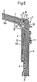
- Fig. 6 of the drawing approximately in natural size - the corner area of an espagnolette fitting 1 for windows, doors or the like is shown, which is composed of two fitting components 2 and 3 which extend essentially at right angles to one another.
- the fitting component 2 has a faceplate 4, while the fitting component 3 has a faceplate 5.
- Both cuff rails 4 and 5 are preferably made of a metallic material, in particular steel. They can be made from strip material with a flat, rectangular cross-section.
- the faceplate 4 of the fitting component 2 carries on its rear side an angled profile guide channel 6 with two straight legs 6a and 6b oriented approximately at right angles to one another, which are connected in one piece by an arcuately curved middle piece 6c.
- a flexible deflection member 7, for example made of spring steel strip or the like is arranged exclusively for longitudinal sliding purposes and is used for the geared connection of drive rods held longitudinally sliding on the back of the two face plates 4 and 5.
- Such a drive rod 8 is guided on the back of the faceplate 5 and together with this forms the fitting component 3.
- a similar drive rod is also provided behind the faceplate 4, but is not shown in FIG. 6 of the drawing.
- drivers are used, of which only the driver 9 is shown in FIG. 6, which projects through a longitudinal slot 10 in the bottom of the profile guide channel 6 and with a driver recess of the drive rod 8 (not shown) , For example, releasably transversely to the adjustment direction of the drive rod 8, is to be brought into engagement.
- the drive rods, for example the drive rod 8, of the drive rod fitting 1 serve to move functional parts, one of which is shown in FIG. 6 and is designed as a locking member 11.
- This locking member 11 is along the outer broad side of the faceplate 5 in the longitudinal direction of which is arranged displaceably and for this purpose is connected via a shaft to the drive rod 8, which has a longitudinal slot (not shown) in the faceplate 5.
- the two fitting components 2 and 3 of the espagnolette fitting 1 can be detachably preassembled with one another via their faceplate 4 and 5 by means of a faceplate corner connection 12 to form a functionally reliable unit on the sash or frame of a window or door.
- this faceplate corner connection 12 can be seen in detail in FIGS. 1 to 5 of the drawing and are subsequently dealt with in detail.
- Fig. 1 of the drawing the frame corner of the wing 13 of a window or a door is shown, on its horizontal leg 14 the faceplate 4 and on its upright leg 15 the faceplate 5 of the drive rod fitting 1 is to be attached.
- the faceplate 4 and 5 have the purpose of covering a drive rod groove 16 leading around the wing corner flush on its open side, with their two longitudinal edges being supported on steps 17 located on the opening side of this drive rod groove 16.
- Screws 18, which penetrate corresponding holes in the faceplate 4 and 5 and are screwed into the bottom of the drive rod groove 16, are used in a known manner to fasten the faceplate 4 and 5 so that the fitting components 2 and 3 on the wing 13.
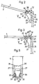
- the faceplate corner connection 12 is provided see. It is formed by a double hook 20 on the faceplate 4 and a complementary matching double hook 21 on the faceplate 5.
- the double hook 20 on the faceplate 4 has an approximately T-shaped outline shape, the free hook ends 22 being directed away from one another.
- the double hook 20 lies completely in the faceplate plane and can therefore be produced by a simple stamping process.
- the coupling flanks 23 on the hook ends 22 of the double hook 20 extend transversely to the main plane of the faceplate 4, but essentially parallel to its transverse edge 24, to which the double hook 20 connects with its web, preferably of the same material.
- the double hook 21 sits on the back of the faceplate 5 and has an approximately C-shaped cross section. It can be formed by a molded part 25, in particular a stamped-bent molded part made of sheet metal, which is firmly connected, for example welded, to the back of the faceplate 5 via a web wall 26. Two tabs 27 are bent from the web wall 26 approximately at right angles as side flanks lying parallel to one another at a distance.
- the flap 28 forming the bottom has a width which corresponds at least approximately to the width of the face plates 4 and 5 and projects on both sides beyond the outer surfaces of the flaps 27 of the molded part 25 which act as side flanks, as can be clearly seen from FIGS. 4 and 5 is.
- flanks forming the side flanks of the double hook 21, which is approximately C-shaped in cross section 27 of the molded part 25 has a gradually increasing width towards the flap 28 forming the bottom along a concave arcuate edge 29, in such a way that the radius of curvature of the edge 29 corresponds to the radius of curvature of the outer surface on the arcuate center piece 6c of the profile guide channel 6 for the flexible deflection member 7 corresponds to that seen in FIG. 6.
- the arcuate curved edge 29 of the two tabs 27 of the molded part 25 thus form a support for the middle piece 6c of the profile guide channel 6, as is shown in FIG. 6.
- the molded part 25 which forms the double hook 21 on the rear side of the faceplate 5 is given its approximately C-shaped cross-sectional shape by the fact that in the two tabs 27, cranks 30 directed from the outside inward are embossed in such a way that they face the ends facing one another from the Form flaps 27 existing side flanks, the clear distance from each other is only slightly larger than the web width of the double hook 20 on the faceplate 4th
- cranks 30 are molded into the tabs 27 of the molded part 25 in such a way that they extend from the inside of the tab 28 forming the bottom only over approximately a third of the total length of the molded part 25.
- the cranks 30 or the mutually formed ends of the side flanks 27 consisting of the tabs 27 formed therefrom have a special shape.
- the relevant surfaces of the cranks 30 run from the inner surface of the flap 28 forming the base approximately at right angles to the base plane, while the subsequent region thereof at an obtuse angle from the web wall 26 is directed away.
- cranks 30 or the ends of the side flanks of the side flanks of the double hook 21 which are approximately C-shaped in cross section and which are formed thereby can be clearly seen in FIGS. 1 to 3 of the drawing.
- the double hook 21 which has the approximately C-shaped cross-sectional shape, carries a nose 31 directed away from the faceplate 5 supporting it at the facing ends 30 of its side flanks forming each other.
- the edge 32 of each tab facing the flap 28, which acts as the bottom of the molded part 25, is at a distance from the inner surface of this bottom or flap 28, which is adapted to the thickness of the faceplate 4.
- the edges 32 of the lugs 31 form effective stops in the direction towards the bottom or tab 28, which support the end of the faceplate 4, which carries the approximately T-shaped double hook 20, on its transverse edges 24, as shown in FIGS dash-dotted lines - also illustrate Fig. 4.
- the faceplate corner connection 12 equipped with the two double hooks 20 and 21 and the lugs 31 enables a three-dimensional positive and non-positive coupling between the faceplate 4 and 5 of the two fitting components 2 and 3 and thus facilitates handling of the connecting rod fitting 1 when it is installed in the wing 13, in particular during the striking process in the area of the wing corners.
Landscapes
- Mechanical Engineering (AREA)
- Engineering & Computer Science (AREA)
- Joining Of Corner Units Of Frames Or Wings (AREA)
- Saccharide Compounds (AREA)
- Compounds Of Unknown Constitution (AREA)
- Enzymes And Modification Thereof (AREA)
- Joining Of Building Structures In Genera (AREA)
- Nonmetallic Welding Materials (AREA)
- Installation Of Indoor Wiring (AREA)
- Superconductors And Manufacturing Methods Therefor (AREA)
- Escalators And Moving Walkways (AREA)
- Forms Removed On Construction Sites Or Auxiliary Members Thereof (AREA)
- Mechanical Coupling Of Light Guides (AREA)
- Transition And Organic Metals Composition Catalysts For Addition Polymerization (AREA)
- Vehicle Step Arrangements And Article Storage (AREA)
- Support Devices For Sliding Doors (AREA)
- Window Of Vehicle (AREA)
Priority Applications (1)
| Application Number | Priority Date | Filing Date | Title |
|---|---|---|---|
| AT88112091T ATE73520T1 (de) | 1987-09-02 | 1988-07-27 | Stulpschienen-eckverbindung. |
Applications Claiming Priority (2)
| Application Number | Priority Date | Filing Date | Title |
|---|---|---|---|
| DE3729215A DE3729215C1 (de) | 1987-09-02 | 1987-09-02 | Stulpschienen-Eckverbindung |
| DE3729215 | 1987-09-02 |
Publications (3)
| Publication Number | Publication Date |
|---|---|
| EP0305731A2 true EP0305731A2 (fr) | 1989-03-08 |
| EP0305731A3 EP0305731A3 (en) | 1990-08-08 |
| EP0305731B1 EP0305731B1 (fr) | 1992-03-11 |
Family
ID=6334992
Family Applications (1)
| Application Number | Title | Priority Date | Filing Date |
|---|---|---|---|
| EP88112091A Expired - Lifetime EP0305731B1 (fr) | 1987-09-02 | 1988-07-27 | Barre de guidage pour un joint d'angle |
Country Status (8)
| Country | Link |
|---|---|
| US (1) | US4837998A (fr) |
| EP (1) | EP0305731B1 (fr) |
| AT (1) | ATE73520T1 (fr) |
| DE (2) | DE3729215C1 (fr) |
| DK (1) | DK159886C (fr) |
| ES (1) | ES2030477T3 (fr) |
| FI (1) | FI86328C (fr) |
| NO (1) | NO166098C (fr) |
Cited By (2)
| Publication number | Priority date | Publication date | Assignee | Title |
|---|---|---|---|---|
| EP1270860A2 (fr) | 2001-06-19 | 2003-01-02 | Mayer & Co. | Crémone |
| WO2007085311A1 (fr) | 2006-01-25 | 2007-08-02 | Siegenia-Aubi Kg | Renvoi d'angle |
Families Citing this family (10)
| Publication number | Priority date | Publication date | Assignee | Title |
|---|---|---|---|---|
| DE9300242U1 (de) * | 1993-01-11 | 1993-03-04 | Mayer & Co., Salzburg | Beschlaganordnung für Flügel von Fenstern oder Türen |
| AUPP449598A0 (en) * | 1998-07-03 | 1998-07-30 | James Hardie Research Pty Limited | Building elements |
| AU743940B2 (en) * | 1998-07-03 | 2002-02-07 | Trend Windows & Doors Pty Limited | Releasable joint |
| DE19834038C2 (de) | 1998-07-29 | 2002-09-19 | Siegenia Frank Kg | Treibstangenbeschlag mit Eckumlenkung |
| DE19901709B4 (de) * | 1999-01-18 | 2004-06-24 | Roto Frank Ag | Fenster- oder Türbeschlag mit wenigstens zwei Stulpschienen |
| DE20201318U1 (de) | 2002-01-29 | 2002-06-20 | Siegenia-Frank Kg, 57074 Siegen | Stulpschienenbeschlag |
| USD500863S1 (en) | 2003-11-04 | 2005-01-11 | Arch-It, Incorporated | Radius corner form |
| US20100242389A1 (en) * | 2009-03-30 | 2010-09-30 | Robert Depaul | Corner wall conduit |
| US8534016B2 (en) * | 2009-03-30 | 2013-09-17 | Robert Depaul | Corner wall conduit |
| CN113802692A (zh) * | 2021-09-30 | 2021-12-17 | 中国十七冶集团有限公司 | 一种预制装配式型钢混凝土主次梁连接结构及连接方法 |
Family Cites Families (5)
| Publication number | Priority date | Publication date | Assignee | Title |
|---|---|---|---|---|
| DE2302538C3 (de) * | 1973-01-19 | 1987-04-16 | Siegenia-Frank Kg, 5900 Siegen | Stulpschienen-Eckverbindung, insbesondere von Treibstangenbeschlägen |
| DE2327086A1 (de) * | 1973-05-28 | 1974-12-19 | Siegenia Frank Kg | Stulpschienen-eckverbindung, insbesondere an treibstangenbeschlaegen |
| DE2365893A1 (de) * | 1973-01-27 | 1976-09-23 | Siegenia Frank Kg | Stulpschienen-eckverbindung, insbesondere von treibstangenbeschlaegen |
| DE2949051A1 (de) * | 1979-12-06 | 1981-06-11 | Carl Fuhr Gmbh & Co, 5628 Heiligenhaus | Drehkippbeschlag fuer fenster, tueren o.dgl. |
| DE3021309C2 (de) * | 1980-06-06 | 1988-05-26 | Carl Fuhr Gmbh & Co, 5628 Heiligenhaus | Hakenverbindung zwischen den Deckschienen eines Treibstangenbeschlags |
-
1987
- 1987-09-02 DE DE3729215A patent/DE3729215C1/de not_active Expired
-
1988
- 1988-07-27 AT AT88112091T patent/ATE73520T1/de not_active IP Right Cessation
- 1988-07-27 ES ES198888112091T patent/ES2030477T3/es not_active Expired - Lifetime
- 1988-07-27 EP EP88112091A patent/EP0305731B1/fr not_active Expired - Lifetime
- 1988-07-27 DE DE8888112091T patent/DE3869020D1/de not_active Expired - Lifetime
- 1988-08-29 US US07/237,968 patent/US4837998A/en not_active Expired - Fee Related
- 1988-08-31 FI FI884006A patent/FI86328C/fi not_active IP Right Cessation
- 1988-09-01 NO NO883890A patent/NO166098C/no unknown
- 1988-09-02 DK DK487288A patent/DK159886C/da not_active IP Right Cessation
Cited By (3)
| Publication number | Priority date | Publication date | Assignee | Title |
|---|---|---|---|---|
| EP1270860A2 (fr) | 2001-06-19 | 2003-01-02 | Mayer & Co. | Crémone |
| EP1270860A3 (fr) * | 2001-06-19 | 2010-02-24 | Mayer & Co. | Crémone |
| WO2007085311A1 (fr) | 2006-01-25 | 2007-08-02 | Siegenia-Aubi Kg | Renvoi d'angle |
Also Published As
| Publication number | Publication date |
|---|---|
| EP0305731B1 (fr) | 1992-03-11 |
| DK487288D0 (da) | 1988-09-02 |
| NO166098C (no) | 1991-05-29 |
| NO883890L (no) | 1989-03-03 |
| FI86328B (fi) | 1992-04-30 |
| DK159886B (da) | 1990-12-24 |
| DK487288A (da) | 1989-03-03 |
| FI884006A0 (fi) | 1988-08-31 |
| US4837998A (en) | 1989-06-13 |
| FI86328C (fi) | 1992-08-10 |
| NO883890D0 (no) | 1988-09-01 |
| DE3869020D1 (de) | 1992-04-16 |
| FI884006L (fi) | 1989-03-03 |
| ATE73520T1 (de) | 1992-03-15 |
| DK159886C (da) | 1991-05-21 |
| ES2030477T3 (es) | 1992-11-01 |
| EP0305731A3 (en) | 1990-08-08 |
| DE3729215C1 (de) | 1989-04-27 |
| NO166098B (no) | 1991-02-18 |
Similar Documents
| Publication | Publication Date | Title |
|---|---|---|
| EP0305731B1 (fr) | Barre de guidage pour un joint d'angle | |
| DE3738300A1 (de) | Fenster, tuer od. dgl. bei dem bzw. der zumindest der fluegelrahmen aus metall- oder kunststoffprofilen zusammengesetzt ist | |
| EP2118414B1 (fr) | Armature de verrouillage et ensemble de pièces pour cette armature | |
| EP0493689B1 (fr) | Tringlerie de commande pour fenêtres, portes ou similaires | |
| EP1159502B1 (fr) | Fenetre ou porte | |
| DE19709283C2 (de) | Kantengetriebe | |
| DE2635446A1 (de) | Laengenverstellbare gestaengekupplung fuer treibstangenbeschlaege an fenstern, tueren o.dgl. | |
| DE3150029C2 (de) | Treibstangenverschluß mit Eckumlenkung für Fenster und Türen od.dgl. | |
| EP0305732A2 (fr) | Barre de guidage pour un joint d'angle | |
| DE19806727A1 (de) | Fenster- oder Türverschluß | |
| DE2709213C2 (de) | Kantengetriebe für ein Fenster, eine Tür o.dgl. | |
| EP0956799B1 (fr) | Cloison pour douches | |
| DE2318408A1 (de) | Schliesstueck mit steg, insbesondere fuer mittelverschluesse an schwenk-kippfenstern | |
| DE2461228C3 (de) | Verfahren zum Herstellen eines an eine jeweils vorgegebene Flügelhöhe angepaßten, einbaufertigen Fenster- oder Türverschlusses | |
| DE9215844U1 (de) | Beschlagteileverbindung | |
| DE19734647B4 (de) | Beschlagteil an einem Flügel oder einem festen Rahmen eines Fensters, einer Tür od. dgl. | |
| DE2805465A1 (de) | Beschlagsbaugruppe fuer fenster, tueren o.dgl. | |
| DE2366635C2 (de) | Stulpschienen-Eckverbindung | |
| DE2236101B2 (de) | T Profilschiene längs der freien vertikalen Stirnseite eines Turblatts, eines Fensterflugeis od dgl | |
| DE8201403U1 (de) | Eckumlenkung für Treibstangenbeschläge von Fenstern, Türen od. dgl. | |
| DE1908478B2 (de) | Treibstangenverbindung | |
| EP0372177A1 (fr) | Renvoi d'angle pour ferrures à tiges actives de fenêtres, portes ou analogues | |
| DE1759040C3 (de) | Beschlag für Fenster oder Türen | |
| DE2304086B2 (de) | Stulpschienen-eckverbindung, insbesondere von treibstangenbeschlaegen | |
| DE2159244B2 (de) | Eckumlenkung für Triebstangenbeschläge |
Legal Events
| Date | Code | Title | Description |
|---|---|---|---|
| PUAI | Public reference made under article 153(3) epc to a published international application that has entered the european phase |
Free format text: ORIGINAL CODE: 0009012 |
|
| AK | Designated contracting states |
Kind code of ref document: A2 Designated state(s): AT BE CH DE ES FR GB IT LI NL SE |
|
| PUAL | Search report despatched |
Free format text: ORIGINAL CODE: 0009013 |
|
| AK | Designated contracting states |
Kind code of ref document: A3 Designated state(s): AT BE CH DE ES FR GB IT LI NL SE |
|
| 17P | Request for examination filed |
Effective date: 19900823 |
|
| 17Q | First examination report despatched |
Effective date: 19910826 |
|
| ITF | It: translation for a ep patent filed | ||
| GRAA | (expected) grant |
Free format text: ORIGINAL CODE: 0009210 |
|
| AK | Designated contracting states |
Kind code of ref document: B1 Designated state(s): AT BE CH DE ES FR GB IT LI NL SE |
|
| PG25 | Lapsed in a contracting state [announced via postgrant information from national office to epo] |
Ref country code: SE Effective date: 19920311 |
|
| REF | Corresponds to: |
Ref document number: 73520 Country of ref document: AT Date of ref document: 19920315 Kind code of ref document: T |
|
| GBT | Gb: translation of ep patent filed (gb section 77(6)(a)/1977) | ||
| REF | Corresponds to: |
Ref document number: 3869020 Country of ref document: DE Date of ref document: 19920416 |
|
| ET | Fr: translation filed | ||
| REG | Reference to a national code |
Ref country code: ES Ref legal event code: FG2A Ref document number: 2030477 Country of ref document: ES Kind code of ref document: T3 |
|
| PLBE | No opposition filed within time limit |
Free format text: ORIGINAL CODE: 0009261 |
|
| STAA | Information on the status of an ep patent application or granted ep patent |
Free format text: STATUS: NO OPPOSITION FILED WITHIN TIME LIMIT |
|
| 26N | No opposition filed | ||
| PGFP | Annual fee paid to national office [announced via postgrant information from national office to epo] |
Ref country code: ES Payment date: 20010706 Year of fee payment: 14 |
|
| PGFP | Annual fee paid to national office [announced via postgrant information from national office to epo] |
Ref country code: BE Payment date: 20010720 Year of fee payment: 14 |
|
| PGFP | Annual fee paid to national office [announced via postgrant information from national office to epo] |
Ref country code: NL Payment date: 20010726 Year of fee payment: 14 |
|
| REG | Reference to a national code |
Ref country code: GB Ref legal event code: IF02 |
|
| PG25 | Lapsed in a contracting state [announced via postgrant information from national office to epo] |
Ref country code: ES Free format text: LAPSE BECAUSE OF NON-PAYMENT OF DUE FEES Effective date: 20020728 |
|
| PGFP | Annual fee paid to national office [announced via postgrant information from national office to epo] |
Ref country code: CH Payment date: 20020730 Year of fee payment: 15 |
|
| PG25 | Lapsed in a contracting state [announced via postgrant information from national office to epo] |
Ref country code: BE Free format text: LAPSE BECAUSE OF NON-PAYMENT OF DUE FEES Effective date: 20020731 |
|
| BERE | Be: lapsed |
Owner name: *SIEGENIA-FRANK K.G. Effective date: 20020731 |
|
| PG25 | Lapsed in a contracting state [announced via postgrant information from national office to epo] |
Ref country code: NL Free format text: LAPSE BECAUSE OF NON-PAYMENT OF DUE FEES Effective date: 20030201 |
|
| NLV4 | Nl: lapsed or anulled due to non-payment of the annual fee |
Effective date: 20030201 |
|
| PG25 | Lapsed in a contracting state [announced via postgrant information from national office to epo] |
Ref country code: LI Free format text: LAPSE BECAUSE OF NON-PAYMENT OF DUE FEES Effective date: 20030731 Ref country code: CH Free format text: LAPSE BECAUSE OF NON-PAYMENT OF DUE FEES Effective date: 20030731 |
|
| REG | Reference to a national code |
Ref country code: CH Ref legal event code: PL |
|
| REG | Reference to a national code |
Ref country code: ES Ref legal event code: FD2A Effective date: 20030811 |
|
| PGFP | Annual fee paid to national office [announced via postgrant information from national office to epo] |
Ref country code: GB Payment date: 20050621 Year of fee payment: 18 |
|
| PGFP | Annual fee paid to national office [announced via postgrant information from national office to epo] |
Ref country code: FR Payment date: 20050713 Year of fee payment: 18 |
|
| PGFP | Annual fee paid to national office [announced via postgrant information from national office to epo] |
Ref country code: AT Payment date: 20050715 Year of fee payment: 18 |
|
| PGFP | Annual fee paid to national office [announced via postgrant information from national office to epo] |
Ref country code: DE Payment date: 20050731 Year of fee payment: 18 |
|
| PG25 | Lapsed in a contracting state [announced via postgrant information from national office to epo] |
Ref country code: GB Free format text: LAPSE BECAUSE OF NON-PAYMENT OF DUE FEES Effective date: 20060727 Ref country code: AT Free format text: LAPSE BECAUSE OF NON-PAYMENT OF DUE FEES Effective date: 20060727 |
|
| PGFP | Annual fee paid to national office [announced via postgrant information from national office to epo] |
Ref country code: IT Payment date: 20060731 Year of fee payment: 19 |
|
| PG25 | Lapsed in a contracting state [announced via postgrant information from national office to epo] |
Ref country code: DE Free format text: LAPSE BECAUSE OF NON-PAYMENT OF DUE FEES Effective date: 20070201 |
|
| GBPC | Gb: european patent ceased through non-payment of renewal fee |
Effective date: 20060727 |
|
| REG | Reference to a national code |
Ref country code: FR Ref legal event code: ST Effective date: 20070330 |
|
| PG25 | Lapsed in a contracting state [announced via postgrant information from national office to epo] |
Ref country code: FR Free format text: LAPSE BECAUSE OF NON-PAYMENT OF DUE FEES Effective date: 20060731 |
|
| PG25 | Lapsed in a contracting state [announced via postgrant information from national office to epo] |
Ref country code: IT Free format text: LAPSE BECAUSE OF NON-PAYMENT OF DUE FEES Effective date: 20070727 |