EP0895344A2 - Verfahren zum Regeln von Drehmomentschwankungen eines Motors mit Permanentmagneten im Inneren und ein Regler mit diesem Verfahren - Google Patents
Verfahren zum Regeln von Drehmomentschwankungen eines Motors mit Permanentmagneten im Inneren und ein Regler mit diesem Verfahren Download PDFInfo
- Publication number
- EP0895344A2 EP0895344A2 EP98114055A EP98114055A EP0895344A2 EP 0895344 A2 EP0895344 A2 EP 0895344A2 EP 98114055 A EP98114055 A EP 98114055A EP 98114055 A EP98114055 A EP 98114055A EP 0895344 A2 EP0895344 A2 EP 0895344A2
- Authority
- EP
- European Patent Office
- Prior art keywords
- torque
- torque ripple
- motor
- waveform
- compensation
- Prior art date
- Legal status (The legal status is an assumption and is not a legal conclusion. Google has not performed a legal analysis and makes no representation as to the accuracy of the status listed.)
- Granted
Links
Images


Classifications
-
- H—ELECTRICITY
- H02—GENERATION; CONVERSION OR DISTRIBUTION OF ELECTRIC POWER
- H02P—CONTROL OR REGULATION OF ELECTRIC MOTORS, ELECTRIC GENERATORS OR DYNAMO-ELECTRIC CONVERTERS; CONTROLLING TRANSFORMERS, REACTORS OR CHOKE COILS
- H02P6/00—Arrangements for controlling synchronous motors or other dynamo-electric motors using electronic commutation dependent on the rotor position; Electronic commutators therefor
- H02P6/10—Arrangements for controlling torque ripple, e.g. providing reduced torque ripple
Definitions
- the present invention relates to a driving motor utilized in an electric vehicle and the like, more specifically, a controlling method of a torque ripple of the motor incorporating an interior permanent magnet and a controller using the same method.
- a shape of a permanent magnet which is to be pasted on a surface of a rotor or a shape of a stator core is modified so that a waveform of an induced voltage which occurs at stator windings can be a sine wave when a rotor is rotated by some means from outside. Then, a driving current of a sine wave is applied to the windings, thereby reducing a torque ripple.
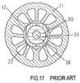
- Fig. 17 is a cross sectional view of the surface permanent magnet type motor which adopts the above method to reduce torque ripples.
- a shaft 24 pierces through and is fixed to the center of rotor core 21 comprising a laminated steel plate.
- a permanent magnet 22 is pasted with glue or the like on the surface of the rotor core 21.
- a shape of the permanent magnet is as follows: both of its inner and outer diameters are convex arc toward outside, and the radial center width is wider than those of both ends.
- the surface permanent magnet type rotor 20 comprises the above elements, i.e., the rotor core 21, magnet 22 and shaft 24.
- a stator 11 has a plurality of teeth 12, and the teeth are provided with windings (not shown.)
- the rotor 20 faces to the stator 11 with an air gap having a narrow clearance in between.
- Fig. 5 is a cross sectional view depicting a structure of the motor having interior permanent magnets
- Fig. 6 illustrates the torque produced by this kind of motor, where the X-axis indicates a current phase supplied to the stator windings and the Y-axis indicates a magnitude of the torque.
- a curve 51 represents a torque produced by the magnet (hereinafter called "magnet torque")
- a curve 52 represents a reluctance torque
- a curve 53 represents a combined torque of these two.
- Pn is a number of pairs of the rotor poles
- ⁇ a is an interlinkage magnetic flux between the rotor and stator
- I is a winding current of the stator
- ⁇ is a lead phase angle (electrical angle).
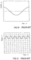
- the first term represents a magnet torque and the second term represents a reluctance torque. Since Ld ⁇ Lq is established in the above equation, the phase of winding current "I" is controlled to advance with regard to the phase of the induced voltage produced in each phase, whereby ⁇ > 0 is realized and a reluctance torque is produced. Thus, comparing with the case with a magnet torque only, the above structure can produce a larger torque at the same current level by setting " ⁇ " at a predetermined value. When the motor having the above interior permanent magnets is driven by the sine wave current shown in Fig. 18, a torque ripple shown in Fig. 19 is produced. This torque ripple is combined by the magnet torque and reluctance torque.
- the motor having the interior permanent magnets has a difficulty in reducing the torque ripple because the produced torque is combined by the magnet torque and reluctance torque although the stator-winding-current is shaped into a sine wave.
- the above description can be summarized as follows:
- the conventional surface-permanent-magnet type motor produces torque due to only the permanent magnets, therefore, the shape of the magnet is modified so that the waveform of induced voltage produced in the stator windings is approximated to a sine wave and the current of sine wave is supplied to the windings, thereby reducing the torque ripple.
- the waveform of the induced voltage produced in the stator windings would be approximated to a sine wave, and the current of the sine wave would be supplied to the windings, the produced torque is combined by the magnet torque and reluctance torque. Therefore, even the torque ripple component due to the permanent magnet can be reduced, the other component due to the reluctance torque cannot be reduced.
- the present invention addresses the above problems and aims to provide a method of controlling torque ripples and a controller using this method for realizing an interior-permanent-magnet type motor having low torque ripples.
- the controlling method of torque ripples produced in the motor having interior permanent magnets and a plurality of phase windings according to the present invention has the following steps:
- the motor is driven by the torque ripple control current through the methods described above, whereby the torque ripple can be reduced.
- the method comprises the steps of:
- the motor is driven by the torque ripple control current, then the torque ripple waves produced in the motor are detected by the torque ripple wave detector and measured by the torque ripple wave measurement circuit sequentially, next, the measured torque ripple waveform is renewed into a new torque compensation waveform sequentially by the torque compensation waveform producing circuit, and then, the renewed torque compensation waveform is multiplied by the basic current to produce a new torque ripple control current, whereby the motor is driven the new torque ripple control current sequentially.
- This method is to control torque ripples through, (1) measuring the torque ripple waves produced in the motor, (2) transforming the measured torque ripple waves into the torque compensation waveforms according to the torque ripple compensation pattern, (3) multiplying the torque compensation waveform by the basic current to produce the torque ripple control current, and (4) supplying the torque ripple control current to the plurality of phase windings, thereby driving the motor.
- the torque ripple produced in the above procedure is detected sequentially by the torque ripple detection means, whereby a feedback control is performed for driving the motor.
- the torque ripple control current is supplied depending on the torque ripple wave produced in the running motor, thereby reducing the torque ripple responsive to a driving situation of the motor.
- a speed sensor is additionally provided to the above steps, and based on a speed detected, in the lower speed area, the motor is driven by the torque ripple control current undergone the torque ripple compensation described above, on the other hand, in the higher speed area, the motor is driven by the basic current namely a supply current having a rectangular or a sine waveform.
- the motor is driven by the basic current namely a supply current having a rectangular or a sine waveform.
- An electric vehicle according to the present invention is driven by the motor having interior permanent magnets.
- the motor is controlled by the above method so that torque is compensated sufficiently to be low torque ripples in a lower speed area where a moment of inertia is so small that the torque ripple causes vibrations, while in a higher speed area, torque compensation is softened because the moment of inertia of the electric vehicle is great.
- the motor having the interior permanent magnets can be driven at a low torque ripple level, and thereby providing a motor control method and a motor controller of high performance.
- the electric vehicle can be operated with less torque ripples and high efficiency.
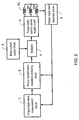
- Fig. 1 is a block diagram depicting a controlling procedure of the torque ripple produced in a motor having interior permanent magnets used in the first exemplary embodiment of the present invention.
- Fig. 5 is a cross sectional view of the motor having interior permanent magnets.
- a stator 30 comprises the following elements: a stator core 31 made of laminated steel plates and consisting of one of twelve blades of teeth 32 and a corresponding yoke 33 which locates at root of the teeth 32, and windings provided to each stator core 31, where these individual stator cores are connected with each other by LASER welding or the like to form a cylinder.
- the twelve blades of teeth 32 are provided with concentrated windings respectively (not shown.) One winding is coupled to the third, sixth and ninth windings counted therefrom in series to form one "U” phase winding. Another winding next to the above winding is also coupled to the third, sixth and ninth windings counted therefrom in series to form one "V” phase winding. In the same manner, the remaining winding is also coupled in series to form one "W" phase winding. These "U”, "V” and “W” phase windings constitute three-phase stator windings.
- a rotor 40 is coaxial with the stator 30 and shapes in cylinder. An outer surface of the rotor 40 faces to an inner surface of the stator 30 via an air-gap having a narrow clearance therebetween.
- the rotor 40 is supported by a bearing (not shown) so that the rotor 40 can rotate on a shaft 44.
- eight slits 42 shaping in "V" letters are punched through axially with an approximate equal interval along a rotational direction of a rotor core 41, and the slits 42 receive permanent magnets 43, whereby eight magnetic poles are formed.
- the permanent magnets are inserted in the slits so that alternate pole N and pole S are arranged sequentially.
- the permanent magnet 43 can be a solid type, which is inserted in the slit 42 and fixed with glue, or the permanent magnet can be a resin type, which is molded in the slit 42 before being magnetized.
- a terminal plate (not shown) is provided on both the ends of the rotor core 41 and riveted with pins (not shown) using through holes (not shown) axially so that the magnets 43 are fixed in the rotor core 41.
- the rotor magnetic pole attracts or repels the teeth 32 of the stator 30 due to rotating magnetic field, whereby the rotor 40 is rotated.
- the motor having interior permanent magnets has three-phase windings, namely, 6U, 6V and 6W, which are driven by currents with a different phase of respective 120° electrical angles.
- a torque ripple is produced in the motor.
- the data of this torque ripple is stored in torque ripple wave memory 1 comprising a semiconductor memory.
- the memory 1 outputs torque ripple waves to torque compensation wave producing circuit 2.
- the wave producing circuit 2 compensates the input torque ripple wave according to a prepared torque ripple compensation pattern, and outputs a torque compensation wave.
- Multiplication circuit 4 receives the torque compensation wave from the wave producing circuit 2 as well as the above basic current, i.e., rectangular waveform current from basic current supply circuit 3, and multiplies these two waves with each other to produce a torque ripple control current, which is fed into torque ripple control current supply circuit 5.
- the current supply circuit 5 supplies a current corresponding to the torque ripple control current to the above three-phase windings, i.e., 6U, 6V and 6W.
- the data of torque ripple wave to be stored in the torque ripple wave memory 1 can be the data of the torque ripple wave actually produced in the motor as above, or data obtained through a numerical analysis such as a finite element method.
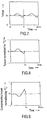
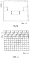
- Fig. 7 depicts the torque ripple when the motor having the permanent magnets is driven by a rectangular current.
- time span "0-t1" is counted one cycle, and the waveform therein is repeated.
- This waveform is stored in the torque ripple wave memory 1.
- the torque compensation wave producing circuit 2 calculates a torque compensation waveform based on the stored data of torque ripple wave. An example of calculating the torque compensation wave in the waveform producing circuit 2 is detailed hereinafter.
- Fig. 9 shows a waveform, where a sign (+,-) is inverted when the waveform in Fig. 8 is greater than "0", and the size is doubled and the sign is inverted when the waveform in Fig. 8 is smaller than "0".
- the waveform in Fig. 9 is used as one cycle of the torque compensation waveform.
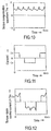
- Fig. 10 shows a torque compensation waveform "Tm", where the waveforms per cycle as shown in Fig. 9 constitute an entire waveform, which is then normalized by "1".
- Fig. 11 shows a rectangular current waveform tapped off from the basic current supply circuit 3, and the multiplier 4 multiplies the rectangular waveform current by the torque compensation waveform "Tm", thereby calculating the torque ripple control current shown in Fig. 12.
- the torque ripple control current supply circuit 5 shown in Fig. 1 supplies the torque ripple control current to the three-phase windings 6U, 6V and 6W sequentially through shifting the phase by 120° electrical angle respectively, whereby the torque ripple is canceled and reduced.
- Fig. 2 is a block diagram depicting a controlling procedure of the torque ripple produced in a motor having interior permanent magnets used in the second exemplary embodiment of the present invention.
- the motor with the interior permanent magnets has three-phase windings 6U, 6V and 6W, to which currents are supplied with a phase shift of 120° electrical angle respectively, thereby the motor is rotated.
- the basic current e.g., a rectangular waveform current
- the torque ripple produced in the motor is detected by torque ripple wave detector 9, and a detected torque ripple wave is measured by torque ripple wave measurement circuit 7.
- the torque compensation wave producing circuit 8 transforms the measured torque ripple waves into torque compensation waves according to the torque ripple compensation pattern.
- the compensation pattern generates torque compensation waves where a difference between the measured torque value and the torque reference value is deducted from the reference value when a torque value of the measured torque ripple waveform exceeds the torque reference value, or generates a torque compensation wave in which the absolute difference therebetween is doubled and added to the reference value when the torque value of the measured torque ripple waveform is lower than the torque reference value.
- the multiplier 4 multiplies the torque compensation waveform by the rectangular waveform current supplied from the basic current supply circuit 3 to produce the torque ripple control current.
- the torque ripple control current supply circuit 5 supplies respective currents corresponding to the torque control currents thus obtained to the three-phase windings 6U, 6V and 6W. Further, a torque ripple wave produced at this time is measured by the torque ripple wave measuring means 7, and the resulted measurement is fed into the torque compensation waveform producing circuit 8, then the above compensation steps are repeated for feedback control, whereby the motor is driven.
- the motor is driven under feedback control, whereby the torque ripples are further suppressed to the lover level than the case of the first exemplary embodiment, where the torque ripple control current is supplied based on the stored data of the torque ripple wave.
- the pattern of the torque compensation waveform produced in the torque compensation waveform producing circuit 8 preferably takes the following described forms.
- Fig. 7 set the torque reference value at T 0 , and produce the torque compensation waveform where the difference between the measured torque value and the torque reference value is deducted from T 0 as shown in Fig. 9 when the torque value of the torque ripple waveform exceeds the torque reference value T 0 .
- the torque compensation waveform formed by the doubled difference is produced as shown in Fig. 9.
- the torque compensation waveform producing circuit 8 outputs the pattern "Tm" of the torque compensation waveform as shown in Fig. 10 to the multiplier 4.
- the basic current supply circuit 3 outputs the rectangular waveform current "I” as shown in Fig. 11 to the multiplier 4, which multiplies the pattern "Tm” by the rectangular waveform current "I” to output the torque ripple control current (I ⁇ Tm) to the torque ripple control current supply circuit 5.
- the current supply circuit 5 supplies currents responsive to the torque ripple control current (I ⁇ Tm) to the three-phase windings comprising U, V and W phases.
- the method of controlling torque ripples as described above can substantially reduce the torque ripples produced in the motor having the interior permanent magnets therein and concentrated windings on the stator.
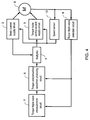
- Fig. 3 is a block diagram depicting a controlling procedure of the torque ripple produced in a motor having interior permanent magnets used in the third exemplary embodiment of the present invention.
- a speed sensor 10 detecting a rotational speed of a motor 6 is provided, and based on the detected speed, compensation is performed at a lower speed area, thereby driving the motor by a supplied current from the torque ripple control current supply circuit 5, and the compensation is not performed at a higher speed area, thereby driving the motor by the basic current from the basic current supply circuit 3.
- the above basic current can be a rectangular wave current or a sine wave current.
- the speed sensor 10 is provided to the third exemplary embodiment, and based on the detected speed, the current supply to the motor 6 is switched to the torque ripple control current supply circuit 5 or the basic current supply circuit 3.
- a pattern of the torque ripple substantially depends on the shapes of rotor and stator of the motor 6, therefore, the patterns of compensation current waveforms for reducing the torque ripple are tabled in the torque compensation waveform producing circuit 2, and the waveform can be compensated by using this table upon request.
- the multiplier 4 multiples the compensated waveform by the basic current, and supplies the multiplication result to the motor 6 via the torque ripple control current supply circuit 5.
- the basic current from the basic current supply circuit 3 is supplied directly to the motor 6.
- the motor in the lower speed area, the motor is driven by the torque ripple control current to which the torque ripple compensation is provided, and in the higher speed area, the motor can be driven by the basic current, e.g., a rectangular waveform current or a sine waveform current without the torque ripple compensation. Therefore, the torque ripple is at a low level in the lower speed area where a moment of inertia is small, and the conventional motor control using the basic current is available in the higher speed area where moment of inertia is great.
- the basic current e.g., a rectangular waveform current or a sine waveform current without the torque ripple compensation. Therefore, the torque ripple is at a low level in the lower speed area where a moment of inertia is small, and the conventional motor control using the basic current is available in the higher speed area where moment of inertia is great.
- the motor can be driven in an efficiency-oriented manner, and further, the conventional motor control can be utilized, therefore, the motor structure can be simplified and the cost can be reduced.
- the basic current in this embodiment can be a form of a current with a combined waveform of rectangular and sine waves.
- a modification of the third exemplary embodiment is available as follows: in the higher speed area, based on the detected speed by the speed sensor 10, the motor can be driven by the torque ripple control current compensated by the smaller compensation value of the torque ripple than that of in the lower speed area, whereby an optimum control responding to a subject motor and load moment of inertia driven by the subject motor can be realized.
- the above optimum control is particularly effective to a subject which is heavy in weight and has a large moment of inertia, such as a motor employed as a driving source of an electric vehicle.
- a status of the torque ripple compensation can be selected before being actualized depending on a size of a moment of inertia and a requested performance.
- Fig. 4 is a block diagram depicting a controlling procedure of the torque ripple produced in a motor having interior permanent magnets used in the fourth exemplary embodiment of the present invention.
- a speed sensor 10 detecting a rotational speed of a motor 6 is provided, and based on the detected speed, compensation is performed at a lower speed area, thereby driving the motor by a supplied current from the torque ripple control current supply circuit 5, and the compensation is not performed at a higher speed area, thereby driving the motor by the basic current from the basic current supply circuit 3.
- the speed sensor 10 is provided, and based on the detected speed, the current supply to the motor is switched to the torque ripple control current supply circuit 5 or the basic current supply circuit 3.
- the motor is driven by the compensated torque-ripple-control-current using a feedback control, whereby the torque ripple can be suppressed more effectively than in the first and third exemplary embodiments where the torque ripple control current is supplied based on the stored data of torque ripple wave in order to drive the motor.
- the motor is driven by the current of the rectangular wave or the sine wave supplied from the basic current supply circuit.
- the motor in the lower speed area where a moment of inertia is small, the motor is driven by the torque ripple control current to which the torque ripple compensation is provided. In the higher speed area where the moment of inertia is large, the motor can be driven by the basic current as it is, and further, an efficiency-oriented drive can be realized.
- the elements comprising the circuits shown in Figs. 1, 2, 3 and 4 also can comprise not only analog circuits but also digital circuits, or software using a micro-computer.
- the motor with the interior permanents magnets is described to have concentrated windings, and in general, the concentrated winding produces greater torque ripples than a distribution winding does. Therefore, the control method of torque ripple according to the present invention is extraordinary effective to the motor employing the concentrated windings.
- the distributed winding is, in the case of three-phase windings, e.g., the U phase winding strides over three adjoining teeth, V phase winding also strides over another three adjacent teeth shifted from the above U phase winding by one tooth, and W phase winding strides over yet another three adjacent teeth shifted from the above V phase winding by one tooth.
- This kind of distributed windings in general, produce less torque ripples than the concentrated windings do; however, if the control method of the present invention is employed in the motor with the distributed windings, the torque ripple can be further suppressed.
- the torque ripple control method for the motor with the interior permanent magnets and the controller using the same method according to the present invention are not only applicable to the driving motor of the electric vehicle, but also to a hermetic motor mounted in a compressor of an air-conditioner, because load torque of the hermetic motor varies great amount, and thus the control method and the controller contribute to reduce the large torque ripple, and yet, this contribution marks a great industrial value.
Landscapes
- Engineering & Computer Science (AREA)
- Power Engineering (AREA)
- Control Of Motors That Do Not Use Commutators (AREA)
- Control Of Ac Motors In General (AREA)
Applications Claiming Priority (3)
| Application Number | Priority Date | Filing Date | Title |
|---|---|---|---|
| JP20411497 | 1997-07-30 | ||
| JP204114/97 | 1997-07-30 | ||
| JP20411497 | 1997-07-30 |
Publications (3)
| Publication Number | Publication Date |
|---|---|
| EP0895344A2 true EP0895344A2 (de) | 1999-02-03 |
| EP0895344A3 EP0895344A3 (de) | 1999-09-01 |
| EP0895344B1 EP0895344B1 (de) | 2003-10-01 |
Family
ID=16485052
Family Applications (1)
| Application Number | Title | Priority Date | Filing Date |
|---|---|---|---|
| EP98114055A Expired - Lifetime EP0895344B1 (de) | 1997-07-30 | 1998-07-28 | Verfahren zum Regeln von Drehmomentschwankungen eines Motors mit Permanentmagneten im Inneren und ein Regler mit diesem Verfahren |
Country Status (3)
| Country | Link |
|---|---|
| US (1) | US5962999A (de) |
| EP (1) | EP0895344B1 (de) |
| DE (1) | DE69818585T2 (de) |
Cited By (2)
| Publication number | Priority date | Publication date | Assignee | Title |
|---|---|---|---|---|
| DE102011089998A1 (de) | 2011-12-27 | 2013-06-27 | Robert Bosch Gmbh | Verfahren und Vorrichtung zur Regelung der Stellung eines Stellglieds eines Stellgebers |
| EP2355333A3 (de) * | 2010-02-08 | 2017-01-11 | Lg Electronics Inc. | Vorrichtung zum Antreiben eines Klimaanlagenkompressors und Verfahren dafür |
Families Citing this family (36)
| Publication number | Priority date | Publication date | Assignee | Title |
|---|---|---|---|---|
| EP0823771B1 (de) | 1996-02-23 | 2006-04-26 | Matsushita Electric Industrial Co., Ltd. | Motor |
| WO2001020767A1 (en) * | 1999-09-17 | 2001-03-22 | Delphi Technologies, Inc. | Low ripple permanent magnet motor control |
| WO2001077812A1 (en) | 2000-04-07 | 2001-10-18 | Delphi Technologies, Inc. | Damping of voltage-controlled brushless motors for electric power steering systems |
| US6498451B1 (en) | 2000-09-06 | 2002-12-24 | Delphi Technologies, Inc. | Torque ripple free electric power steering |
| US6566829B1 (en) | 2000-09-07 | 2003-05-20 | Delphi Technologies, Inc. | Method and apparatus for torque control of a machine |
| JP4009589B2 (ja) | 2001-06-08 | 2007-11-14 | デルファイ・テクノロジーズ・インコーポレーテッド | 電気パワーステアリングシステムのための速度補償制御 |
| US7071649B2 (en) | 2001-08-17 | 2006-07-04 | Delphi Technologies, Inc. | Active temperature estimation for electric machines |
| US7199549B2 (en) * | 2001-08-17 | 2007-04-03 | Delphi Technologies, Inc | Feedback parameter estimation for electric machines |
| US6900607B2 (en) * | 2001-08-17 | 2005-05-31 | Delphi Technologies, Inc. | Combined feedforward and feedback parameter estimation for electric machines |
| US20030076064A1 (en) * | 2001-08-17 | 2003-04-24 | Kleinau Julie A. | Feedforward parameter estimation for electric machines |
| US7576506B2 (en) | 2001-12-11 | 2009-08-18 | Delphi Technologies, Inc. | Feedforward parameter estimation for electric machines |
| US6756757B2 (en) * | 2002-05-21 | 2004-06-29 | Emerson Electric Company | Control system and method for a rotating electromagnetic machine |
| US7157878B2 (en) * | 2002-11-19 | 2007-01-02 | Delphi Technologies, Inc. | Transient compensation voltage estimation for feedforward sinusoidal brushless motor control |
| US20040189228A1 (en) * | 2003-03-28 | 2004-09-30 | Gregory Katch | Vehicle speed dependent compensator for electric steering systems |
| JP3988757B2 (ja) * | 2004-07-28 | 2007-10-10 | ブラザー工業株式会社 | モータ制御装置、モータ制御方法、及びプログラム |
| DE102004039044A1 (de) * | 2004-08-11 | 2006-02-23 | OCé PRINTING SYSTEMS GMBH | Anordnung zum Antrieb eines Lastelementes |
| JP3672919B1 (ja) * | 2004-08-17 | 2005-07-20 | 山洋電気株式会社 | 永久磁石型回転モータ |
| US7248989B2 (en) * | 2005-08-18 | 2007-07-24 | General Motors Corporation | Speed measurement system for speed control of high-speed motors |
| US7549504B2 (en) | 2006-07-28 | 2009-06-23 | Delphi Technologies, Inc. | Quadrant dependent active damping for electric power steering |
| US7543679B2 (en) | 2006-07-28 | 2009-06-09 | Delphi Technologies, Inc. | Compensation of periodic sensor errors in electric power steering systems |
| US7609014B2 (en) * | 2006-10-19 | 2009-10-27 | Rockwell Automation Technologies, Inc. | System and method for universal adaptive torque control of permanent magnet motors |
| US7725227B2 (en) | 2006-12-15 | 2010-05-25 | Gm Global Technology Operations, Inc. | Method, system, and apparatus for providing enhanced steering pull compensation |
| CN103138518A (zh) * | 2011-11-28 | 2013-06-05 | 台达电子工业股份有限公司 | 三相轴向磁通马达及其磁路调控方法 |
| US8924082B2 (en) | 2012-03-30 | 2014-12-30 | Steering Solutions Ip Holding Corporation | System and method for controlling a motor |
| US9663139B2 (en) | 2013-02-26 | 2017-05-30 | Steering Solutions Ip Holding Corporation | Electric motor feedforward control utilizing dynamic motor model |
| US9136785B2 (en) | 2013-03-12 | 2015-09-15 | Steering Solutions Ip Holding Corporation | Motor control system to compensate for torque ripple |
| US9143081B2 (en) | 2013-03-14 | 2015-09-22 | Steering Solutions Ip Holding Corporation | Motor control system having bandwidth compensation |
| WO2014145018A2 (en) | 2013-03-15 | 2014-09-18 | Levant Power Corporation | Active vehicle suspension improvements |
| US10254374B2 (en) * | 2013-07-16 | 2019-04-09 | Ford Global Technologies, Llc | Method of current sensor related torque error estimation for IPMSM e-drive system |
| US10389289B2 (en) | 2014-02-06 | 2019-08-20 | Steering Solutions Ip Holding Corporation | Generating motor control reference signal with control voltage budget |
| CN104953737B (zh) * | 2014-03-26 | 2019-03-22 | 德昌电机(深圳)有限公司 | 一种永磁无刷电机 |
| US10003285B2 (en) | 2014-06-23 | 2018-06-19 | Steering Solutions Ip Holding Corporation | Decoupling current control utilizing direct plant modification in electric power steering system |
| US9809247B2 (en) | 2015-01-30 | 2017-11-07 | Steering Solutions Ip Holding Corporation | Motor control current sensor loss of assist mitigation for electric power steering |
| JP6173520B1 (ja) * | 2016-04-19 | 2017-08-02 | 三菱電機株式会社 | 回転電機の制御装置 |
| US10135368B2 (en) | 2016-10-01 | 2018-11-20 | Steering Solutions Ip Holding Corporation | Torque ripple cancellation algorithm involving supply voltage limit constraint |
| US12308779B2 (en) | 2020-04-01 | 2025-05-20 | Cummins Inc. | Torque ripple compensation in a motor control system |
Family Cites Families (9)
| Publication number | Priority date | Publication date | Assignee | Title |
|---|---|---|---|---|
| US4680526A (en) * | 1984-08-21 | 1987-07-14 | Hitachi, Ltd. | Method of controlling inverter-driven induction motor |
| US4651068A (en) * | 1984-10-01 | 1987-03-17 | Electro-Craft Corporation | Brushless motor control circuitry with optimum current vector control |
| JPH07118950B2 (ja) * | 1986-04-14 | 1995-12-18 | 株式会社日立製作所 | Pwmインバータの制御方法と装置 |
| JPH02206389A (ja) * | 1989-01-31 | 1990-08-16 | Daikin Ind Ltd | リラクタンスモータのトルク脈動低減方法 |
| US5223775A (en) * | 1991-10-28 | 1993-06-29 | Eml Research, Inc. | Apparatus and related method to compensate for torque ripple in a permanent magnet electric motor |
| US5642461A (en) * | 1994-11-14 | 1997-06-24 | Seagate Technology, Inc. | Economical wide range speed control system |
| JP3302235B2 (ja) * | 1995-09-29 | 2002-07-15 | 三菱電機株式会社 | 電動機の位置制御装置 |
| JP3321356B2 (ja) * | 1996-05-20 | 2002-09-03 | 株式会社日立製作所 | モータ制御装置及び電気車用制御装置 |
| US5850132A (en) * | 1997-07-02 | 1998-12-15 | Allin-Bradley Company, Llc | Apparatus used with AC motors for compensating for turn on delay errors |
-
1998
- 1998-07-28 EP EP98114055A patent/EP0895344B1/de not_active Expired - Lifetime
- 1998-07-28 DE DE69818585T patent/DE69818585T2/de not_active Expired - Lifetime
- 1998-07-29 US US09/126,020 patent/US5962999A/en not_active Expired - Fee Related
Cited By (3)
| Publication number | Priority date | Publication date | Assignee | Title |
|---|---|---|---|---|
| EP2355333A3 (de) * | 2010-02-08 | 2017-01-11 | Lg Electronics Inc. | Vorrichtung zum Antreiben eines Klimaanlagenkompressors und Verfahren dafür |
| DE102011089998A1 (de) | 2011-12-27 | 2013-06-27 | Robert Bosch Gmbh | Verfahren und Vorrichtung zur Regelung der Stellung eines Stellglieds eines Stellgebers |
| WO2013097976A2 (de) | 2011-12-27 | 2013-07-04 | Robert Bosch Gmbh | Verfahren und vorrichtung zur regelung der stellung eines stellglieds eines stellgebers |
Also Published As
| Publication number | Publication date |
|---|---|
| EP0895344A3 (de) | 1999-09-01 |
| DE69818585D1 (de) | 2003-11-06 |
| DE69818585T2 (de) | 2004-08-05 |
| EP0895344B1 (de) | 2003-10-01 |
| US5962999A (en) | 1999-10-05 |
Similar Documents
| Publication | Publication Date | Title |
|---|---|---|
| US5962999A (en) | Method of controlling a torque ripple of a motor having interior permanent magnets and a controller using the same method | |
| EP1083649B1 (de) | Motorsystem zum Erreichen eines hohen Wirkungsgrades und Verfahren zur Regelung des Motors | |
| EP1283581A2 (de) | Läufer für einen Permanentmagnetmotor | |
| JP5477161B2 (ja) | ダブルステータ型モータ | |
| JP3306977B2 (ja) | 電気自動車用駆動装置 | |
| US6700240B2 (en) | Stepping motor, stepping motor device and driving method thereof | |
| EP3454469B1 (de) | Reduzierung der drehmomentwelligkeit für einen generator und windturbine damit | |
| EP2006999B1 (de) | Motor/Generator mit axialem Luftspalt | |
| JPH1198791A (ja) | ブラシレスdcモータ | |
| US6376955B1 (en) | Motor/generator with multiple rotors | |
| JP5543186B2 (ja) | スイッチドリラクタンスモータ駆動システム | |
| US9742323B2 (en) | Phase control circuit for brushless motor, brushless motor and method for controlling the phase of brushless motor | |
| US7109624B2 (en) | Synchronous electric machine | |
| JP3117164B2 (ja) | 永久磁石回転電機とその制御方法及び制御装置並びにそれを使用した電気自動車 | |
| JP3284712B2 (ja) | 同期機のロータ構造および同期型モータ | |
| US7342330B2 (en) | Hybrid type double three-phase electric rotating machine | |
| JPH08331885A (ja) | 同期モータ制御装置および制御方法 | |
| US12278523B2 (en) | Electrical machine | |
| JP2008141803A (ja) | ブラシレスモータ | |
| JP3289635B2 (ja) | 永久磁石回転電機装置 | |
| US20250062710A1 (en) | Rotating electric machine control device and rotating electric machine control method | |
| JP3137560B2 (ja) | 同期モータ制御装置 | |
| JPH11103588A (ja) | 永久磁石埋め込み型モータのトルク脈動制御方法及び制御装置 | |
| WO2018110458A1 (ja) | 界磁巻線型回転電機 | |
| JP2002325476A (ja) | モータ装置 |
Legal Events
| Date | Code | Title | Description |
|---|---|---|---|
| PUAI | Public reference made under article 153(3) epc to a published international application that has entered the european phase |
Free format text: ORIGINAL CODE: 0009012 |
|
| AK | Designated contracting states |
Kind code of ref document: A2 Designated state(s): DE FR GB |
|
| AX | Request for extension of the european patent |
Free format text: AL;LT;LV;MK;RO;SI |
|
| PUAL | Search report despatched |
Free format text: ORIGINAL CODE: 0009013 |
|
| AK | Designated contracting states |
Kind code of ref document: A3 Designated state(s): AT BE CH CY DE DK ES FI FR GB GR IE IT LI LU MC NL PT SE |
|
| AX | Request for extension of the european patent |
Free format text: AL;LT;LV;MK;RO;SI |
|
| 17P | Request for examination filed |
Effective date: 19991116 |
|
| AKX | Designation fees paid |
Free format text: DE FR GB |
|
| 17Q | First examination report despatched |
Effective date: 20011016 |
|
| GRAH | Despatch of communication of intention to grant a patent |
Free format text: ORIGINAL CODE: EPIDOS IGRA |
|
| GRAS | Grant fee paid |
Free format text: ORIGINAL CODE: EPIDOSNIGR3 |
|
| GRAA | (expected) grant |
Free format text: ORIGINAL CODE: 0009210 |
|
| AK | Designated contracting states |
Kind code of ref document: B1 Designated state(s): DE FR GB |
|
| REG | Reference to a national code |
Ref country code: GB Ref legal event code: FG4D |
|
| REF | Corresponds to: |
Ref document number: 69818585 Country of ref document: DE Date of ref document: 20031106 Kind code of ref document: P |
|
| ET | Fr: translation filed | ||
| PLBE | No opposition filed within time limit |
Free format text: ORIGINAL CODE: 0009261 |
|
| STAA | Information on the status of an ep patent application or granted ep patent |
Free format text: STATUS: NO OPPOSITION FILED WITHIN TIME LIMIT |
|
| 26N | No opposition filed |
Effective date: 20040702 |
|
| PGFP | Annual fee paid to national office [announced via postgrant information from national office to epo] |
Ref country code: GB Payment date: 20090722 Year of fee payment: 12 |
|
| PGFP | Annual fee paid to national office [announced via postgrant information from national office to epo] |
Ref country code: FR Payment date: 20100805 Year of fee payment: 13 Ref country code: DE Payment date: 20100721 Year of fee payment: 13 |
|
| GBPC | Gb: european patent ceased through non-payment of renewal fee |
Effective date: 20100728 |
|
| PG25 | Lapsed in a contracting state [announced via postgrant information from national office to epo] |
Ref country code: GB Free format text: LAPSE BECAUSE OF NON-PAYMENT OF DUE FEES Effective date: 20100728 |
|
| REG | Reference to a national code |
Ref country code: FR Ref legal event code: ST Effective date: 20120330 |
|
| PG25 | Lapsed in a contracting state [announced via postgrant information from national office to epo] |
Ref country code: FR Free format text: LAPSE BECAUSE OF NON-PAYMENT OF DUE FEES Effective date: 20110801 Ref country code: DE Free format text: LAPSE BECAUSE OF NON-PAYMENT OF DUE FEES Effective date: 20120201 |
|
| REG | Reference to a national code |
Ref country code: DE Ref legal event code: R119 Ref document number: 69818585 Country of ref document: DE Effective date: 20120201 |