EP0895367B1 - Einrichtung zum Anschluss an ein SDH-Richtfunkgerät - Google Patents
Einrichtung zum Anschluss an ein SDH-Richtfunkgerät Download PDFInfo
- Publication number
- EP0895367B1 EP0895367B1 EP98111819A EP98111819A EP0895367B1 EP 0895367 B1 EP0895367 B1 EP 0895367B1 EP 98111819 A EP98111819 A EP 98111819A EP 98111819 A EP98111819 A EP 98111819A EP 0895367 B1 EP0895367 B1 EP 0895367B1
- Authority
- EP
- European Patent Office
- Prior art keywords
- connection
- sdh
- directional radio
- connection device
- driver
- Prior art date
- Legal status (The legal status is an assumption and is not a legal conclusion. Google has not performed a legal analysis and makes no representation as to the accuracy of the status listed.)
- Expired - Lifetime
Links
- 238000012806 monitoring device Methods 0.000 claims description 15
- 230000008054 signal transmission Effects 0.000 claims 1
- 230000005540 biological transmission Effects 0.000 description 6
- 238000010586 diagram Methods 0.000 description 4
- 238000005259 measurement Methods 0.000 description 3
- 238000012544 monitoring process Methods 0.000 description 3
- 238000013461 design Methods 0.000 description 2
- 230000001360 synchronised effect Effects 0.000 description 2
- 238000012360 testing method Methods 0.000 description 2
- 238000011161 development Methods 0.000 description 1
- 230000005669 field effect Effects 0.000 description 1
- 238000012545 processing Methods 0.000 description 1
- 238000010079 rubber tapping Methods 0.000 description 1
Images

Classifications
-
- H—ELECTRICITY
- H04—ELECTRIC COMMUNICATION TECHNIQUE
- H04J—MULTIPLEX COMMUNICATION
- H04J3/00—Time-division multiplex systems
- H04J3/02—Details
- H04J3/14—Monitoring arrangements
-
- H—ELECTRICITY
- H04—ELECTRIC COMMUNICATION TECHNIQUE
- H04J—MULTIPLEX COMMUNICATION
- H04J2203/00—Aspects of optical multiplex systems other than those covered by H04J14/05 and H04J14/07
- H04J2203/0001—Provisions for broadband connections in integrated services digital network using frames of the Optical Transport Network [OTN] or using synchronous transfer mode [STM], e.g. SONET, SDH
- H04J2203/0028—Local loop
- H04J2203/003—Medium of transmission, e.g. fibre, cable, radio
- H04J2203/0035—Radio
-
- H—ELECTRICITY
- H04—ELECTRIC COMMUNICATION TECHNIQUE
- H04J—MULTIPLEX COMMUNICATION
- H04J2203/00—Aspects of optical multiplex systems other than those covered by H04J14/05 and H04J14/07
- H04J2203/0001—Provisions for broadband connections in integrated services digital network using frames of the Optical Transport Network [OTN] or using synchronous transfer mode [STM], e.g. SONET, SDH
- H04J2203/0057—Operations, administration and maintenance [OAM]
- H04J2203/006—Fault tolerance and recovery
Definitions
- the invention relates to an adapter device for connection to a SDH radio relay device.
- SDH Serial Digital Hierarchy
- DRS 155 or DRS 2x155 / 4000, 6200, 6800 and 13000 systems from BoschInstitute have been in operation since 1991 and were put into operation in the new federal states at the time.
- the SDH microwave network was mainly expanded to provide the digital TV network for ARD and ZDF in 1996/1997.
- High demands are placed on the quality and availability of the corresponding transmission channels.
- criteria are transmitted with the actual payload. These are information indicating, for example, a receiver failure (MLE), line error (LFI), or radio field error (FFI).
- MLE receiver failure
- LFI line error
- FFI radio field error
- This information or criteria are from Replacement switching devices are evaluated, which are connected to a connection field of the radio relay. For example, if they detect a line error, they will see to it that they switch to a parallel line over which the same data flows.
- This digital directional radio monitoring device can not be connected to the SDH-Richtfunktieri, for example, the aforementioned type DRS155 or DRS 2 x 155/4000, 6200, 6800 and 13000 from Bosch-Telekom, not. There is no possibility of connecting the monitoring device to the lines transmitting the criteria without influencing the transmission itself.
- the object of the present invention is to provide an adapter device, which opens up a cost-effective way to use existing digital microwave radio monitoring devices that have been used for PDH-Richtfunktieri so far, for monitoring SDH radio equipment.
- an adapter device having the features of claim 1. Due to the fact that the adapter device has a decoupling device, the criteria can be tapped from the connection field of the SDH directional radio without changing it itself, that is, for example, lowering the voltage.
- This decoupling device has a driver module which generates an input signal corresponding to the output signal without the input signal would be affected. This can be achieved, for example, with field effect transistors.
- a plurality of data lines which connect two connection devices of the adapter device with each other, each associated with a driver element of the driver module, wherein the driver module is designed as a CMOS circuit.
- a resistance field is provided, via which the inputs of the driver elements are supplied with a positive voltage.
- each driver element is followed by a resistor.
- both connection devices are designed as multi-pin plug and / or socket strips. Preferably 25-pin strips are used.
- both the decoupling device and the two connecting devices are arranged in a common housing, so that a very compact design is achieved.
- each connection device is assigned a fastening element, in particular in the form of a screw connection.
- a section of a radio relay station 1 is shown in the form of a block diagram.
- Such a radio relay station is used to transmit data transmitted by radio or cable data of 155 Mbit / s, which in addition to television and radio signals also contain telephone or other data signals, to another radio relay station.
- These signals which can be labeled as useful signals, are usually transmitted simultaneously via two channels or lines, so that, if one line fails, it can be switched to the second line without interruption.
- information signals hereinafter referred to as criteria, are added to the useful signals.
- the criteria include, for example, radio field error pulses (FFI), line error pulses (LFI) and receiver failure pulses (MLE).
- FFI radio field error pulses
- LFI line error pulses
- MLE receiver failure pulses
- the radio relay system 1 comprises at least one SDH (Synchronous Digital Hierachy) -Richtfunkêt 3, which is, for example, the type DRS 155 or DRS 2 x 155 of the company BoschInstitut.
- SDH Serial Digital Hierachy
- the directional radio device 3 is associated with a so-called connection panel 5, which offers connection options for various other devices. Thus, for example, it provides a connection option for an equivalent switching device 7 via a plug connection.
- the replacement switching device 7 has the task to evaluate the supplied criteria and detect errors in the radio connection. If, for example, such errors occur in the connection, the substitute switching device 7, which virtually acts as a diverter, does not forward the useful data of the faulty line but the useful data of the parallel second line.
- an adapter 9 is connected, which performs an implementation of the criteria, so that they are connected by a connected to the adapter 9 digital radio relay monitoring device 11 can be received and evaluated.
- the digital radio-monitoring device 11 is designed so that errors are both locally recognizable by the staff, as well as for example by modem and data line at a remote location are queried.
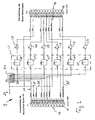
- FIG. 2 shows a circuit diagram of the adapter 9.
- the adapter 9 comprises a connector block 13 formed as a plug, which is formed in the present embodiment 25-pin in the form of a conventional DB-25 connector 15. This plug 25 is inserted into a designated socket in the connection box 5.
- the first terminal block 13 opposite is a second terminal block 17, which is also formed 25-pin in the form of a conventional DB-25 socket 19.
- a decoupling device 23 In order to achieve an electrical decoupling between the two terminal strips 13, 17, a decoupling device 23 is provided.
- This decoupling device 23 comprises a number of decoupling elements 25 corresponding to the number of criteria to be transmitted, each of which is introduced into a line.
- the decoupling elements 25 are preferably CMOS driver modules. With the help of these driver chips 25, it is possible to electrically implement the criteria without power, that is, without affecting the voltage of Kriteria. This is made possible by means of a voltage supply 27, which supplies the driver components 25 with a voltage VCC.
- Each of the driver chips 25 is a resistor 29 downstream, wherein the resistors 29 has the task of preventing short circuits in a faulty wiring of the bushing 19.
- the adapter 9 furthermore has a resistance field 31, which comprises a number of individual resistors 33 corresponding to the number of criteria.
- the six resistors 33 in the present case are connected on the one hand to the power supply 27 and on the other hand each with a criteria line 21. With the help of this wiring, it is possible to create a unique potential on the criteria lines 21 in different applications.
- This adapter 9 thus allows a tapping of the criteria on the pad 5, without affecting the signal level, since the decoupling device 23, in particular the driver chips 25 an electrical Implement the criteria.
- the signal level is independent of the circuit at the socket 19. Since the intended for the replacement switching device 7 connection option is not electrically isolated from the connection option for the adapter 9 and the digital directional radio monitoring device 11, can be with the help of the adapter 9 an influence of Avoid criteria by the connection of the digital radio-monitoring device 11. Without such a decoupling would be influenced by the connection of the digital radio-monitoring device 11, the levels of the criteria with the result that the replacement switching device 7 operates incorrectly.
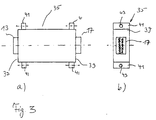
- the elements of the adapter 9 described in Figure 2 are, as shown in Figure 3, housed in a rectangular housing 35, wherein the terminal strips 13 and 17 survive at the two longitudinal ends 37, 39, so that they easily to corresponding terminal blocks on the connection panel 5 and can be connected to the digital radio-monitoring device 11.
- plates 41 are provided on the housing 35 in the region of the longitudinal sides 37, 39. These extend perpendicular to the longitudinal axis of the housing 35 and each have a bore 43. Through these holes 43 screws are performed and bolted to the opposite terminal block of the pad 5 and the digital directional radio monitoring device 11.
Landscapes
- Engineering & Computer Science (AREA)
- Computer Networks & Wireless Communication (AREA)
- Signal Processing (AREA)
- Radio Relay Systems (AREA)
- Monitoring And Testing Of Transmission In General (AREA)
- Transceivers (AREA)
- Transmitters (AREA)
Description
- Die Erfindung betrifft eine Adaptereinrichtung zum Anschluß an ein SDH-Richtfunk-Gerät.
- SDH-Richtfunkanlagen (SDH = Synchrone digitale Hierarchie) des Typs DRS 155 bzw. DRS 2x155/4000, 6200, 6800 und 13000 der Firma Bosch Telekom sind seit 1991 in Betrieb und wurden seinerzeit in den neuen Bundesländern in Betrieb genommen. In den alten Bundesländern wurde das SDH-Richtfunknetz hauptsächlich zur Bereitstellung des digitalen TV-Netzes für ARD und ZDF 1996/1997 ausgebaut. An die Qualität und Verfügbarkeit der entsprechenden Übertragungskanäle werden dabei hohe Anforderungen gestellt. Um eine Qualitätsprüfung durchführen zu können, werden mit den eigentlichen Nutzdaten sogenannte Kriterien übertragen. Es handelt sich hierbei um Informationen, die beispielsweise einen Empfängerausfall (MLE), Linienfehler (LFI) oder Funkfeldfehler (FFI) anzeigen. Diese Informationen beziehungsweise Kriterien werden von Ersatzschaltgeräten ausgewertet, die an einem Anschlußfeld des Richtfunkgeräts angeschlossen sind. Erkennen sie beispielsweise einen Linienfehler, so werden sie dafür sorgen, daß auf eine parallele Leitung, über die die gleichen Daten fließen, umgeschaltet wird.
- Diese mitübertragenen Kriterien lassen sich momentan jedoch nicht dazu nutzen, die Qualität der Leitung zu überwachen und Hinweise über Störungsort und gestörtes Gerät zu erhalten. Bei älteren sogenannten PDH-Richtfunkgeräten wurde zur Überwachen eine Digitale-Richtfunk-Überwachungseinrichtung an das Richtfunkgerät angeschlossen. Mit Hilfe dieser Überwachungseinrichtung (im folgenden kurz Drüwe genannt) konnte auch von einem beliebigen Ort aus über eine Fernleitung eine Abfrage über die Qualität der Leitung durchgeführt werden.
- Diese Digitale-Richtfunk-Überwachungseinrichtung läßt sich bei den SDH-Richtfunktgeräten, beispielsweise des bereits erwähnten Typs DRS155 beziehungsweise DRS 2 x 155/4000, 6200, 6800 und 13000 der Firma Bosch-Telekom, nicht anschließen. Es fehlt eine Möglichkeit, die Überwachungseinrichtung an die die Kriterien übertragenden Leitungen anzuschließen, ohne die Übertragung selbst zu beeinflussen.
- Aus der Veröffentlichung "ROUGIER A: 'TRANSMISSION TESTING: MORE CAPABILITY WITHOUT ADDED COMPLEXITY' TELECOM-MUNICATIONS, DEDHAM, US, Bd. 29, Nr. 8, 1. August 1995 (1995-08-01), Seiten 25-26,28, XP000614831 ISSN: 0040-2494" ist es bekannt, dass Messungen in gemischten PDH/SDH-Netzwerken neue Anforderungen stellen. Es wird darauf hingewiesen, dass neue Testgeräte einen PDH-Analysator und einen SDH-Analysator aufweisen müssen. Es wird aber kein Hinweis darauf gegeben, wie ältere, ausschließlich PDH-fähige digitale Richtfunküberwachungseinrichtungen bei Messungen an einem SDH-Richtfunkgerät eingesetzt werden können.
- Die technische Standardisierungsschrift "'G.772 General aspects of digital transmission systems. Protected monitoring points provided on digital transmission systems.' ITU-T, [Online] März 1993 (1993-03), XP002211219 Gefunden im Internet: <URL:www.ihserc.com> [gefunden am 2002-08-26]" führt aus, welche Spezifikationen/Charakteristiken geschützte Messpunkte (protected monitoring points) aufweisen sollten, um eine Vereinheitlichung der geschützten Messpunkte zu erzielen.
- Das Dokument '"SDH/PDH-MESSZWILLINGE UNTER EINEM HUT' TELCOM REPORT, SIEMENS AG, MUNCHEN, DE, Bd. 18, Nr. 2, 1. März 1995 (1995-03-01), XP000510939 ISSN: 0344-4724" zeigt ein vollständiges Messgerät auf, welches über einen PDH-Analysator und einen SDH-Analysator verfügt. Eine Weiterverwendung von älteren, ausschließlich PDH-fähigen digitalen Richtfunküberwachungseinrichtungen an einem SDH-Richtfunkgerät wird dabei nicht thematisiert.
- Die Aufgabe der vorliegenden Erfindung besteht darin, eine Adaptereinrichtung zu schaffen, die eine kostengünstige Möglichkeit eröffnet, vorhandene digitale Richtfunk-Überwachungseinrichtungen, die bisher für PDH-Richtfunktgeräte eingesetzt wurden, auch zur Überwachung von SDH-Richtfunkgeräten zu nutzen.
- Diese Aufgabe wird durch eine Adaptereinrichtung gelöst, die die Merkmale des Anspruchs 1 aufweist. Dadurch, daß die Adaptereinrichtung eine Entkoppelungsvorrichtung aufweist, können die Kriterien aus dem Anschlußfeld des SDH-Richtfunks abgegriffen werden, ohne diese selbst zu verändern, das heißt beispielsweise die Spannung abzusenken. Diese Entkoppelungsvorrichtung weist einen Treiberbaustein auf, der ein dem Eingangssignal entsprechendes Ausgangssignal generiert, ohne daß das Eingangssignal beeinflußt würde. Dies läßt sich beispielsweise mit Feldeffekttransistoren erreichen. Mehreren Datenleitungen, die zwei Anschlußvorrichtungen der Adaptereinrichtung miteinander verbinden, ist je ein Treiberelement des Treiberbausteins zugeordnet, wobei der Treiberbaustein als CMOS-Schaltung ausgebildet ist. Darüber hinaus ist ein Widerstandsfeld vorgesehen, über das die Eingänge der Treiberelemente mit einer positiven Spannung beaufschlagt sind.
- In einer weiteren vorteilhaften Ausgestaltung der Erfindung ist jedem Treiberelement ein Widerstand nachgeordnet.
- In einer vorteilhaften Weiterbildung der Erfindung sind beide Anschlußvorrichtungen als mehrpolige Stecker- und/oder Buchsenleisten ausgebildet. Vorzugsweise werden 25-polige Leisten benutzt.
- In einer vorteilhaften Weiterbildung der Erfindung sind sowohl die Entkoppelungsvorrichtung als auch die beiden Anschlußvorrichtungen in einem gemeinsamen Gehäuse angeordnet, so daß eine sehr kompakte Bauweise erreicht wird.
- In einer vorteilhaften Weiterbildung der Erfindung ist jeder Anschlußvorrichtung ein Befestigungselement, insbesondere in Form einer Schraubverbindung, zugeordnet.
- Die Erfindung wird nun anhand eines Ausführungsbeispiels mit Bezug auf die Zeichnung näher erläutert. Dabei zeigen:
- Figur 1
- eine schematische Blockdarstellung eines digitalen Richtfunksystems,
- Figur 2
- ein Schaltbild der Adaptereinrichtung, und
- Figur 3a und 3b
- eine Seiten- und Frontansicht der Adaptereinrichtung.
- In Figur 1 ist in Form eines Blockschaltbildes ein Ausschnitt einer Richtfunkstation 1 dargestellt. Eine solche Richtfunkstation dient dazu, per Richtfunk oder per Kabel angelieferte Datenströme von 155 Mbit/s, die neben Fernseh- und Rundfunksignale auch Telefon- oder andere Datensignale enthalten, an eine weitere Richtfunkstation zu übertragen. Zur Erhöhung der Verfügbarkeit und der Übertragungsqualität werden diese als Nutzsignale bezeichenbare Signale üblicherweise über zwei Kanäle beziehungsweise Leitungen zeitgleich übertragen, so daß bei Ausfall einer Leitung unterbrechungslos auf die zweite Leitung umgeschaltet werden kann. Um Störungen zu erkennen, werden mit den Nutzsignalen Informationssignale, im folgenden als Kriterien bezeichnet, hinzuaddiert. Die Kriterien umfassen beispielsweise Funkfeldfehlerimpulse (FFI), Linienfehlerimpulse (LFI) und Empfängerausfallimpulse (MLE). Unter Funkfeld ist hierbei das sich zwischen dem Sender und dem Empfänger erstreckende Gebiet (Feld) zu verstehen.
- Die Richtfunkanlage 1 umfaßt zumindest ein SDH(Synchrone digitale Hierachie)-Richtfunkgerät 3, bei dem es sich beispielsweise um den Typ DRS 155 beziehungsweise DRS 2 x 155 der Firma Bosch-Telekom handelt. Dem Richtfunkgerät 3 ist ein sogenanntes Anschlußfeld 5 zugeordnet, das Anschlußmöglichkeiten für diverse andere Geräte bietet. So stellt es beispielsweise eine Anschlußmöglichkeit für ein Ersatzschaltgerät 7 über eine Steckverbindung zur Verfügung. Das Ersatzschaltgerät 7 hat die Aufgabe, die zugeführten Kriterien auszuwerten und Fehler in der Funkverbindung festzustellen. Treten beispielsweise solche Fehler in der Verbindung auf, so leitet das quasi als Weiche dienende Ersatzschaltgerät 7 nicht die Nutzdaten der gestörten Leitung sondern die Nutzdaten der parallelen zweiten Leitung weiter.
- An einem weiteren Anschluß des Anschlußfeldes 5 ist ein Adapter 9 angeschlossen, der eine Umsetzung der Kriterien durchführt, so daß sie von einer am Adapter 9 angeschlossenen digitalen Richtfunk-Überwachungseinrichtung 11 empfangen und ausgewertet werden können. Die digitale Richtfunk-Überwachungeinrichtung 11 ist so ausgelegt, daß Fehler sowohl vor Ort durch das Personal erkennbar sind, als auch beispielsweise per Modem und Datenleitung an einem fernen Ort abfragbar sind.
- In Figur 2 ist ein Schaltbild des Adapters 9 dargestellt. Der Adapter 9 umfaßt eine als Stecker ausgebildete Anschlußleiste 13, die im vorliegenden Ausführungsbeispiel 25-polig in Form eines üblichen DB-25-Steckers 15 ausgebildet ist. Dieser Stecker 25 wird in eine dafür vorgesehene Buchse im Anschlußfeld 5 eingesteckt.
- Der ersten Anschlußleiste 13 gegenüber liegt eine zweite Anschlußleiste 17, die ebenfalls 25-polig in Form einer üblichen DB-25-Buchse 19 ausgebildet ist.
- Die vom Anschlußfeld 5 bereitgestellten Kriterien, im vorliegenden Ausführungsbeispiel handelt es sich hierbei um die Signale LFI1, LFI2, FFI1, FFI2, MLE1, MLE2 werden über Leitungen 21 von den Kontakten des Steckers 15 zu den entsprechenden Kontakten der Buchse 19 geführt.
- Um eine elektrische Entkoppelung zwischen den beiden Anschlußleisten 13, 17 zu erreichen, ist eine Entkoppelungsvorrichtung 23 vorgesehen. Diese Entkoppelungsvorrichtung 23 umfaßt eine der Anzahl der zu übertragenden Kriterien entsprechende Anzahl an Entkopplungselementen 25, die jeweils in eine Leitung eingebracht sind. Bei den Entkopplungselementen 25 handelt es sich vorzugsweise um CMOS-Treiberbausteine. Mit Hilfe dieser Treiberbausteine 25 ist es möglich, die Kriterien leistungslos, das heißt ohne Beeinflussung der Spannung des Kriterieums elektrisch umzusetzen. Dies wird über eine Spannungsversorgung 27 ermöglicht, die die Treiberbausteine 25 mit einer Spannung VCC versorgt.
- Jedem der Treiberbausteine 25 ist ein Widerstand 29 nachgeordnet, wobei den Widerständen 29 die Aufgabe zukommt, Kurzschlüsse bei einer fehlerhaften Beschaltung der Buchse 19 zu verhindern.
- Der Adapter 9 weist darüber hinaus ein Widerstandsfeld 31 auf, das eine der Zahl der Kriterien entsprechende Anzahl an einzelnen Widerständen 33 umfaßt. Die im vorliegenden Fall sechs Widerstände 33 sind einerseits mit der Spannungsversorgung 27 verbunden und andererseits mit jeweils einer Kriterienleitung 21. Mit Hilfe dieser Beschaltung ist es möglich, auf den Kriterienleitungen 21 bei unterschiedlichen Einsatzfällen ein eindeutiges Potential zu schaffen.
- Neben den bereits erwähnten Kriterienleitungen 21 sind im vorliegenden Ausführungsbeispiel weitere Leitungen 35 für die Versorgungsspannung, für Masse und für die Abschirmung vorgesehen. Diese Leitungen 35 sind jedoch nicht mit der Entkoppelungsvorrichtung 23 verbunden, sondern führen direkt zu den Entsprechenden Kontakten der Buchse 19.
- Dieser Adapter 9 erlaubt also einen Abgriff der Kriterien am Anschlußfeld 5, ohne deren Signalpegel zu beeinflussen, da die Entkopplungsvorrichtung 23, insbesondere die Treiberbausteine 25 eine elektrische Umsetzung der Kriterien durchführen. Damit wird der Signalpegel unabhängig von der Beschaltung an der Buchse 19. Da die für das Ersatzschaltgerät 7 vorgesehene Anschlußmöglichkeit nicht galvanisch getrennt ist von der Anschlußmöglichkeit für den Adapter 9 beziehungsweise die digitale Richtfunk-Überwachungseinrichtung 11, läßt sich mit Hilfe des Adapters 9 eine Beeinflussung der Kriterien durch den Anschluß der digitalen Richtfunk-Überwachungseinrichtung 11 vermeiden. Ohne eine solche Entkoppelung würden durch den Anschluß der digitalen Richtfunk-Überwachungseinrichtung 11 die Pegel der Kriterien beeinflußt mit der Folge, daß das Ersatzschaltgerät 7 fehlerhaft arbeitet.
- Die in Figur 2 beschriebenen Elemente des Adapters 9 sind, wie in Figur 3 dargestellt, in einem rechteckigen Gehäuse 35 untergebracht, wobei an den beiden Längsenden 37, 39 die Anschlußleisten 13 beziehungsweise 17 überstehen, so daß sie leicht an entsprechenden Anschlußleisten am Anschlußfeld 5 beziehungsweise an der digitalen Richtfunk-Überwachungseinrichtung 11 anschließbar sind.
- Um eine sichere Kontaktierung zu ermöglichen, sind an dem Gehäuse 35 im Bereich der Längsseiten 37, 39 Platten 41 vorgesehen. Diese erstrecken sich senkrecht zu der Längsachse des Gehäuses 35 und weisen jeweils eine Bohrung 43 auf. Durch diese Bohrungen 43 werden Schrauben durchgeführt und mit der gegenüberliegenden Anschlußleiste des Anschlußfeldes 5 beziehungsweise der digitalen Richtfunk-Überwachungseinrichtung 11 verschraubt.
- Es zeigt sich, daß ein in seiner Bauform sehr kompakter, kostengünstig herstellbarer Adapter vorliegt, der es ermöglicht, die vorhandenen digitalen Richtfunk-Überwachungseinrichtungen auch bei den neuen SDH-Richtfunkgeräten einzusetzen. Damit kann auf den Einsatz sehr teuerer Abzweigverstärker, die zur Aufbereitung der Signale für die digitale Richtfunk-Überwachungseinrichtung notwendig sind, verzichtet werden.
Claims (6)
- Einrichtung zum Anschluss an ein SDH-Richtfunkgerät mit einer ersten, dem Anschluss an das SDH-Richtfunkgerät dienenden Anschlussvorrichtung (13), dadurch gekennzeichnet, dass die Einrichtung eine Adaptereinrichtung (9) ist, aufweisend eine zweite, dem Anschluss einer digitales, für PDH-Richffunkgeräte bestimmten Richtfunküberwachungseinrichtung dienende Anschlussvorrichtung (17), wobei die erste Anschlussvorrichtung (13) über eine eine rückwirkungsfreie elektrische Signalübertragung vornehmende Entkopplungsvornchtung (23) mit der zweiten Anschlussvorrichtung (17) mittels Daten-Leitungen (21) verbunden ist, wobei die Entkopplungsvorrichtung (23) einen Treiberbaustein umfasst und jeder Daten-Leitung (21) ein als CMOS-Treiberbaustein ausgebildetes Treiberelement (25) des Treiberbausteins zugeordnet ist, und dass ein Widerstandsfeld (31) vorgesehen ist, das eine der Zahl der Daten-Leitungen (21) entsprechende Anzahl von Widerständen (33) umfasst, die einerseits mit einer Spannungsversorgung und andererseits mit jeweils einer Daten-Leitung (21) verbunden sind, und über die die Eingänge der Treiberelemente (25) für eine eindeutige Potentialvorgabe mit einer positiven Spannung beaufschlagt sind.
- Einrichtung nach Anspruch 1, dadurch gekennzeichnet, dass jedem Treiberelement (25) ein Widerstand (29) nachgeordnet ist.
- Einrichtung nach einem oder mehreren der vorhergehenden Ansprüche, dadurch gekennzeichnet, dass die erste Anschlussvorrichtung (13) als mehrpolige, vorzugsweise 25-polige Steckerleiste (15) und die zweite Anschlussvorrichtung (17) als mehrpolige, vor zugsweise 25-polige Buchsenleiste (19) ausgebildet sind.
- Einrichtung nach einem oder mehreren der vorhergehenden Ansprüche, dadurch gekennzeichnet, dass die Entkoppelungsvorrichtung (23) zusammen mit den beiden Anschlussvorrichtungen (13, 17) in einem Gehäuse (35) angeordnet sind.
- Einrichtung nach einem oder mehreren der vorhergehenden Ansprüche, dadurch gekennzeichnet, dass jede Anschlussvorrichtung (13, 17) ein Befestigungselement (41) umfasst, das der wieder lösbaren Verbindung dient.
- Einrichtung nach Anspruch 5, dadurch gekennzeichnet, dass das Befestigungselement (41) als Schraubverbindung ausgelegt ist.
Applications Claiming Priority (2)
| Application Number | Priority Date | Filing Date | Title |
|---|---|---|---|
| DE19733084A DE19733084C2 (de) | 1997-07-31 | 1997-07-31 | Einrichtung zum Anschluß an ein SDH-Richtfunk-Gerät |
| DE19733084 | 1997-07-31 |
Publications (3)
| Publication Number | Publication Date |
|---|---|
| EP0895367A2 EP0895367A2 (de) | 1999-02-03 |
| EP0895367A3 EP0895367A3 (de) | 2002-10-30 |
| EP0895367B1 true EP0895367B1 (de) | 2007-11-21 |
Family
ID=7837550
Family Applications (1)
| Application Number | Title | Priority Date | Filing Date |
|---|---|---|---|
| EP98111819A Expired - Lifetime EP0895367B1 (de) | 1997-07-31 | 1998-06-26 | Einrichtung zum Anschluss an ein SDH-Richtfunkgerät |
Country Status (2)
| Country | Link |
|---|---|
| EP (1) | EP0895367B1 (de) |
| DE (2) | DE19733084C2 (de) |
Family Cites Families (1)
| Publication number | Priority date | Publication date | Assignee | Title |
|---|---|---|---|---|
| WO1997015987A1 (de) * | 1995-10-25 | 1997-05-01 | Siemens Aktiengesellschaft | System zur übertragung von informationen durch einen gemischtbetrieb einer pdh und einer sdh mit einem ersatzübertragungskanal |
-
1997
- 1997-07-31 DE DE19733084A patent/DE19733084C2/de not_active Expired - Fee Related
-
1998
- 1998-06-26 DE DE59814127T patent/DE59814127D1/de not_active Expired - Lifetime
- 1998-06-26 EP EP98111819A patent/EP0895367B1/de not_active Expired - Lifetime
Non-Patent Citations (1)
| Title |
|---|
| None * |
Also Published As
| Publication number | Publication date |
|---|---|
| EP0895367A2 (de) | 1999-02-03 |
| DE59814127D1 (de) | 2008-01-03 |
| DE19733084C2 (de) | 2000-02-24 |
| DE19733084A1 (de) | 1999-02-04 |
| EP0895367A3 (de) | 2002-10-30 |
Similar Documents
| Publication | Publication Date | Title |
|---|---|---|
| DE69735639T2 (de) | Elektronisches bussystem | |
| DE19643092A1 (de) | Feld-Datenbussystem | |
| DE69003891T2 (de) | Testvorrichtung für gedruckte Schaltungskarten und ihre Anwendung für das Testen von gedruckten Schaltungskarten, in Form einer Multiplex-Demultiplexeinrichtung für numerische Signale. | |
| WO2004019456A1 (de) | Verteileranschlussmodul für die telekommunikations- und datentechnik | |
| EP1965482A1 (de) | ASI-Netzwerk für explosionsgefährdete Bereiche | |
| DE19630614A1 (de) | Schaltanlage | |
| EP1687681B1 (de) | Verfahren zum betreiben eines netzwerks | |
| DE10135980C1 (de) | Anordnung zum Anschluß von dezentral und prozessnah angeordneten Feldgeräten an eine entfernte zentrale Einrichtung | |
| EP0540764B1 (de) | Demodulatorbaustein zur Systemüberwachung während des Betriebes | |
| EP1010303B1 (de) | Kommunikationseinrichtung für die übertragung von nachrichtensignalen | |
| EP0287992B1 (de) | Hochverfügbares serielles Bussystem | |
| EP0265837B1 (de) | Schaltungsanordnung, deren Verwendung und Prüfverfahren für ein Nachrichtennetzwerk | |
| DE19916894B4 (de) | Bussystem | |
| EP0551114A1 (de) | Anordnung zur Informationsübermittlung | |
| EP0895367B1 (de) | Einrichtung zum Anschluss an ein SDH-Richtfunkgerät | |
| DE68910427T2 (de) | Optisches Netzwerk. | |
| EP1085691A2 (de) | System zur prozessorgesteuerten Übertragung von elektrischen Signalen und elektrischer Energie innerhalb eines militärischen Fahrzeugs | |
| DE19922467B4 (de) | Verfahren und Vorrichtung zur Trennung von Spannungsquelle und Datenentkopplung bei AS-Interface | |
| EP1236306B1 (de) | Bussystem | |
| DE3529056C2 (de) | ||
| DE102004055053A1 (de) | Netzwerk, insbesondere PROFIBUS PA-Netzwerk, mit Redundanzeigenschaften sowie Abzweigelement für ein Teilnehmergerät in einem derartigen Netzwerk, Redundanzmanager für ein derartiges Netzwerk und Verfahren zum Betreiben eines derartigen Netzwerks | |
| DE3780520T2 (de) | Schnittstelle zur verbindung eines geraets mit einem koaxialen kabel. | |
| EP0728581A2 (de) | Bussystem für eine Druckmaschine | |
| DE19640172A1 (de) | Übertrager-Leistungskopplung | |
| DE3100969C2 (de) | Ankoppelschaltung für die Überwachung einer Vielzahl von Nachrichtenleitungen |
Legal Events
| Date | Code | Title | Description |
|---|---|---|---|
| PUAI | Public reference made under article 153(3) epc to a published international application that has entered the european phase |
Free format text: ORIGINAL CODE: 0009012 |
|
| AK | Designated contracting states |
Kind code of ref document: A2 Designated state(s): AT BE CH CY DE DK ES FI FR GB GR IE IT LI LU MC NL PT SE |
|
| AX | Request for extension of the european patent |
Free format text: AL;LT;LV;MK;RO;SI |
|
| PUAL | Search report despatched |
Free format text: ORIGINAL CODE: 0009013 |
|
| RIC1 | Information provided on ipc code assigned before grant |
Free format text: 7H 04B 7/15 A, 7H 04J 3/14 B |
|
| AK | Designated contracting states |
Kind code of ref document: A3 Designated state(s): AT BE CH CY DE DK ES FI FR GB GR IE IT LI LU MC NL PT SE |
|
| AX | Request for extension of the european patent |
Free format text: AL;LT;LV;MK;RO;SI |
|
| 17P | Request for examination filed |
Effective date: 20030502 |
|
| 17Q | First examination report despatched |
Effective date: 20030610 |
|
| AKX | Designation fees paid |
Designated state(s): AT BE CH CY DE DK ES FI FR GB GR IE IT LI LU MC NL PT SE |
|
| GRAP | Despatch of communication of intention to grant a patent |
Free format text: ORIGINAL CODE: EPIDOSNIGR1 |
|
| GRAS | Grant fee paid |
Free format text: ORIGINAL CODE: EPIDOSNIGR3 |
|
| GRAA | (expected) grant |
Free format text: ORIGINAL CODE: 0009210 |
|
| RTI1 | Title (correction) |
Free format text: APPARATUS FOR CONNECTION TO AN SDH DIRECTIONAL RADIO UNIT |
|
| AK | Designated contracting states |
Kind code of ref document: B1 Designated state(s): AT BE CH CY DE DK ES FI FR GB GR IE IT LI LU MC NL PT SE |
|
| REG | Reference to a national code |
Ref country code: GB Ref legal event code: FG4D Free format text: NOT ENGLISH |
|
| REG | Reference to a national code |
Ref country code: IE Ref legal event code: FG4D Free format text: LANGUAGE OF EP DOCUMENT: GERMAN |
|
| REG | Reference to a national code |
Ref country code: CH Ref legal event code: EP |
|
| REF | Corresponds to: |
Ref document number: 59814127 Country of ref document: DE Date of ref document: 20080103 Kind code of ref document: P |
|
| GBT | Gb: translation of ep patent filed (gb section 77(6)(a)/1977) |
Effective date: 20080130 |
|
| PG25 | Lapsed in a contracting state [announced via postgrant information from national office to epo] |
Ref country code: SE Free format text: LAPSE BECAUSE OF FAILURE TO SUBMIT A TRANSLATION OF THE DESCRIPTION OR TO PAY THE FEE WITHIN THE PRESCRIBED TIME-LIMIT Effective date: 20080221 Ref country code: NL Free format text: LAPSE BECAUSE OF FAILURE TO SUBMIT A TRANSLATION OF THE DESCRIPTION OR TO PAY THE FEE WITHIN THE PRESCRIBED TIME-LIMIT Effective date: 20071121 Ref country code: ES Free format text: LAPSE BECAUSE OF FAILURE TO SUBMIT A TRANSLATION OF THE DESCRIPTION OR TO PAY THE FEE WITHIN THE PRESCRIBED TIME-LIMIT Effective date: 20080304 |
|
| NLV1 | Nl: lapsed or annulled due to failure to fulfill the requirements of art. 29p and 29m of the patents act | ||
| PG25 | Lapsed in a contracting state [announced via postgrant information from national office to epo] |
Ref country code: FI Free format text: LAPSE BECAUSE OF FAILURE TO SUBMIT A TRANSLATION OF THE DESCRIPTION OR TO PAY THE FEE WITHIN THE PRESCRIBED TIME-LIMIT Effective date: 20071121 |
|
| ET | Fr: translation filed | ||
| PG25 | Lapsed in a contracting state [announced via postgrant information from national office to epo] |
Ref country code: DK Free format text: LAPSE BECAUSE OF FAILURE TO SUBMIT A TRANSLATION OF THE DESCRIPTION OR TO PAY THE FEE WITHIN THE PRESCRIBED TIME-LIMIT Effective date: 20071121 |
|
| PLBE | No opposition filed within time limit |
Free format text: ORIGINAL CODE: 0009261 |
|
| STAA | Information on the status of an ep patent application or granted ep patent |
Free format text: STATUS: NO OPPOSITION FILED WITHIN TIME LIMIT |
|
| PG25 | Lapsed in a contracting state [announced via postgrant information from national office to epo] |
Ref country code: PT Free format text: LAPSE BECAUSE OF FAILURE TO SUBMIT A TRANSLATION OF THE DESCRIPTION OR TO PAY THE FEE WITHIN THE PRESCRIBED TIME-LIMIT Effective date: 20080421 |
|
| REG | Reference to a national code |
Ref country code: IE Ref legal event code: FD4D |
|
| 26N | No opposition filed |
Effective date: 20080822 |
|
| PG25 | Lapsed in a contracting state [announced via postgrant information from national office to epo] |
Ref country code: IE Free format text: LAPSE BECAUSE OF FAILURE TO SUBMIT A TRANSLATION OF THE DESCRIPTION OR TO PAY THE FEE WITHIN THE PRESCRIBED TIME-LIMIT Effective date: 20071121 |
|
| BERE | Be: lapsed |
Owner name: DEUTSCHE TELEKOM A.G. Effective date: 20080630 |
|
| PG25 | Lapsed in a contracting state [announced via postgrant information from national office to epo] |
Ref country code: MC Free format text: LAPSE BECAUSE OF NON-PAYMENT OF DUE FEES Effective date: 20080630 Ref country code: GR Free format text: LAPSE BECAUSE OF FAILURE TO SUBMIT A TRANSLATION OF THE DESCRIPTION OR TO PAY THE FEE WITHIN THE PRESCRIBED TIME-LIMIT Effective date: 20080222 |
|
| REG | Reference to a national code |
Ref country code: CH Ref legal event code: PL |
|
| PG25 | Lapsed in a contracting state [announced via postgrant information from national office to epo] |
Ref country code: BE Free format text: LAPSE BECAUSE OF NON-PAYMENT OF DUE FEES Effective date: 20080630 |
|
| PG25 | Lapsed in a contracting state [announced via postgrant information from national office to epo] |
Ref country code: LI Free format text: LAPSE BECAUSE OF NON-PAYMENT OF DUE FEES Effective date: 20080630 Ref country code: CH Free format text: LAPSE BECAUSE OF NON-PAYMENT OF DUE FEES Effective date: 20080630 |
|
| PG25 | Lapsed in a contracting state [announced via postgrant information from national office to epo] |
Ref country code: CY Free format text: LAPSE BECAUSE OF FAILURE TO SUBMIT A TRANSLATION OF THE DESCRIPTION OR TO PAY THE FEE WITHIN THE PRESCRIBED TIME-LIMIT Effective date: 20071121 |
|
| PG25 | Lapsed in a contracting state [announced via postgrant information from national office to epo] |
Ref country code: LU Free format text: LAPSE BECAUSE OF NON-PAYMENT OF DUE FEES Effective date: 20080626 |
|
| PG25 | Lapsed in a contracting state [announced via postgrant information from national office to epo] |
Ref country code: IT Free format text: LAPSE BECAUSE OF NON-PAYMENT OF DUE FEES Effective date: 20080630 |
|
| PGFP | Annual fee paid to national office [announced via postgrant information from national office to epo] |
Ref country code: FR Payment date: 20110630 Year of fee payment: 14 |
|
| PGFP | Annual fee paid to national office [announced via postgrant information from national office to epo] |
Ref country code: GB Payment date: 20110621 Year of fee payment: 14 Ref country code: AT Payment date: 20110620 Year of fee payment: 14 |
|
| PGFP | Annual fee paid to national office [announced via postgrant information from national office to epo] |
Ref country code: DE Payment date: 20110826 Year of fee payment: 14 |
|
| REG | Reference to a national code |
Ref country code: AT Ref legal event code: MM01 Ref document number: 379321 Country of ref document: AT Kind code of ref document: T Effective date: 20120626 |
|
| GBPC | Gb: european patent ceased through non-payment of renewal fee |
Effective date: 20120626 |
|
| REG | Reference to a national code |
Ref country code: FR Ref legal event code: ST Effective date: 20130228 |
|
| REG | Reference to a national code |
Ref country code: DE Ref legal event code: R119 Ref document number: 59814127 Country of ref document: DE Effective date: 20130101 |
|
| PG25 | Lapsed in a contracting state [announced via postgrant information from national office to epo] |
Ref country code: DE Free format text: LAPSE BECAUSE OF NON-PAYMENT OF DUE FEES Effective date: 20130101 Ref country code: FR Free format text: LAPSE BECAUSE OF NON-PAYMENT OF DUE FEES Effective date: 20120702 Ref country code: GB Free format text: LAPSE BECAUSE OF NON-PAYMENT OF DUE FEES Effective date: 20120626 |
|
| PG25 | Lapsed in a contracting state [announced via postgrant information from national office to epo] |
Ref country code: AT Free format text: LAPSE BECAUSE OF NON-PAYMENT OF DUE FEES Effective date: 20120626 |