EP0895367B1 - Système de connection à un équipement de transmission par faisceau hertzien SDH - Google Patents
Système de connection à un équipement de transmission par faisceau hertzien SDH Download PDFInfo
- Publication number
- EP0895367B1 EP0895367B1 EP98111819A EP98111819A EP0895367B1 EP 0895367 B1 EP0895367 B1 EP 0895367B1 EP 98111819 A EP98111819 A EP 98111819A EP 98111819 A EP98111819 A EP 98111819A EP 0895367 B1 EP0895367 B1 EP 0895367B1
- Authority
- EP
- European Patent Office
- Prior art keywords
- connection
- sdh
- directional radio
- connection device
- driver
- Prior art date
- Legal status (The legal status is an assumption and is not a legal conclusion. Google has not performed a legal analysis and makes no representation as to the accuracy of the status listed.)
- Expired - Lifetime
Links
- 238000012806 monitoring device Methods 0.000 claims description 15
- 230000008054 signal transmission Effects 0.000 claims 1
- 230000005540 biological transmission Effects 0.000 description 6
- 238000010586 diagram Methods 0.000 description 4
- 238000005259 measurement Methods 0.000 description 3
- 238000012544 monitoring process Methods 0.000 description 3
- 238000013461 design Methods 0.000 description 2
- 230000001360 synchronised effect Effects 0.000 description 2
- 238000012360 testing method Methods 0.000 description 2
- 238000011161 development Methods 0.000 description 1
- 230000005669 field effect Effects 0.000 description 1
- 238000012545 processing Methods 0.000 description 1
- 238000010079 rubber tapping Methods 0.000 description 1
Images

Classifications
-
- H—ELECTRICITY
- H04—ELECTRIC COMMUNICATION TECHNIQUE
- H04J—MULTIPLEX COMMUNICATION
- H04J3/00—Time-division multiplex systems
- H04J3/02—Details
- H04J3/14—Monitoring arrangements
-
- H—ELECTRICITY
- H04—ELECTRIC COMMUNICATION TECHNIQUE
- H04J—MULTIPLEX COMMUNICATION
- H04J2203/00—Aspects of optical multiplex systems other than those covered by H04J14/05 and H04J14/07
- H04J2203/0001—Provisions for broadband connections in integrated services digital network using frames of the Optical Transport Network [OTN] or using synchronous transfer mode [STM], e.g. SONET, SDH
- H04J2203/0028—Local loop
- H04J2203/003—Medium of transmission, e.g. fibre, cable, radio
- H04J2203/0035—Radio
-
- H—ELECTRICITY
- H04—ELECTRIC COMMUNICATION TECHNIQUE
- H04J—MULTIPLEX COMMUNICATION
- H04J2203/00—Aspects of optical multiplex systems other than those covered by H04J14/05 and H04J14/07
- H04J2203/0001—Provisions for broadband connections in integrated services digital network using frames of the Optical Transport Network [OTN] or using synchronous transfer mode [STM], e.g. SONET, SDH
- H04J2203/0057—Operations, administration and maintenance [OAM]
- H04J2203/006—Fault tolerance and recovery
Definitions
- the invention relates to an adapter device for connection to a SDH radio relay device.
- SDH Serial Digital Hierarchy
- DRS 155 or DRS 2x155 / 4000, 6200, 6800 and 13000 systems from BoschInstitute have been in operation since 1991 and were put into operation in the new federal states at the time.
- the SDH microwave network was mainly expanded to provide the digital TV network for ARD and ZDF in 1996/1997.
- High demands are placed on the quality and availability of the corresponding transmission channels.
- criteria are transmitted with the actual payload. These are information indicating, for example, a receiver failure (MLE), line error (LFI), or radio field error (FFI).
- MLE receiver failure
- LFI line error
- FFI radio field error
- This information or criteria are from Replacement switching devices are evaluated, which are connected to a connection field of the radio relay. For example, if they detect a line error, they will see to it that they switch to a parallel line over which the same data flows.
- This digital directional radio monitoring device can not be connected to the SDH-Richtfunktieri, for example, the aforementioned type DRS155 or DRS 2 x 155/4000, 6200, 6800 and 13000 from Bosch-Telekom, not. There is no possibility of connecting the monitoring device to the lines transmitting the criteria without influencing the transmission itself.
- the object of the present invention is to provide an adapter device, which opens up a cost-effective way to use existing digital microwave radio monitoring devices that have been used for PDH-Richtfunktieri so far, for monitoring SDH radio equipment.
- an adapter device having the features of claim 1. Due to the fact that the adapter device has a decoupling device, the criteria can be tapped from the connection field of the SDH directional radio without changing it itself, that is, for example, lowering the voltage.
- This decoupling device has a driver module which generates an input signal corresponding to the output signal without the input signal would be affected. This can be achieved, for example, with field effect transistors.
- a plurality of data lines which connect two connection devices of the adapter device with each other, each associated with a driver element of the driver module, wherein the driver module is designed as a CMOS circuit.
- a resistance field is provided, via which the inputs of the driver elements are supplied with a positive voltage.
- each driver element is followed by a resistor.
- both connection devices are designed as multi-pin plug and / or socket strips. Preferably 25-pin strips are used.
- both the decoupling device and the two connecting devices are arranged in a common housing, so that a very compact design is achieved.
- each connection device is assigned a fastening element, in particular in the form of a screw connection.
- a section of a radio relay station 1 is shown in the form of a block diagram.
- Such a radio relay station is used to transmit data transmitted by radio or cable data of 155 Mbit / s, which in addition to television and radio signals also contain telephone or other data signals, to another radio relay station.
- These signals which can be labeled as useful signals, are usually transmitted simultaneously via two channels or lines, so that, if one line fails, it can be switched to the second line without interruption.
- information signals hereinafter referred to as criteria, are added to the useful signals.
- the criteria include, for example, radio field error pulses (FFI), line error pulses (LFI) and receiver failure pulses (MLE).
- FFI radio field error pulses
- LFI line error pulses
- MLE receiver failure pulses
- the radio relay system 1 comprises at least one SDH (Synchronous Digital Hierachy) -Richtfunkêt 3, which is, for example, the type DRS 155 or DRS 2 x 155 of the company BoschInstitut.
- SDH Serial Digital Hierachy
- the directional radio device 3 is associated with a so-called connection panel 5, which offers connection options for various other devices. Thus, for example, it provides a connection option for an equivalent switching device 7 via a plug connection.
- the replacement switching device 7 has the task to evaluate the supplied criteria and detect errors in the radio connection. If, for example, such errors occur in the connection, the substitute switching device 7, which virtually acts as a diverter, does not forward the useful data of the faulty line but the useful data of the parallel second line.
- an adapter 9 is connected, which performs an implementation of the criteria, so that they are connected by a connected to the adapter 9 digital radio relay monitoring device 11 can be received and evaluated.
- the digital radio-monitoring device 11 is designed so that errors are both locally recognizable by the staff, as well as for example by modem and data line at a remote location are queried.
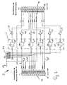
- FIG. 2 shows a circuit diagram of the adapter 9.
- the adapter 9 comprises a connector block 13 formed as a plug, which is formed in the present embodiment 25-pin in the form of a conventional DB-25 connector 15. This plug 25 is inserted into a designated socket in the connection box 5.
- the first terminal block 13 opposite is a second terminal block 17, which is also formed 25-pin in the form of a conventional DB-25 socket 19.
- a decoupling device 23 In order to achieve an electrical decoupling between the two terminal strips 13, 17, a decoupling device 23 is provided.
- This decoupling device 23 comprises a number of decoupling elements 25 corresponding to the number of criteria to be transmitted, each of which is introduced into a line.
- the decoupling elements 25 are preferably CMOS driver modules. With the help of these driver chips 25, it is possible to electrically implement the criteria without power, that is, without affecting the voltage of Kriteria. This is made possible by means of a voltage supply 27, which supplies the driver components 25 with a voltage VCC.
- Each of the driver chips 25 is a resistor 29 downstream, wherein the resistors 29 has the task of preventing short circuits in a faulty wiring of the bushing 19.
- the adapter 9 furthermore has a resistance field 31, which comprises a number of individual resistors 33 corresponding to the number of criteria.
- the six resistors 33 in the present case are connected on the one hand to the power supply 27 and on the other hand each with a criteria line 21. With the help of this wiring, it is possible to create a unique potential on the criteria lines 21 in different applications.
- This adapter 9 thus allows a tapping of the criteria on the pad 5, without affecting the signal level, since the decoupling device 23, in particular the driver chips 25 an electrical Implement the criteria.
- the signal level is independent of the circuit at the socket 19. Since the intended for the replacement switching device 7 connection option is not electrically isolated from the connection option for the adapter 9 and the digital directional radio monitoring device 11, can be with the help of the adapter 9 an influence of Avoid criteria by the connection of the digital radio-monitoring device 11. Without such a decoupling would be influenced by the connection of the digital radio-monitoring device 11, the levels of the criteria with the result that the replacement switching device 7 operates incorrectly.
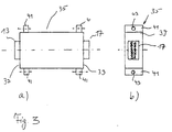
- the elements of the adapter 9 described in Figure 2 are, as shown in Figure 3, housed in a rectangular housing 35, wherein the terminal strips 13 and 17 survive at the two longitudinal ends 37, 39, so that they easily to corresponding terminal blocks on the connection panel 5 and can be connected to the digital radio-monitoring device 11.
- plates 41 are provided on the housing 35 in the region of the longitudinal sides 37, 39. These extend perpendicular to the longitudinal axis of the housing 35 and each have a bore 43. Through these holes 43 screws are performed and bolted to the opposite terminal block of the pad 5 and the digital directional radio monitoring device 11.
Landscapes
- Engineering & Computer Science (AREA)
- Computer Networks & Wireless Communication (AREA)
- Signal Processing (AREA)
- Radio Relay Systems (AREA)
- Monitoring And Testing Of Transmission In General (AREA)
- Transceivers (AREA)
- Transmitters (AREA)
Claims (6)
- Système de connexion à un équipement de transmission par faisceau hertzien SDH, comportant un premier dispositif de connexion (13) servant à la connexion à l'équipement de transmission par faisceau hertzien SDH, caractérisé en ce que le système est un système adaptateur (9) présentant un second dispositif de connexion (17) servant à la connexion d'un système de surveillance de faisceau hertzien numérique destiné à des équipements de transmission par faisceau hertzien PDH, le premier dispositif de connexion (13) étant relié au second dispositif de connexion (17) par l'intermédiaire d'un dispositif de découplage (23) effectuant une transmission de signal électrique exempte de rétroaction et moyennant des lignes de données (21), le dispositif de découplage (23) comprenant un module de pilote et un élément de pilote (25) du module de pilote, réalisé sous la forme d'un module de pilote CMOS, étant affecté à chacune des lignes de données (21), et en ce qu'un champ de résistance (3 1) est prévu qui comprend un nombre de résistances (33) égal au nombre des lignes de données (21), reliées à une alimentation en tension d'une part et respectivement à une ligne de données (21) d'autre part, et par l'intermédiaire desquelles les entrées des éléments de pilote (25) sont alimentées en une tension positive pour une prédétermination univoque du potentiel.
- Système selon la revendication 1, caractérisé en ce qu'une résistance (29) est prévue en aval de chaque élément de pilote (25).
- Système selon l'une ou plusieurs des revendications précédentes, caractérisé en ce que le premier dispositif de connexion (13) est réalisé sous la forme d'un connecteur mâle (15) multibroche, de préférence à 25 pôles, et en ce que le second dispositif de connexion (17) est réalisé sous la forme d'une prise femelle (19) multibroche, de préférence à 25 pôles.
- Système selon l'une ou plusieurs des revendications précédentes, caractérisé en ce que le dispositif de découplage (23) est logé, ensemble avec les deux dispositifs de connexion (13, 17) dans un boîtier (35).
- Système selon l'une ou plusieurs des revendications précédentes, caractérisé en ce que chaque dispositif de connexion (13, 17) comprend un élément de fixation (41) servant à la liaison démontable.
- Système selon la revendication 5, caractérisé en ce que l'élément de fixation (41) est conçu sous la forme d'un assemblage à vis.
Applications Claiming Priority (2)
| Application Number | Priority Date | Filing Date | Title |
|---|---|---|---|
| DE19733084A DE19733084C2 (de) | 1997-07-31 | 1997-07-31 | Einrichtung zum Anschluß an ein SDH-Richtfunk-Gerät |
| DE19733084 | 1997-07-31 |
Publications (3)
| Publication Number | Publication Date |
|---|---|
| EP0895367A2 EP0895367A2 (fr) | 1999-02-03 |
| EP0895367A3 EP0895367A3 (fr) | 2002-10-30 |
| EP0895367B1 true EP0895367B1 (fr) | 2007-11-21 |
Family
ID=7837550
Family Applications (1)
| Application Number | Title | Priority Date | Filing Date |
|---|---|---|---|
| EP98111819A Expired - Lifetime EP0895367B1 (fr) | 1997-07-31 | 1998-06-26 | Système de connection à un équipement de transmission par faisceau hertzien SDH |
Country Status (2)
| Country | Link |
|---|---|
| EP (1) | EP0895367B1 (fr) |
| DE (2) | DE19733084C2 (fr) |
Family Cites Families (1)
| Publication number | Priority date | Publication date | Assignee | Title |
|---|---|---|---|---|
| WO1997015987A1 (fr) * | 1995-10-25 | 1997-05-01 | Siemens Aktiengesellschaft | Systeme de transmission d'informations par fonctionnement mixte d'un pdh et d'un sdh avec un canal de transmission en reserve |
-
1997
- 1997-07-31 DE DE19733084A patent/DE19733084C2/de not_active Expired - Fee Related
-
1998
- 1998-06-26 DE DE59814127T patent/DE59814127D1/de not_active Expired - Lifetime
- 1998-06-26 EP EP98111819A patent/EP0895367B1/fr not_active Expired - Lifetime
Non-Patent Citations (1)
| Title |
|---|
| None * |
Also Published As
| Publication number | Publication date |
|---|---|
| EP0895367A2 (fr) | 1999-02-03 |
| DE59814127D1 (de) | 2008-01-03 |
| DE19733084C2 (de) | 2000-02-24 |
| DE19733084A1 (de) | 1999-02-04 |
| EP0895367A3 (fr) | 2002-10-30 |
Similar Documents
| Publication | Publication Date | Title |
|---|---|---|
| DE69735639T2 (de) | Elektronisches bussystem | |
| DE19643092A1 (de) | Feld-Datenbussystem | |
| DE69003891T2 (de) | Testvorrichtung für gedruckte Schaltungskarten und ihre Anwendung für das Testen von gedruckten Schaltungskarten, in Form einer Multiplex-Demultiplexeinrichtung für numerische Signale. | |
| WO2004019456A1 (fr) | Module de connexion de dispositif de distribution utilise en technique de telecommunication et de traitement de donnees | |
| EP1965482A1 (fr) | Réseau ASI pour des zones en danger d'explosion | |
| DE19630614A1 (de) | Schaltanlage | |
| EP1687681B1 (fr) | Méthode d'opération d'un réseau | |
| DE10135980C1 (de) | Anordnung zum Anschluß von dezentral und prozessnah angeordneten Feldgeräten an eine entfernte zentrale Einrichtung | |
| EP0540764B1 (fr) | Unité de démodulation permettant de contrôler les défaillances du système pendant le fonctionnement | |
| EP1010303B1 (fr) | Dispositif de transmission pour la transmission de signaux de communication | |
| EP0287992B1 (fr) | Système de bus série à haute disponibilité | |
| EP0265837B1 (fr) | Montage de circuit, son application et procédé de contrôle pour un réseau de communication de messages | |
| DE19916894B4 (de) | Bussystem | |
| EP0551114A1 (fr) | Dispositif de communication d'informations | |
| EP0895367B1 (fr) | Système de connection à un équipement de transmission par faisceau hertzien SDH | |
| DE68910427T2 (de) | Optisches Netzwerk. | |
| EP1085691A2 (fr) | Système pour le transfert processeur-commandé des signaux électriques et de l'énergie électrique dans un véhicule militaire | |
| DE19922467B4 (de) | Verfahren und Vorrichtung zur Trennung von Spannungsquelle und Datenentkopplung bei AS-Interface | |
| EP1236306B1 (fr) | Systeme de bus | |
| DE3529056C2 (fr) | ||
| DE102004055053A1 (de) | Netzwerk, insbesondere PROFIBUS PA-Netzwerk, mit Redundanzeigenschaften sowie Abzweigelement für ein Teilnehmergerät in einem derartigen Netzwerk, Redundanzmanager für ein derartiges Netzwerk und Verfahren zum Betreiben eines derartigen Netzwerks | |
| DE3780520T2 (de) | Schnittstelle zur verbindung eines geraets mit einem koaxialen kabel. | |
| EP0728581A2 (fr) | Système de bus pour une machine d'impression | |
| DE19640172A1 (de) | Übertrager-Leistungskopplung | |
| DE3100969C2 (de) | Ankoppelschaltung für die Überwachung einer Vielzahl von Nachrichtenleitungen |
Legal Events
| Date | Code | Title | Description |
|---|---|---|---|
| PUAI | Public reference made under article 153(3) epc to a published international application that has entered the european phase |
Free format text: ORIGINAL CODE: 0009012 |
|
| AK | Designated contracting states |
Kind code of ref document: A2 Designated state(s): AT BE CH CY DE DK ES FI FR GB GR IE IT LI LU MC NL PT SE |
|
| AX | Request for extension of the european patent |
Free format text: AL;LT;LV;MK;RO;SI |
|
| PUAL | Search report despatched |
Free format text: ORIGINAL CODE: 0009013 |
|
| RIC1 | Information provided on ipc code assigned before grant |
Free format text: 7H 04B 7/15 A, 7H 04J 3/14 B |
|
| AK | Designated contracting states |
Kind code of ref document: A3 Designated state(s): AT BE CH CY DE DK ES FI FR GB GR IE IT LI LU MC NL PT SE |
|
| AX | Request for extension of the european patent |
Free format text: AL;LT;LV;MK;RO;SI |
|
| 17P | Request for examination filed |
Effective date: 20030502 |
|
| 17Q | First examination report despatched |
Effective date: 20030610 |
|
| AKX | Designation fees paid |
Designated state(s): AT BE CH CY DE DK ES FI FR GB GR IE IT LI LU MC NL PT SE |
|
| GRAP | Despatch of communication of intention to grant a patent |
Free format text: ORIGINAL CODE: EPIDOSNIGR1 |
|
| GRAS | Grant fee paid |
Free format text: ORIGINAL CODE: EPIDOSNIGR3 |
|
| GRAA | (expected) grant |
Free format text: ORIGINAL CODE: 0009210 |
|
| RTI1 | Title (correction) |
Free format text: APPARATUS FOR CONNECTION TO AN SDH DIRECTIONAL RADIO UNIT |
|
| AK | Designated contracting states |
Kind code of ref document: B1 Designated state(s): AT BE CH CY DE DK ES FI FR GB GR IE IT LI LU MC NL PT SE |
|
| REG | Reference to a national code |
Ref country code: GB Ref legal event code: FG4D Free format text: NOT ENGLISH |
|
| REG | Reference to a national code |
Ref country code: IE Ref legal event code: FG4D Free format text: LANGUAGE OF EP DOCUMENT: GERMAN |
|
| REG | Reference to a national code |
Ref country code: CH Ref legal event code: EP |
|
| REF | Corresponds to: |
Ref document number: 59814127 Country of ref document: DE Date of ref document: 20080103 Kind code of ref document: P |
|
| GBT | Gb: translation of ep patent filed (gb section 77(6)(a)/1977) |
Effective date: 20080130 |
|
| PG25 | Lapsed in a contracting state [announced via postgrant information from national office to epo] |
Ref country code: SE Free format text: LAPSE BECAUSE OF FAILURE TO SUBMIT A TRANSLATION OF THE DESCRIPTION OR TO PAY THE FEE WITHIN THE PRESCRIBED TIME-LIMIT Effective date: 20080221 Ref country code: NL Free format text: LAPSE BECAUSE OF FAILURE TO SUBMIT A TRANSLATION OF THE DESCRIPTION OR TO PAY THE FEE WITHIN THE PRESCRIBED TIME-LIMIT Effective date: 20071121 Ref country code: ES Free format text: LAPSE BECAUSE OF FAILURE TO SUBMIT A TRANSLATION OF THE DESCRIPTION OR TO PAY THE FEE WITHIN THE PRESCRIBED TIME-LIMIT Effective date: 20080304 |
|
| NLV1 | Nl: lapsed or annulled due to failure to fulfill the requirements of art. 29p and 29m of the patents act | ||
| PG25 | Lapsed in a contracting state [announced via postgrant information from national office to epo] |
Ref country code: FI Free format text: LAPSE BECAUSE OF FAILURE TO SUBMIT A TRANSLATION OF THE DESCRIPTION OR TO PAY THE FEE WITHIN THE PRESCRIBED TIME-LIMIT Effective date: 20071121 |
|
| ET | Fr: translation filed | ||
| PG25 | Lapsed in a contracting state [announced via postgrant information from national office to epo] |
Ref country code: DK Free format text: LAPSE BECAUSE OF FAILURE TO SUBMIT A TRANSLATION OF THE DESCRIPTION OR TO PAY THE FEE WITHIN THE PRESCRIBED TIME-LIMIT Effective date: 20071121 |
|
| PLBE | No opposition filed within time limit |
Free format text: ORIGINAL CODE: 0009261 |
|
| STAA | Information on the status of an ep patent application or granted ep patent |
Free format text: STATUS: NO OPPOSITION FILED WITHIN TIME LIMIT |
|
| PG25 | Lapsed in a contracting state [announced via postgrant information from national office to epo] |
Ref country code: PT Free format text: LAPSE BECAUSE OF FAILURE TO SUBMIT A TRANSLATION OF THE DESCRIPTION OR TO PAY THE FEE WITHIN THE PRESCRIBED TIME-LIMIT Effective date: 20080421 |
|
| REG | Reference to a national code |
Ref country code: IE Ref legal event code: FD4D |
|
| 26N | No opposition filed |
Effective date: 20080822 |
|
| PG25 | Lapsed in a contracting state [announced via postgrant information from national office to epo] |
Ref country code: IE Free format text: LAPSE BECAUSE OF FAILURE TO SUBMIT A TRANSLATION OF THE DESCRIPTION OR TO PAY THE FEE WITHIN THE PRESCRIBED TIME-LIMIT Effective date: 20071121 |
|
| BERE | Be: lapsed |
Owner name: DEUTSCHE TELEKOM A.G. Effective date: 20080630 |
|
| PG25 | Lapsed in a contracting state [announced via postgrant information from national office to epo] |
Ref country code: MC Free format text: LAPSE BECAUSE OF NON-PAYMENT OF DUE FEES Effective date: 20080630 Ref country code: GR Free format text: LAPSE BECAUSE OF FAILURE TO SUBMIT A TRANSLATION OF THE DESCRIPTION OR TO PAY THE FEE WITHIN THE PRESCRIBED TIME-LIMIT Effective date: 20080222 |
|
| REG | Reference to a national code |
Ref country code: CH Ref legal event code: PL |
|
| PG25 | Lapsed in a contracting state [announced via postgrant information from national office to epo] |
Ref country code: BE Free format text: LAPSE BECAUSE OF NON-PAYMENT OF DUE FEES Effective date: 20080630 |
|
| PG25 | Lapsed in a contracting state [announced via postgrant information from national office to epo] |
Ref country code: LI Free format text: LAPSE BECAUSE OF NON-PAYMENT OF DUE FEES Effective date: 20080630 Ref country code: CH Free format text: LAPSE BECAUSE OF NON-PAYMENT OF DUE FEES Effective date: 20080630 |
|
| PG25 | Lapsed in a contracting state [announced via postgrant information from national office to epo] |
Ref country code: CY Free format text: LAPSE BECAUSE OF FAILURE TO SUBMIT A TRANSLATION OF THE DESCRIPTION OR TO PAY THE FEE WITHIN THE PRESCRIBED TIME-LIMIT Effective date: 20071121 |
|
| PG25 | Lapsed in a contracting state [announced via postgrant information from national office to epo] |
Ref country code: LU Free format text: LAPSE BECAUSE OF NON-PAYMENT OF DUE FEES Effective date: 20080626 |
|
| PG25 | Lapsed in a contracting state [announced via postgrant information from national office to epo] |
Ref country code: IT Free format text: LAPSE BECAUSE OF NON-PAYMENT OF DUE FEES Effective date: 20080630 |
|
| PGFP | Annual fee paid to national office [announced via postgrant information from national office to epo] |
Ref country code: FR Payment date: 20110630 Year of fee payment: 14 |
|
| PGFP | Annual fee paid to national office [announced via postgrant information from national office to epo] |
Ref country code: GB Payment date: 20110621 Year of fee payment: 14 Ref country code: AT Payment date: 20110620 Year of fee payment: 14 |
|
| PGFP | Annual fee paid to national office [announced via postgrant information from national office to epo] |
Ref country code: DE Payment date: 20110826 Year of fee payment: 14 |
|
| REG | Reference to a national code |
Ref country code: AT Ref legal event code: MM01 Ref document number: 379321 Country of ref document: AT Kind code of ref document: T Effective date: 20120626 |
|
| GBPC | Gb: european patent ceased through non-payment of renewal fee |
Effective date: 20120626 |
|
| REG | Reference to a national code |
Ref country code: FR Ref legal event code: ST Effective date: 20130228 |
|
| REG | Reference to a national code |
Ref country code: DE Ref legal event code: R119 Ref document number: 59814127 Country of ref document: DE Effective date: 20130101 |
|
| PG25 | Lapsed in a contracting state [announced via postgrant information from national office to epo] |
Ref country code: DE Free format text: LAPSE BECAUSE OF NON-PAYMENT OF DUE FEES Effective date: 20130101 Ref country code: FR Free format text: LAPSE BECAUSE OF NON-PAYMENT OF DUE FEES Effective date: 20120702 Ref country code: GB Free format text: LAPSE BECAUSE OF NON-PAYMENT OF DUE FEES Effective date: 20120626 |
|
| PG25 | Lapsed in a contracting state [announced via postgrant information from national office to epo] |
Ref country code: AT Free format text: LAPSE BECAUSE OF NON-PAYMENT OF DUE FEES Effective date: 20120626 |