EP0895434A1 - Appareil électronique, en particulier appareil de radiocommunication, du type susceptible de basculer entre au moins deux modes de fonctionnement - Google Patents
Appareil électronique, en particulier appareil de radiocommunication, du type susceptible de basculer entre au moins deux modes de fonctionnement Download PDFInfo
- Publication number
- EP0895434A1 EP0895434A1 EP98401749A EP98401749A EP0895434A1 EP 0895434 A1 EP0895434 A1 EP 0895434A1 EP 98401749 A EP98401749 A EP 98401749A EP 98401749 A EP98401749 A EP 98401749A EP 0895434 A1 EP0895434 A1 EP 0895434A1
- Authority
- EP
- European Patent Office
- Prior art keywords
- standby
- main chain
- electronic device
- main
- mode
- Prior art date
- Legal status (The legal status is an assumption and is not a legal conclusion. Google has not performed a legal analysis and makes no representation as to the accuracy of the status listed.)
- Granted
Links
Images
Classifications
-
- H—ELECTRICITY
- H04—ELECTRIC COMMUNICATION TECHNIQUE
- H04W—WIRELESS COMMUNICATION NETWORKS
- H04W52/00—Power management, e.g. Transmission Power Control [TPC] or power classes
- H04W52/02—Power saving arrangements
- H04W52/0209—Power saving arrangements in terminal devices
- H04W52/0225—Power saving arrangements in terminal devices using monitoring of external events, e.g. the presence of a signal
- H04W52/0229—Power saving arrangements in terminal devices using monitoring of external events, e.g. the presence of a signal where the received signal is a wanted signal
-
- Y—GENERAL TAGGING OF NEW TECHNOLOGICAL DEVELOPMENTS; GENERAL TAGGING OF CROSS-SECTIONAL TECHNOLOGIES SPANNING OVER SEVERAL SECTIONS OF THE IPC; TECHNICAL SUBJECTS COVERED BY FORMER USPC CROSS-REFERENCE ART COLLECTIONS [XRACs] AND DIGESTS
- Y02—TECHNOLOGIES OR APPLICATIONS FOR MITIGATION OR ADAPTATION AGAINST CLIMATE CHANGE
- Y02D—CLIMATE CHANGE MITIGATION TECHNOLOGIES IN INFORMATION AND COMMUNICATION TECHNOLOGIES [ICT], I.E. INFORMATION AND COMMUNICATION TECHNOLOGIES AIMING AT THE REDUCTION OF THEIR OWN ENERGY USE
- Y02D30/00—Reducing energy consumption in communication networks
- Y02D30/70—Reducing energy consumption in communication networks in wireless communication networks
Definitions
- the field of the invention is that of electronic devices, in particular a radiocommunication device, which is likely to switch between at least two operating modes, one of the modes corresponding in particular to a reduced power consumption.
- the invention applies in particular to electronic devices for which have an operational mode and a standby mode (or "standby” in English).
- the present invention applies in particular to devices on-board, portable or low-autonomy radiocommunication electronics, typically GSM type terminals (for "Global System for Mobile Communications "in English) or PHS (for” Personal Handy-Phone System “in English) or DECT (for "Digital European Cordless Telecommunications" in English).
- the device is in standby mode. It is therefore desirable that this mode is the least energy-consuming possible, while of course ensuring its functions.
- Various techniques have already been proposed for this purpose.
- Japanese patent document No. JP5091022 presents a system of selective control of the power supply to the circuits of a radio telephone, which allows minimize the consumption of a battery, by immediately confirming the content of a call and giving priority to a paging function.
- this device applies specifically to the management of the priority of operation of the "pager" module.
- Patent document US 5,054,052 presents a circuit which controls selectively supplying modules respectively processing two channels of a mobile phone system. More specifically, this circuit supplies either the modules of processing of a paging channel, or that of a channel transmission relating to speech signals.
- this device cannot be used that if the phone implements two channels, and therefore two processing chains different, operating on two different frequencies.
- the invention particularly aims to overcome these various drawbacks of the state of the art.
- a first objective of the invention is to provide an apparatus electronics such as a radiocommunication terminal, capable of operating according to at least two modes, a standby mode and an operational mode, and whose autonomy is increased compared to known techniques.
- An additional objective is to provide such a device for which, in particular, the power consumption for the device's standby mode is reduced.
- an objective is to provide such a device allowing increase the autonomy of the batteries.
- An additional objective is still to provide such a device that does not tilt in operational mode only when required by operating conditions expressly.
- the general principle of the invention therefore consists in combining means dedicated to certain functions of the operation of the device, which use less energy than conventionally used resources which allow in particular the analysis of the signals received by the device.
- said standby means include in particular means for periodic analysis of signaling messages received by said device.
- the monitoring means analyze the nature of the signaling messages received by the device. From this analysis, the monitoring means decide to stay in function, if the signaling messages do not concern the device, or transmit a order to wake up, or activate the operational mode means which then process the operations which are theirs, otherwise.
- said device comprises selection means said main means of the main chain or said standby means, in function in particular of wake-up information delivered by said standby means.
- the detection of exceptional events such as the arrival of an incoming call, causes transmission by these selection means, wake-up information using operational mode.
- standby means are disabled.
- the selection means intervene to pilot the switch to standby mode.
- said means of selection are part of an intelligent module ensuring among other things also the management of functions specific to this operational mode.
- the selection means can be integrated into a microcontroller, which also manages functions specific to the operational mode, such as management of a communication.
- said monitoring means comprise a component specific to low power consumption.
- the invention makes it possible to obtain a device having a global consumption in standby mode sufficiently lower than in operational mode.
- it can be an ASIC (for "Application Specific Integrated Circuit "in English) or a digital signal processor (or DSP for "Digital Signal Processor” in English) with a specific program, stored in local memory, to perform all functions to be performed by the standby.
- ASIC Application Specific Integrated Circuit
- DSP Digital Signal Processor
- This dedicated operator exclusively automates certain functions of the standby mode mainly to optimize energy consumption.
- the monitoring means ensure certain functions taken into account. also account by operational means, but not all (hence a gain in energy consumption on the one hand, and in complexity on the other).
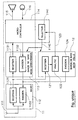
- the terminal radio telephony includes a conventional chain 11, and an additional module 12 and new, dedicated to standby mode.
- this microcontroller 114 remains permanently in activity, whether in standby or operational mode. He notably pilots activation or deactivation of the processing means 113.
- the microcontroller 114 can be completely disabled in standby mode. Indeed, the new module 12 alone provides all of the necessary functions.
- this new module 12 in standby mode is designed to consume less energy than the microcontroller 114. This is possible in particular because this module 12 only ensures, specifically, a reduced number of operations strictly necessary for standby mode.
- the modules 113 and 114 are deactivated.
- the signals received and brought back into baseband by the means 1121 supply the means 121 of reception of the standby module 12.
- These reception means 121 provide functions similar to those of module 1131.
- a simple ASIC or DSP is added, consuming less than the microcontroller 114, to fulfill the functions of module 12 dedicated to standby mode.
- memory deinterlacer buffer must have a depth of 8 frames when it comes to speech, while a depth of 4 frames is sufficient for the data of signage.
- the memory allocated to the means 121 can therefore be reduced.
- the reception means 121 therefore notably comprise means for channel decoding, deinterlacing, source decoding, ... specifically dedicated to signaling data.
- the signaling data is not intended for the terminal, and we remain in standby mode.
- the analysis means 122 carry out a simple operation, namely the transmission of a wake-up command 123 to the microcontroller 114.
- the microcontroller 114 integrates, in addition to its conventional functions, selection means 1141, which receive the wake-up command 123. The microcontroller then enters into function, and activates module 113 of the operational mode, via a command 1142 selection, which simultaneously deactivates the means 12 of the mode Eve.
- the terminal operates in a conventional manner. on the chain of processing 11.
- the microcontroller 114 which managed the communication generates, via its selection means 1141, a new selection command 1142, which causes the deactivation of the means 113 of the operational mode and the activation of the means 12 of the standby mode. Then, the microcontroller 114 ceases its activities, until that the standby means 12 activate it again.
- the standby module 12 possibly ensures the regular transmission 124 of signaling data necessary (for example for provide the base station with indications of presence, and possibly location). Again, because these means 124 are dedicated to the emission of predetermined data, they are very simple (compared to 1132 means) and can therefore be designed to consume little energy.
- an additional module 12 increases the autonomy of the device, in particular because it is no longer necessary to permanently supply the microcontroller 114.
- a single ASIC integrates the functions performed by module 12 dedicated to standby mode and module 113 dedicated to operational mode.
Landscapes
- Engineering & Computer Science (AREA)
- Computer Networks & Wireless Communication (AREA)
- Signal Processing (AREA)
- Mobile Radio Communication Systems (AREA)
- Telephone Function (AREA)
- Transceivers (AREA)
Abstract
Description
- un mode "veille", dans lequel l'appareil peut notamment détecter un appel extérieur ;
- un mode "opérationnel", mis en oeuvre lorsque l'appareil est utilisé, par exemple pour une communication.
- un mode opérationnel mis en oeuvre dans une chaíne principale, assurant les fonctions principales dudit appareil électronique ;
- un mode veille, dans lequel ledit appareil électronique est en attente d'un événement impliquant le passage au mode opérationnel.
- desdits moyens de veille et correspondant auxdits événements exceptionnels destinés auxdits moyens de la chaíne principale, de façon à activer lesdits moyens de la chaíne principale ;
- desdits moyens principaux de la chaíne principale et correspondant auxdits événements exceptionnels destinés auxdits moyens de veille, de façon à activer lesdits moyens de veille.
- l'émission de signaux ;
- la réception de signaux ;
- le codage canal ;
- le codage parole;
- le décodage canal ;
- le décodage parole ;
- la modulation ;
- la démodulation.
- la réception de signaux ;
- l'analyse des messages de signalisation reçus ;
- la démodulation ;
- l'émission de signaux correspondant aux événements exceptionnels destinés à réveiller les moyens de sélection, afin d'activer les moyens du mode opérationnel ;
- l'émission de données de signalisation à la station de base ;
- le traitement automatique de certaines opérations ;
- le décodage canal.
- au moins une antenne 111 d'émission et/ou de réception de signaux hertziens;
- un module radio 112, comprenant les moyens 1121 nécessaires au traitement radio des signaux reçus par l'antenne 111 (classiquement amplification, filtrage, transfert en bande de base, conversion analogique/numérique,...) et les moyens 1122 nécessaires à l'émission de signaux via l'antenne 111 (classiquement, de même, conversion numérique/analogique, transfert dans la bande des radio-fréquences. filtrage, amplification,...);
- un module 113 assurant le traitement des communications en bande de base, en réception 1131 (décodage canal, désentrelacement, décodage source,...) et en émission 1132 (codage source, entrelacement, codage canal,...) ;
- un micro-contrôleur 114 gérant l'ensemble des opérations, en mode opérationnel. et assurant notamment l'alimentation en signal de parole d'au moins un haut-parleur 115, et le recueil de signaux de parole à transmettre, via au moins un micro-phone 116.
Claims (8)
- Appareil électronique, notamment appareil de radiocommunication, du type susceptible de basculer entre au moins deux modes de fonctionnement :appareil électronique caractérisé en ce qu'il comprend des moyens de veille (12) à faible consommation électrique, activés à la place de moyens principaux (113.114) correspondants dans ladite chaíne principale (11) lorsque ledit appareil est en mode veille, assurant la détection d'événements exceptionnels parmi les signaux reçus par ledit appareil. de façon à activer ladite chaíne principale (11) dudit appareil électronique.un mode opérationnel mis en oeuvre dans une chaíne principale (11). assurant les fonctions principales dudit appareil électronique ;un mode veille, dans lequel ledit appareil électronique est en attente d'un événement impliquant le passage au mode opérationnel,
- Appareil selon la revendication 1, caractérisé en ce que lesdits moyens de veille (12) comprennent des moyens d'analyse (122) périodique des messages de signalisation reçus par ledit appareil.
- Appareil selon la revendication 1, caractérisé en ce qu'il comprend des moyens de sélection (1141) desdits moyens principaux (113) de la chaíne principale et desdits moyens de veille (12), en fonction notamment d'une information de réveil délivrée par lesdits moyens de veille (12).
- Appareil selon la revendication 3, caractérisé en ce que lesdits moyens de sélection (1141) font partie d'un module intelligent (114) assurant entre autres la gestion de fonctions propres audit mode opérationnel.
- Appareil selon l'une quelconque des revendications 3 et 4, caractérisé en ce que ledit module intelligent (114) comprend des moyens destinés à analyser des messages de signalisation provenant :desdits moyens de veille (12) et correspondant auxdits événements exceptionnels destinés auxdits moyens principaux (113,114) de la chaíne principale (11), de façon à activer lesdits moyens (113,114) de la chaíne principale (11) ;desdits moyens principaux (113.114) de la chaíne principale (11) et correspondant auxdits événements exceptionnels destinés auxdits moyens de veille (12), de façon à activer lesdits moyens de veille (12).
- Appareil selon l'une quelconque des revendications 1 à 5. caractérisé en ce que lesdits moyens de veille (12) comprennent un composant spécifique à faible consommation électrique.
- Appareil selon l'une quelconque des revendications 1 à 6, caractérisé en ce que lesdits moyens principaux (113,114) de la chaíne principale (11) assure au moins une des fonctions appartenant au groupe comprenant :l'émission de signaux ;la réception de signaux ;le codage canal ;le codage parole;le décodage canal ;le décodage parole ;la modulation ;la démodulation.
- Appareil selon l'une quelconque des revendications 1 à 7, caractérisé en ce que lesdits moyens de veille (12) assure au moins une des fonctions appartenant au groupe comprenant :la réception de signaux ;l'analyse des messages de signalisation reçus ;la démodulation ;l'émission de signaux correspondant aux événements exceptionnels destinés à réveiller les moyens de sélection (1141), afin d'activer les moyens du mode opérationnel (113,114) ;l'émission de données de signalisation à la station de base ;le traitement automatique de certaines opérations ;le décodage canal .
Applications Claiming Priority (2)
| Application Number | Priority Date | Filing Date | Title |
|---|---|---|---|
| FR9708943A FR2766319B1 (fr) | 1997-07-15 | 1997-07-15 | Appareil electronique, en particulier appareil de radiocommunication, du type susceptible de basculer entre au moins deux modes de fonctionnement |
| FR9708943 | 1997-07-15 |
Publications (2)
| Publication Number | Publication Date |
|---|---|
| EP0895434A1 true EP0895434A1 (fr) | 1999-02-03 |
| EP0895434B1 EP0895434B1 (fr) | 2007-02-28 |
Family
ID=9509217
Family Applications (1)
| Application Number | Title | Priority Date | Filing Date |
|---|---|---|---|
| EP98401749A Expired - Lifetime EP0895434B1 (fr) | 1997-07-15 | 1998-07-09 | Appareil électronique, en particulier appareil de radiocommunication, du type susceptible de basculer entre au moins deux modes de fonctionnement |
Country Status (4)
| Country | Link |
|---|---|
| EP (1) | EP0895434B1 (fr) |
| DE (1) | DE69837177T2 (fr) |
| ES (1) | ES2281123T3 (fr) |
| FR (1) | FR2766319B1 (fr) |
Families Citing this family (1)
| Publication number | Priority date | Publication date | Assignee | Title |
|---|---|---|---|---|
| EP2015550A1 (fr) * | 2007-07-11 | 2009-01-14 | Swissvoice SA | Procédé pour un système de communication sans fil et système de communication |
Citations (3)
| Publication number | Priority date | Publication date | Assignee | Title |
|---|---|---|---|---|
| EP0315260A2 (fr) * | 1987-11-02 | 1989-05-10 | Koninklijke Philips Electronics N.V. | Appareil téléphoniqiue cellulaire |
| EP0343528A2 (fr) * | 1988-05-21 | 1989-11-29 | Fujitsu Limited | Terminal téléphonique mobile |
| EP0655872A2 (fr) * | 1993-11-26 | 1995-05-31 | Nokia Mobile Phones Ltd. | Traitement d'un message d'appel radio |
-
1997
- 1997-07-15 FR FR9708943A patent/FR2766319B1/fr not_active Expired - Fee Related
-
1998
- 1998-07-09 DE DE69837177T patent/DE69837177T2/de not_active Expired - Lifetime
- 1998-07-09 EP EP98401749A patent/EP0895434B1/fr not_active Expired - Lifetime
- 1998-07-09 ES ES98401749T patent/ES2281123T3/es not_active Expired - Lifetime
Patent Citations (3)
| Publication number | Priority date | Publication date | Assignee | Title |
|---|---|---|---|---|
| EP0315260A2 (fr) * | 1987-11-02 | 1989-05-10 | Koninklijke Philips Electronics N.V. | Appareil téléphoniqiue cellulaire |
| EP0343528A2 (fr) * | 1988-05-21 | 1989-11-29 | Fujitsu Limited | Terminal téléphonique mobile |
| EP0655872A2 (fr) * | 1993-11-26 | 1995-05-31 | Nokia Mobile Phones Ltd. | Traitement d'un message d'appel radio |
Also Published As
| Publication number | Publication date |
|---|---|
| FR2766319A1 (fr) | 1999-01-22 |
| EP0895434B1 (fr) | 2007-02-28 |
| FR2766319B1 (fr) | 2000-08-04 |
| DE69837177T2 (de) | 2007-11-08 |
| DE69837177D1 (de) | 2007-04-12 |
| ES2281123T3 (es) | 2007-09-16 |
Similar Documents
| Publication | Publication Date | Title |
|---|---|---|
| EP2172877B1 (fr) | Dispositif électronique et gestion de communication sans fils contribuant à un tel dispositif et un équipement hôte | |
| EP0709254B1 (fr) | Système de communication d'informations par courants porteurs, notamment pour un véhicule automobile | |
| FR2702111A1 (fr) | Procédé de gestion des erreurs de transmission entre une station de base et un transcodeur dans un système de radiocommunication numérique, station de base et transcodeur correspondants. | |
| FR2953966A1 (fr) | Systeme d'etiquette de rayonnage electronique ayant une fonction de reveil basee sur une detection de champ magnetique | |
| EP0895434B1 (fr) | Appareil électronique, en particulier appareil de radiocommunication, du type susceptible de basculer entre au moins deux modes de fonctionnement | |
| WO2009010470A1 (fr) | Procede de detection du brouillage d'un reseau de radiocommunication, produit programme d'ordinateur, moyen de stockage et circuit correspondants | |
| FR2847399A1 (fr) | Recepteur a configuration double | |
| EP1074441A1 (fr) | Procédé de commande à distance d'un processus | |
| WO2004100389A2 (fr) | Dispositif de radiocommunication mettant en oeuvre au moins deux antennes, respectivement pour les radiocommunications et la radiolocalisation et systeme correspondant | |
| EP1517502B1 (fr) | Dispositif pour la ré-acquisition d'un signal modulé en cas d'interruption de la réception | |
| EP0486366B1 (fr) | Circuit d'augmentation du débit d'informations dans un système d'échange de données | |
| FR2858071A1 (fr) | Convertisseur de tension interne, dispositif semiconducteur comportant un tel convertisseur, procede de conversion d'une tension interne et procede d'attaque d'un dispositif semiconducteur | |
| EP1211818B1 (fr) | Procédé d'economie de puissance dans un systeme de radiocommunications | |
| FR3102624A1 (fr) | Procédé de validation d’une transaction lors d’une communication radio | |
| EP0863617B1 (fr) | "Système de transmission comportant au moins une station satellite munie de circuits alimentés à partir d'une source d'énergie et station satellite convenant à un tel système". | |
| WO1994014290A1 (fr) | Procede de traitement d'informations au sein d'un recepteur, en particulier de radio-messagerie, et recepteur correspondant | |
| CA3177395C (fr) | Gestion de l'alimentation electrique par cable ethernet | |
| FR2905500A1 (fr) | Telebadge a module de reveil. | |
| FR2820931A1 (fr) | Terminal de radiotransmission a inhibition des moyens de transmission radio | |
| EP4380248A1 (fr) | Procédés de changement de mode de fonctionnement d'un dispositif de communication sans fil et dispositifs associés | |
| EP3314788B1 (fr) | Module radio, dispositif et programme correspondant | |
| EP4685720A1 (fr) | Procede et dispositif de communication en champ proche | |
| EP1679807B1 (fr) | Terminal communicant et dispositif d'annulation d'au moins un signal électromagnétique sur un récepteur | |
| CA2990770C (fr) | Module radio, dispositif et programme correspondant | |
| FR2817120A1 (fr) | Terminal avec dispositif anti-nuisibles |
Legal Events
| Date | Code | Title | Description |
|---|---|---|---|
| PUAI | Public reference made under article 153(3) epc to a published international application that has entered the european phase |
Free format text: ORIGINAL CODE: 0009012 |
|
| AK | Designated contracting states |
Kind code of ref document: A1 Designated state(s): DE ES GB IT SE |
|
| AX | Request for extension of the european patent |
Free format text: AL;LT;LV;MK;RO;SI |
|
| RAP3 | Party data changed (applicant data changed or rights of an application transferred) |
Owner name: ALCATEL |
|
| RAP3 | Party data changed (applicant data changed or rights of an application transferred) |
Owner name: ALCATEL |
|
| 17P | Request for examination filed |
Effective date: 19990803 |
|
| AKX | Designation fees paid |
Free format text: DE ES GB IT SE |
|
| GRAP | Despatch of communication of intention to grant a patent |
Free format text: ORIGINAL CODE: EPIDOSNIGR1 |
|
| GRAS | Grant fee paid |
Free format text: ORIGINAL CODE: EPIDOSNIGR3 |
|
| GRAA | (expected) grant |
Free format text: ORIGINAL CODE: 0009210 |
|
| AK | Designated contracting states |
Kind code of ref document: B1 Designated state(s): DE ES GB IT SE |
|
| REG | Reference to a national code |
Ref country code: GB Ref legal event code: FG4D Free format text: NOT ENGLISH |
|
| REF | Corresponds to: |
Ref document number: 69837177 Country of ref document: DE Date of ref document: 20070412 Kind code of ref document: P |
|
| RAP2 | Party data changed (patent owner data changed or rights of a patent transferred) |
Owner name: ALCATEL LUCENT |
|
| GBT | Gb: translation of ep patent filed (gb section 77(6)(a)/1977) |
Effective date: 20070412 |
|
| PG25 | Lapsed in a contracting state [announced via postgrant information from national office to epo] |
Ref country code: SE Free format text: LAPSE BECAUSE OF FAILURE TO SUBMIT A TRANSLATION OF THE DESCRIPTION OR TO PAY THE FEE WITHIN THE PRESCRIBED TIME-LIMIT Effective date: 20070531 |
|
| REG | Reference to a national code |
Ref country code: ES Ref legal event code: FG2A Ref document number: 2281123 Country of ref document: ES Kind code of ref document: T3 |
|
| PLBE | No opposition filed within time limit |
Free format text: ORIGINAL CODE: 0009261 |
|
| STAA | Information on the status of an ep patent application or granted ep patent |
Free format text: STATUS: NO OPPOSITION FILED WITHIN TIME LIMIT |
|
| 26N | No opposition filed |
Effective date: 20071129 |
|
| PGFP | Annual fee paid to national office [announced via postgrant information from national office to epo] |
Ref country code: DE Payment date: 20170724 Year of fee payment: 20 Ref country code: GB Payment date: 20170719 Year of fee payment: 20 Ref country code: IT Payment date: 20170728 Year of fee payment: 20 Ref country code: ES Payment date: 20170825 Year of fee payment: 20 |
|
| REG | Reference to a national code |
Ref country code: DE Ref legal event code: R071 Ref document number: 69837177 Country of ref document: DE |
|
| REG | Reference to a national code |
Ref country code: GB Ref legal event code: PE20 Expiry date: 20180708 |
|
| PG25 | Lapsed in a contracting state [announced via postgrant information from national office to epo] |
Ref country code: GB Free format text: LAPSE BECAUSE OF EXPIRATION OF PROTECTION Effective date: 20180708 |
|
| REG | Reference to a national code |
Ref country code: ES Ref legal event code: FD2A Effective date: 20201002 |
|
| PG25 | Lapsed in a contracting state [announced via postgrant information from national office to epo] |
Ref country code: ES Free format text: LAPSE BECAUSE OF EXPIRATION OF PROTECTION Effective date: 20180710 |